Metal galling is a severe form of adhesive wear that occurs when two sliding metal surfaces cold-weld together under high contact pressure. As movement continues, the bonded areas tear, causing material transfer, surface scoring, and often the permanent seizure of mating parts.
If you spend any time on the shop floor, you have likely experienced this firsthand. Imagine tightening a 304 stainless steel bolt on an inspection panel. Before the bolt even reaches its target clamping force, the rotational resistance suddenly spikes. When you try to back the fastener out with a wrench, it locks up completely. Once cut open, you find the threads torn on one side and fused with transferred metal on the other.
Once galling occurs, the damage is irreversible and usually results in scrapped parts, destroyed tooling, or costly machine downtime. This guide breaks down how to quickly identify adhesive wear, the material combinations most at risk, and the exact dimensional and lubrication fixes you need to specify on your manufacturing drawings to stop it from happening.
How to Identify Galling on a Part?
Spotting the exact wear type early prevents catastrophic assembly failure. Here is how to isolate metal galling from everyday surface damage.
Material Transfer and Torn Surfaces
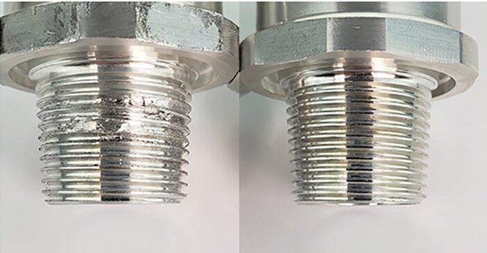
Galling is characterized by visible material transfer, raised lumps, and torn surfaces along the direction of sliding. It does not look like a clean scratch; it looks like the metal has been chewed or cold-welded. You can often feel a rough, raised edge when running your fingernail across the damage.
In sheet metal stamping, galling often presents as repeating defects on consecutive parts. If multiple stamped parts show scoring in the exact same location, operators should inspect the corresponding die radius. You will typically find sheet metal adhered directly to the tool steel in that specific area.
Cross-Threading and Abrasive Scratches
Differentiating galling from other types of surface damage dictates your corrective action. Use the physical symptoms and the timing of the failure to isolate the root cause.
| Failure Mode | When It Appears | Where the Damage is Located | Next Troubleshooting Step |
|---|---|---|---|
| Galling | Sudden spike in friction during tightening or sliding. | Raised lumps, torn metal, and material transfer on contact faces. | Review material hardness differential and check lubrication. |
| Cross-Threading | Immediate resistance at initial thread engagement. | Damaged thread crests at the leading edge of the fastener. | Check assembly alignment, starting torque, and thread pitch match. |
| Abrasive Wear | Gradual increase in wear over continuous operation cycles. | Linear grooves or plowing marks across the sliding path. | Inspect for particulate contamination and evaluate surface hardness. |
Damaged Parts and Rework
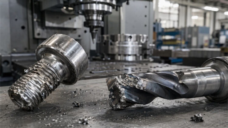
Once galling occurs, the damage is usually permanent. If a fastener seizes, forcing it out will strip the internal threads or pull out the threaded insert entirely. Both the fastener and the mating component must typically be scrapped or require thread repair inserts.
For stamping operations, identifying galling requires strict quarantine procedures. Once adhesive wear is confirmed on the die, quality control must trace the batch back to the last known good part. The die itself will likely require localized polishing or recoating before it can be returned to service, making prevention critical for minimizing downtime costs.
What Makes a Metal Contact More Likely to Gall?
Preventing adhesive wear starts with understanding the physics of your material contact. Explore the hidden variables that cause specific metal combinations to fail.
Contact Pressure and Surface Films
Galling starts at the microscopic level. Even machined surfaces have microscopic peaks and valleys known as asperities. When two surfaces are pressed together, these asperities bear the entire load.
Under sliding motion and high contact pressure, the protective oxide film breaks down, exposing bare, highly reactive metal. The resulting friction generates intense localized heat, causing the asperities to cold-weld together. As the parts continue to move, these microscopic welds tear apart, pulling base material with them.
Surface finish plays a critical role, but smoother is not always better. While rough surfaces with heavy machining marks increase friction, highly polished surfaces (below 0.25 microns Ra) can actually increase the risk of galling. Ultra-smooth surfaces increase the actual contact area and lack the microscopic valleys necessary to retain lubricants, creating a vacuum-like adhesion effect between the metals.
Material Pairing and Hardness
Self-mated materials present the highest risk. A standard engineering rule of thumb is to maintain a hardness differential of at least 50 Brinell (HB) between mating metal surfaces to prevent galling.
Austenitic stainless steels are highly susceptible due to their ductility and reliance on a thin oxide layer. In ASTM G98 threshold testing published by ASSDA, pairing a 304 stainless steel component against another 304 component, or pairing 304 against annealed 316, yields identical poor results. Both pairings gall at a threshold stress of just 13 MPa. When designing or sourcing replacement parts, always review material grade, hardness, and surface condition as a complete system.
Aluminum and titanium also exhibit high galling tendencies—titanium is notorious for adhesive wear during aerospace forming operations, while aluminum frequently galls in untreated precision sliding fits due to its softness.
How to Prevent Galling in Threads, Sliding Parts, and Dies?
Stopping galling requires more than just adding random lubricants to the assembly. Discover the proven design and tooling adjustments that protect your most vulnerable components.
Threaded Fasteners
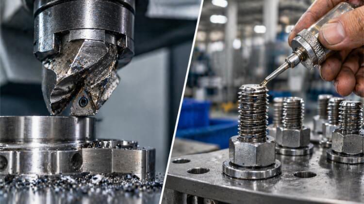
Troubleshooting should follow the actual shop floor sequence: verify thread cleanliness, remove machining burrs, ensure proper starting alignment, and check the thread pitch. Coarse threads generally gall less than fine threads. Next, evaluate your tightening speed and lubrication state.
For an assembly like an inspection panel that requires repeated removal, evaluate three options: applying anti-seize paste manually, sourcing pre-coated fasteners, or swapping one mating part (e.g., using a Nitronic 60 nut with a 304 bolt).
When you introduce a new lubricant or thread coating, you must re-verify the tightening conditions with the actual fastener combination. Lubricants drastically reduce friction, meaning your standard “dry” torque value will generate a much higher clamping force. If you do not reduce the torque spec for a “wet” installation, you will stretch or snap the bolt.
Pro Tip: Ban impact wrenches on stainless hardware. High-speed rotation generates instant frictional heat that guarantees galling before the nut even seats. Always use hand tools or slow-speed, torque-controlled drivers.
Sliding Parts
When addressing a galled shaft and bushing, start with the physical setup: check running clearance, shaft alignment, edge loading, and lubrication retention.
Engineers evaluate sliding contacts using the PV limit (Pressure × Velocity). This metric represents the frictional heat generated; if the heat exceeds the material’s thermal dissipation limit, the asperities will melt and weld together.
PV = Nominal Contact Pressure × Sliding Speed For example: 2 MPa × 0.10 m/s = 0.20 MPa·m/s. You must check this calculated result against the bushing manufacturer’s datasheet, alongside the maximum allowable pressure, speed, and operating temperatures for that specific material.
If your solution involves adding a flanged bushing, applying a dry-film lubricant, or specifying hardcoat anodizing for aluminum components, always factor the coating thickness into the actual fit. Verify the final assembly using post-treatment dimensions.
Stamping Dies
Once you confirm the exact location of material transfer on the die, check lubrication coverage, inspect the die entry radius, and evaluate the surface condition of the contact area.
When comparing process adjustments versus applying tool coatings like DLC (Diamond-Like Carbon), record exactly what was modified for each iteration. Verify the effectiveness of the fix during a continuous stamping trial (e.g., checking the tool after a 500-stroke warm-up run) to ensure material does not gradually build up again over a long production run.
What to Put on the Drawing, RFQ, and Work Instructions?
A gall-free assembly begins long before the parts hit the shop floor. Learn exactly how to specify tolerances, coatings, and assembly steps in your documentation.
Drawing and Bill of Materials
Vague notes lead to assembly failures. For the inspection panel, a drawing note should explicitly define the material pairing, surface treatment, and post-coating dimensional requirements.
Example Drawing Note: *”Fasteners: 304 SS, Silver-Plated. Mating Inserts: Nitronic 60. Threads and sliding fits must meet dimensional requirements after all plating and surface treatments are applied.”*
RFQ and Supplier Substitutions
When sourcing parts, procurement must evaluate the total cost of the fix. Manual lubrication is cheap per part but adds assembly time; pre-coated fasteners cost more upfront but become more cost-effective at volume.
| Prevention Method | Part Cost | Assembly Time | Lead Time | Spares Availability | Re-qualification Effort |
|---|---|---|---|---|---|
| Manual Anti-Seize | Low | High | Standard | High (Standard parts) | Low (Verify torque limits) |
| Pre-Coated Fasteners | Medium | Low | Longer | Medium (Custom order) | Medium (Verify coating durability) |
| Material Substitution | High | Low | Longer | Low (Specialty alloys) | High (Requires full joint validation) |
Always require suppliers to explicitly state any proposed material, coating, or lubricant substitutions on their quotes so engineering can review the galling risk before issuing the purchase order.
Assembly and Tooling Instructions
Shop instructions must remove operator guesswork. Assembly documents should state the exact lubricant specification, where to apply it (e.g., *”apply to leading three threads”*), the validated tightening speed limits, and rules for reapplication during field maintenance.
For press shops, stamping routing cards must detail the lubrication method, exact locations for quality checks, and the standard operating procedure for operators to follow the moment initial material transfer is detected—which should immediately trigger a machine stop and quarantine of the current batch.
How to Verify the Fix Before Production?
You cannot afford to test a new prevention strategy during full-scale manufacturing. Use these targeted validation methods to prove your fix works before signing off.
Material Screening
Engineers use the ASTM G98 standard test method to compare the baseline galling resistance of different material pairings under controlled conditions. While this button-on-block test is excellent for screening out high-risk alloy combinations during the design phase, it is a static, clean-environment test. It cannot account for thermal expansion, particulate contamination, or the complex geometry of your actual assembly. Final part release must always be based on validation testing that replicates your real-world applied loads, lubrication state, and shop-floor operating conditions.
Production Trials
A successful fix on paper means nothing if it fails under physical stress. Validation trials should match the exact conditions the parts will experience in the field or the press room.
| Scenario | Verification Method | Acceptance Criteria |
|---|---|---|
| Inspection Panel Fasteners | Use production-intent fasteners, coatings, and assembly tools. Repeatedly assemble and disassemble based on expected maintenance cycles. | Achieves target clamp load and releases smoothly. Running torque must not increase by more than 10-15% across cycles, and threads show no visible adhesion, deformation, or tearing. |
| Shaft and Bushing | Run the assembly under actual load, speed, stroke length, and planned lubrication conditions. | Completes the specified duty cycle. Running resistance and contact surface wear remain strictly within project tolerance limits. |
| Stamping Die | Execute a continuous trial run using production-grade sheet metal and validated press parameters. Inspect the tool at set intervals. | Stamped parts meet visual and dimensional standards. Critical die radii show no progressive material buildup. Forming tonnage remains stable without unexplained spikes. |
Production Release and Requalification
Documentation closes the loop. A formal release record ensures the fix is proven and locks in the assembly standard for production.
The number of test cycles and exact limits are dictated by your product’s lifecycle requirements. Crucially, if procurement later changes the fastener supplier, plating vendor, or lubricant brand, engineering must immediately trigger a requalification test to verify the new variables do not reintroduce galling.
Example: First Article Release Record – Inspection Panel
| Test Configuration | Required Cycles | Acceptance Criteria | Result | Engineering Sign-off |
|---|---|---|---|---|
| 304 SS Bolt + Nitronic 60 Nut (Unlubricated) | 25 Install/Remove Cycles | Target preload achieved at specified torque (± 5%). Zero thread tearing or seizure. | PASS | J. Smith – 11/10/2026 |
Ready to eliminate galling in your next project?
Whether you are struggling with seized stainless fasteners on the assembly line or need DFM guidance for a complex sliding mechanism, the Shengen engineering team can help. Send us your CAD files and operational requirements, and we will run a material compatibility review to help you specify the right alloys, tolerances, and surface treatments for reliable, gall-free production.
Hey, I'm Kevin Lee

For the past 10 years, I’ve been immersed in various forms of sheet metal fabrication, sharing cool insights here from my experiences across diverse workshops.
Get in touch
Kevin Lee
I have over ten years of professional experience in sheet metal fabrication, specializing in laser cutting, bending, welding, and surface treatment techniques. As the Technical Director at Shengen, I am committed to solving complex manufacturing challenges and driving innovation and quality in each project.