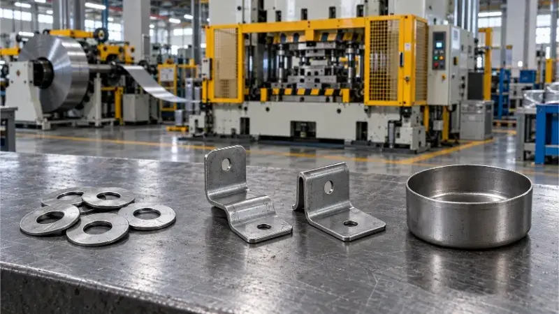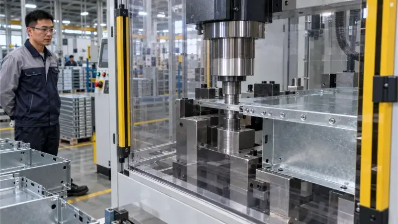

Progressive dies carry parts on a continuous metal strip for high-volume, multi-step production. Compound dies perform all cutting in a single stroke for highly precise, flat parts. Transfer dies move independent blanks between stations using mechanical fingers, making them ideal for deep-drawn or complex geometries.
Choosing the wrong stamping method doesn’t just inflate your piece price—it can lead to excessive material scrap, dimensional tolerance issues, or even catastrophic tool failure during production.
Based on decades of real-world fabrication experience on the factory floor, this guide breaks down the engineering mechanics, hidden costs, and dimensional limits of each stamping method. Use the quick selection matrix below to screen your project before investing capital into hard tooling.
Quick Selection Matrix
| Process[cite: 39] | Priority Evaluation Conditions & Typical Volume[cite: 39] | Primary Limitations[cite: 39] | Cost Considerations[cite: 39] |
|---|---|---|---|
| Progressive Die[cite: 39] | Part can remain attached to a carrier web during multi-step processing. Usually for stable demand (>50,000 parts/year).[cite: 39] | Carrier connection locations, strip layout, and forming space.[cite: 39] | High tooling investment; material waste from the carrier web vs. continuous high-speed output.[cite: 39] |
| Compound Die[cite: 39] | Multiple blanking and piercing operations can be completed in the same station and stroke.[cite: 39] | Tool wall thickness constraints, stripping mechanisms, and part ejection.[cite: 39] | Lower tooling budget; excellent for concentricity, but slower production efficiency.[cite: 39] |
| Transfer Die[cite: 39] | Multi-step forming requires independent blank handling (e.g., deep draws).[cite: 39] | Clamping, positioning, transfer space, and mechanical timing.[cite: 39] | High transfer system costs; excellent material yield offsets slower running speeds.[cite: 39] |
Note: These conditions serve as a preliminary screening tool. The final process plan requires verification against part drawings, material specifications, available press equipment, and exact volume requirements.
How Progressive, Compound, and Transfer Dies Work?
To determine which process fits a specific part, it is necessary to first understand the mechanical differences in how each method handles the material.
Progressive Dies
In a progressive die, a continuous coil of metal strip feeds through a sequence of stations. Each station performs one or more distinct operations, such as piercing, forming, bending, or coining. The defining characteristic is the carrier web—a portion of the metal strip that connects all parts and pulls them through the die. Pilot pins enter pre-punched holes in this web to ensure exact positioning (progression pitch) before each press cycle.
While a single part requires multiple strokes to travel from the first punching station to the final cutoff, the press produces one completed part (or multiple, depending on the layout) with every single stroke once the die is fully loaded. Because the feed mechanism is automated and the strip is continuous, progressive dies operate at high speeds, typically ranging from 100 to over 800 strokes per minute (SPM).
Compound Dies
A compound die performs multiple cutting operations in a single station during a single press stroke. Using a standard metal washer as an example, the die pierces the internal hole and blanks the external circular profile simultaneously as the press comes down.
Because all cutting happens at once, the finished part, the scrap plug (from the inner hole), and the remaining metal strip must be separated and ejected from the exact same location using knockouts or stripping plates. This ejection requirement typically limits the running speed compared to progressive dies.
(Note: In this guide, “compound die” refers strictly to tools that perform multiple cutting operations simultaneously. Tools that combine cutting and forming in one station are classified as combination dies.)
Transfer Dies
Transfer dies process independent metal blanks rather than a continuous strip. The blank is either separated from the coil at the first station or fed into the press as a pre-cut piece. Mechanical transfer fingers, rails, or robotic arms grip the part and move it sequentially from one independent tool station to the next.
Because the part is entirely detached from a carrier web, each station utilizes specific clamping and positioning mechanisms. This independent handling allows the transfer system to rotate or flip the part between stations if tooling access from different angles is required. Due to the physical limits of the mechanical transfer motion, these dies run at lower speeds, typically between 15 and 60 SPM.

Match Part Geometry to Process and Equipment Limits
Before comparing costs, you must determine if a part’s geometric features strictly restrict it to a specific stamping process.
Flat Profiles
For flat components like washers, shims, or plates with multiple slots, a compound die is usually evaluated first. Performing all blanking and piercing in one stroke ensures unmatched concentricity and dimensional accuracy between the internal holes and the outer edge.
However, certain conditions force flat parts into a progressive route. If holes are distributed too closely to each other or too close to the outer edge, the die steel between the cuts becomes too thin to withstand the blanking pressure. In a progressive die, these hole-punching operations can be separated across different stations to maintain tool strength. Additionally, if the total blanking perimeter requires more tonnage than a single station can handle, the load must be distributed progressively.
💡 Shengen Engineering Tip: Do not assume a compound die is always the default for flat parts. Carefully check the narrow edges on your drawing. If the distance between a hole and the part’s edge is less than 1.5 times the material thickness, a single-stroke compound die matrix may lack the structural integrity to survive high-volume runs.
Bent Features
When evaluating parts with bent features, such as brackets or electrical contacts, the primary consideration is the location of the carrier web.
In a progressive layout, the part must stay connected to the strip. You must determine if this connection point interferes with the bending sequence or if folding the metal requires space that the continuous strip blocks. If the geometry does not allow for a viable carrier web connection throughout the bending sequence without crushing the part, it cannot be manufactured progressively. It must either be stamped flat and formed in a secondary operation, or processed using a transfer die.
Drawn Shapes
Drawn parts, such as deep cups, motor housings, or thin-walled shells, rely heavily on controlled material flow. As the punch draws the metal into the cavity, the blank must be allowed to flow inward from its outer edges.
If the blank remains connected to a rigid carrier web, the web acts as an anchor. This restricts material flow, leading to excessive thinning and tearing of the metal.
💡 Rule of Thumb: If the depth of a drawn feature exceeds half of the part’s diameter, the material restriction of a continuous carrier web usually causes defects. In such cases, cutting the blank completely free and moving to a transfer die is the standard engineering requirement. The independent handling provides the clearance needed to draw the metal over multiple stations safely.
Equipment Capability Check
A feasible tool design is useless if the factory floor cannot run it. Before finalizing a route based on part geometry, verify the equipment limits:
- Press Tonnage & Energy: Does the press have sufficient force for the operations, particularly for the high concentrated loads of single-station compound blanking?
- Bed Size & Stroke Length: Multi-station progressive and transfer dies require adequately sized press beds. Transfer dies and deep-drawn parts also require a long enough press stroke to allow part extraction and mechanical finger clearance during transfer.
- Automation Limits: Can the coil feeders, straighteners, and transfer mechanisms accurately handle the specific material thickness, width, and progression pitch required?
Compare Dimensional Control and Part Quality
Before reviewing quotes and tooling budgets, you must confirm that the selected process can consistently meet the tolerances on your drawing.
Feature Location and Tolerance Stack-up
Dimensional control often dictates the tooling route, especially for relationships like hole-to-outer-edge or hole-to-bend distances.
In a compound die, the internal holes and the outer profile are cut at the exact same moment. This single-station processing naturally controls concentricity, meaning the relationship between the hole and the edge remains stable without complex tracking.
In a progressive or transfer die, the part moves across multiple stations. A hole might be pierced in station 2, while the outer edge is trimmed in station 5, and a bend occurs in station 7. Even with high-precision pilot pins or transfer grippers, micro-movements occur during positioning. This introduces tolerance stack-up. If your critical assembly features do not share the same datum reference in the die sequence, your final CMM report will likely fail. Tool designers must plan the sequence carefully to punch critical features in the same station whenever possible.
Edge Quality and Flatness
The tooling process directly affects the physical condition of the part’s edges. When a punch pushes through metal, it creates a rollover on one side and a sharp burr on the other. Because parts in a progressive die typically stay flat on the die block, the burr direction is usually uniform. In transfer dies where parts might be flipped for different operations, burr direction requires specific attention.
Furthermore, do not assume that processing a flat part in a single stroke guarantees a perfectly flat outcome. In compound dies, the ejector pads or stripping plates apply immense pressure to push the part out of the tight die cavity. On thinner materials, this stripping force can cause dishing or bowing. If your drawing mandates strict flatness or a burr-free edge, secondary operations like vibratory tumbling or roller leveling must be planned. These operations add lead time and unit cost, which must be factored into your RFQ comparisons regardless of the primary stamping method.
Forming Defects and Material Behavior
For parts requiring bending or deep drawing, the manufacturing route affects how the material behaves under stress. Common forming defects include springback, wrinkling, cracking, and surface galling.
Material thickness, temper, and lubrication dictate how severe these defects might be. A progressive die might struggle with a deep draw because the attached carrier web limits material flow, leading to tearing. Moving that same part to a transfer die allows the material to flow freely, often eliminating the cracking issue.
When evaluating First Off Tool (FOT) samples, engineers must verify more than just dimensions. Visual surface conditions, material thinning at the bend radii, and assembly fitment must be validated before full production begins.
Process Decision Checkpoint: Only compare the financial costs of different stamping routes after confirming that they can both reliably meet the same quality and acceptance criteria. A cheaper tool is a liability if it produces a 15% reject rate.
Compare Total Costs and Actual Production Output
Once technical feasibility is established, the decision shifts to project economics. The most cost-effective route depends entirely on how tooling investment balances against material yield and production volume.
Tooling Investment
Tooling cost encompasses die design, CNC machining, assembly, sensor integration, and tryout phases.
Generally, progressive dies require higher initial capital because they utilize a larger die set with multiple complex stations to handle the continuous strip. Transfer dies also carry high costs, not necessarily from the die stations themselves, but from the required automation (transfer fingers, servo drives) needed to move the independent blanks. Compound dies usually require the lowest initial investment due to their compact, single-station structure.
However, avoid fixed tooling price rankings and consider long-term maintenance. Sharpening and maintaining a 12-station progressive die is significantly more expensive and time-consuming than servicing a single-station compound die. Additionally, executing an Engineering Change Order (ECO) on a progressive die later in the project lifecycle may disrupt the entire progression pitch, leading to costly rebuilds.
Material Yield (The Hidden Cost Driver)
Material consumption is often the decisive factor between progressive and transfer die stamping, especially when processing expensive materials like copper, stainless steel, or aerospace alloys.
In progressive stamping, the carrier web and connecting bridges are mandatory to transport the part. This setup generates a fixed percentage of skeleton scrap—often 15% to 30% of the total coil weight. In transfer stamping, because the part is cut free immediately, the carrier web is eliminated.
While transfer dies still generate some scrap from the initial blanking, the material savings are significant. You must evaluate the specific strip layout for both options. Keep in mind that material yield calculations must also account for tryout loss, coil-end scrap, and setup waste, not just the theoretical layout.

Output and Payback
Do not confuse theoretical press speed (Strokes Per Minute, SPM) with Overall Equipment Effectiveness (OEE). A progressive die running at 400 SPM seems superior on paper, but actual qualified yield drops when accounting for coil changeovers, sensor fault stops, and routine maintenance downtime.
To make an objective decision, evaluate the costs based on your single-batch quantity, annual volume, and total project lifecycle.
💡 Shengen Engineering Cost Calculation Example:
To compare two viable routes, lock in the material grade, quality specs, and delivery terms, then calculate:
Total Project Cost = Initial Tooling Investment + (Total Quantity × Comprehensive Cost per Part)
Scenario: A heavy copper busbar with an estimated lifecycle volume of 200,000 pieces.
- Route A (Progressive Die):
- Tooling Cost: $40,000
- Unit Cost: $0.85 (High SPM lowers labor cost, but the carrier web wastes expensive copper).
- Route B (Transfer Die):
- Tooling Cost: $55,000 (Higher initial cost due to transfer automation).
- Unit Cost: $0.65 (Slower SPM increases labor/machine time, but eliminating the carrier web saves significant copper).
Break-even Analysis: At 75,000 parts, both routes cost 103,750. For the full 200,000-piece project, the Transfer Die saves 25,000 overall, despite the more expensive tooling and slower press speed.
Select a Route and Compare Supplier Quotes
After understanding the technical limits and cost drivers, the final step is moving your project into procurement. Evaluating tooling options requires a structured screening process and a strict method for comparing supplier proposals.
Process Screening
When determining the most viable stamping route, work through these criteria in order:
- Station limits: Can all blanking and piercing operations be completed in a single station? (Evaluate Compound Die).
- Carrier web viability: If multi-station processing is required, can the part remain attached to a continuous strip without crushing existing features or restricting material flow? (Evaluate Progressive Die).
- Independent handling: Does the part require deep drawing, flipping, or complex re-orientation that forces it to be detached from the coil? (Evaluate Transfer Die).
- Quality verification: Can the selected route and available press equipment reliably meet the dimensional tolerances and edge quality requirements?
- Economic fit: Based on the expected lifecycle volume, which route offers the best balance of initial tooling amortization and material yield?
Important Note: If your part design is still fluid or market demand is unproven, do not commit to hard mass-production tooling immediately. Evaluate alternative manufacturing routes—such as laser cutting, turret punching, or soft prototype tooling—to validate the design before investing heavy capital into progressive or transfer dies.
Quote Comparison
A common procurement mistake is looking exclusively at the bottom-line piece price and tooling cost. Before comparing numbers, you must align the scope of the quotes to ensure you are comparing identical parameters:
- Material assumptions: Check the specified grade, temper, and thickness. Crucially, compare the assumed strip layouts. Did one supplier quote a wider progression pitch, resulting in higher hidden material waste?
- Quality and acceptance: Ensure all quotes reflect the same dimensional tolerances and visual inspection criteria.
- Secondary operations: Is deburring, vibratory tumbling, or roller leveling included in the piece price, or listed as a separate surcharge?
- Volume and capacity: Are the quotes based on the same minimum batch size (MOQ) and Annual Estimated Usage (EAU)?
- Tooling ownership and maintenance: Clarify what the tooling fee covers. Who owns the die after it is paid for? Crucially: Is routine sharpening and maintenance absorbed into the piece price (amortized), or will you receive surprise invoices for die maintenance after 50,000 hits?
RFQ Checklist
To receive an accurate and actionable quote rather than a rough estimate, provide your stamping partner with a complete data package:
- Engineering files: 2D PDF drawings (with full tolerances) and 3D CAD models (STEP/IGES), clearly marked with the current revision level.
- Material specifications: Exact material grade, temper, thickness, and any specific grain direction requirements for critical bends.
- Feature controls: Clear identification of critical-to-function dimensions, required burr direction, and designated cosmetic surfaces.
- Volume projections: First article inspection (FAI) quantity, standard production batch size, and expected annual volume.
- Fulfillment requirements: Surface treatments (plating, coating), required quality documentation (e.g., PPAP, material certificates), and packaging specifications.
As a custom metal fabrication facility based in Dongguan, China, Shengen combines robust tooling capabilities with an extensive local supply chain for raw materials and surface treatments. We review your prints to determine the most stable manufacturing route, calculate realistic strip layouts to optimize material yield, and identify critical forming risks before cutting steel.
Whether you need a bridge-tooling solution for market validation or a high-volume stamping program, our engineering team ensures the process aligns with your budget and quality requirements. We do not promise that soft prototype tools can magically upgrade into high-speed progressive dies—we build the right tool for the right phase of your project. Submit your drawings and volume requirements to Shengen for a comprehensive DFM review and tooling assessment.
Hey, I'm Kevin Lee

For the past 10 years, I’ve been immersed in various forms of sheet metal fabrication, sharing cool insights here from my experiences across diverse workshops.
Get in touch
Kevin Lee
I have over ten years of professional experience in sheet metal fabrication, specializing in laser cutting, bending, welding, and surface treatment techniques. As the Technical Director at Shengen, I am committed to solving complex manufacturing challenges and driving innovation and quality in each project.