Thread milling is a CNC machining process that creates internal or external threads using a rotating cutter moving in a helical path. Unlike traditional tapping, it uses lower cutting forces, making it the safest method for threading hard metals, blind holes, and high-value components.
Every machinist knows the sinking feeling of snapping a standard tap inside a nearly finished, expensive part. When process security becomes more critical than raw speed, thread milling is the engineering answer. It requires precise CNC interpolation and careful tool selection, but it grants complete control over pitch diameters and chip evacuation.
This guide breaks down exactly how the cutting motion works, the financial crossover point between milling and tapping, and the shop-floor strategies used to hold strict thread tolerances without scrapping parts.
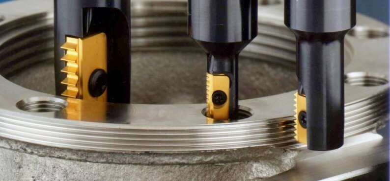
How CNC Thread Milling Creates a Thread?
This section outlines the mechanics of the process before factoring in tooling costs or manufacturing strategy.
Helical Interpolation
Thread milling relies on three synchronized machine movements, known as helical interpolation. The CNC controller coordinates these axes simultaneously:
- The cutting tool rotates on its own central axis.
- The center of the tool moves in a circular path along the X and Y axes.
- The machine spindle moves along the Z-axis exactly one thread pitch per full circle.
The combination of the circular X-Y motion and the linear Z-axis motion generates the thread form. Unlike tapping, the tool’s rotational speed does not dictate the thread pitch; the CNC interpolation controls it.
Example: For an M10 × 1.5 thread, the toolpath moves exactly 1.5 mm along the Z-axis during one complete circular revolution.
Cutting Load and Radial Engagement
The cutting load in thread milling is drastically lower than in tapping.
A tap engages 100% of the hole’s circumference simultaneously, requiring massive torque and generating significant cutting forces. A thread mill typically engages only 10% to 15% of the bore at any given moment.
Because radial engagement is limited, machinists can divide the total thread depth into multiple lighter passes. This lowers the cutting torque, reduces the risk of deformation on thin-walled parts, and allows for manageable cutting loads when machining tough alloys like titanium.
Entry, Cutting, and Exit
A standard thread milling operation follows a strict sequence to ensure thread quality and preserve tool life:
- Drill or bore the pilot hole to the specified minor diameter.
- Chamfer the hole opening to remove burrs.
- Position the thread mill safely inside the hole.
- Arc-in to the hole wall.
- Execute the helical toolpath.
- Run an additional spring pass (finishing pass) if required by the tolerance.
- Arc-out and retract the tool clear of the part.
The arc-in motion is a critical step. Engaging the material through a gradual curve rather than a straight line reduces sudden radial shock on the cutter. Without this arcing motion, the tool is prone to deflection, which causes tapered threads (where the top of the hole is wider than the bottom) and leaves a visible witness mark on the thread crest.
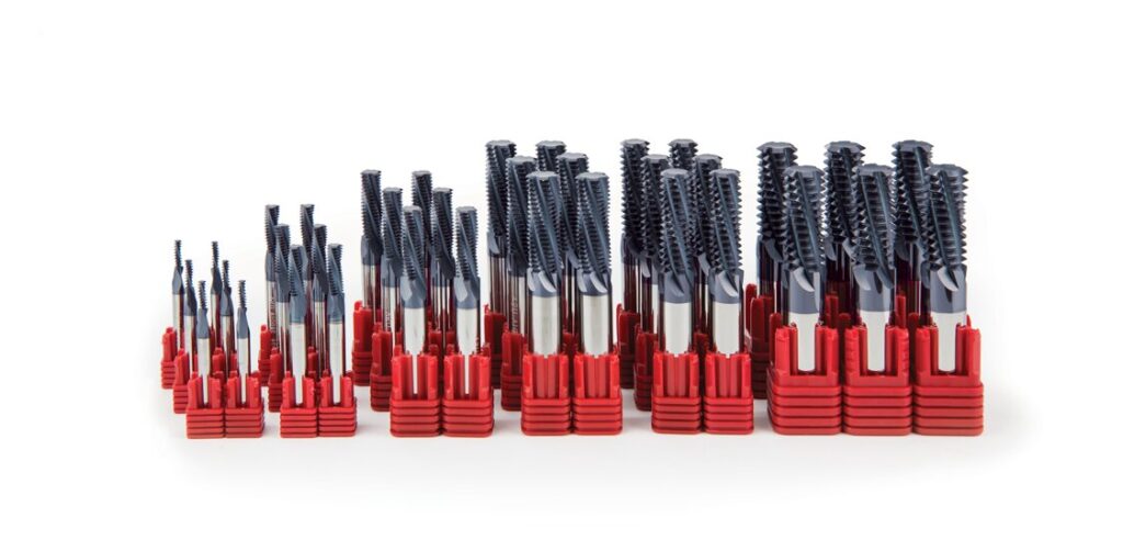
Thread Milling vs. Tapping: Where Each Works Best
Process selection depends on part geometry, material properties, and mitigating production risk.
High-Value and Difficult Parts
In heavy machining environments, thread milling is the default method for:
- Stainless steel, titanium, and Inconel.
- Hardened steels and other difficult-to-machine materials.
- Large-diameter threads.
- Deep blind holes where chip packing is a hazard.
- Thin-walled components.
- Projects requiring precise adjustments to the pitch diameter.
The engineering reasoning is purely practical. Dispersing the cutting load over multiple passes manages heat and prevents tool failure. If a thread mill does break, its diameter is smaller than the hole, meaning it simply falls out or can be easily blown out with air.
Conversely, a broken tap often requires EDM extraction—which adds days to the lead time, or forces the shop to scrap a 500 manifold just because a 20 tap snapped in the final operation. Furthermore, CNC cutter compensation allows the machinist to dial in the thread size precisely using a Go/No-Go gauge, a level of control tapping cannot offer.
The Tapping Sweet Spot
Tapping remains highly effective and is usually the better choice for:
- Small-diameter standard threads.
- Aluminum, brass, and easy-to-machine mild steel.
- High-volume production runs of identical holes.
- Standard assembly joints where fine pitch diameter adjustments are unnecessary.
- Older equipment that lacks stable helical interpolation capabilities.
The baseline rule: Thread milling offers control and flexibility. Tapping offers speed and simplicity.
Total Cost and RFQ Requirements
Comparing the upfront price of a tap versus a thread mill only accounts for a fraction of the actual expense. Buyers and production engineers should evaluate the cost per threaded hole.
Total production cost includes programming time, initial setup, cycle time per hole, and expected tool life. It also requires factoring in the frequency of tool changeovers, the cost of handling a broken tool, scrap risk, tool inventory consolidation, and inspection time.
We often see RFQs that only specify the thread size. To get an accurate quote and avoid production delays, ensure your documentation is complete.
What to Include in a Thread Milling RFQ:
- Thread standard and size (e.g., M8x1.25, 1/4-20 UNC)
- Internal or external thread
- Right-hand or left-hand thread
- Through hole or blind hole
- Full thread depth
- Tolerance class (e.g., 6H, 2B)
- Material and hardness
- Order quantity
- Specific inspection requirements
Choose the Right Thread Mill
Selecting the correct thread mill is an engineering decision—not just a matter of browsing a tool catalog. It requires matching the tool’s physical geometry and carbide substrate to the specific project conditions.
Single-Form vs. Multi-Form Cutters
| Cutter Type | Best Suited To | Main Advantage | Main Limitation |
|---|---|---|---|
| Single-form | Custom threads, deep holes, and small batches | Greater flexibility | Longer cycle time |
| Multi-form | Standard threads and repeat production | Faster machining | Usually pitch-specific |
When evaluating the tool profile, engineers must balance cycle time against tooling flexibility:
- Single-form cutters have a single cutting profile. They can machine multiple thread diameters—provided the pitch is the same—and are largely unrestricted by thread depth. However, because they cut only one thread pitch per revolution, they require multiple helical passes to complete a deep hole, resulting in a longer cycle time.
- Multi-form cutters feature multiple teeth spaced exactly one pitch apart along the cutting edge. They cut the entire thread depth in a single 360-degree helical pass, drastically reducing cycle time. The trade-off is reduced versatility: a multi-form tool is locked to a specific pitch, and its effective flute length must be equal to or slightly greater than the required thread depth.
- Deep hole considerations: For deep holes, machinists must verify the neck clearance of the tool. Heavy radial cutting forces can cause tool deflection. In deep applications, a single-form tool or a staggered-tooth cutter is often a safer choice to manage cutting pressure.
Solid Carbide vs. Indexable Tools
The choice between solid and indexable tooling generally comes down to the thread diameter, precision requirements, and machine rigidity:
- Solid carbide tools are the standard for small to medium diameters and high-precision threads. They offer superior rigidity. However, small-diameter solid carbide tools are highly sensitive to spindle runout (TIR); even 0.01 mm of runout can cause uneven wear or snap a micro-thread mill instantly. Long-reach solid carbide tools are typically required for deep cavities.
- Indexable tools use replaceable carbide inserts mounted to a steel body. They are typically the most cost-effective choice for large threads over M24 (or 1 inch) and heavy roughing cuts. While the upfront cost of the tool body is high, the cost per cutting edge is much lower.
- Machine requirements: Large indexable thread mills require significant machine rigidity and spindle torque. If the setup lacks rigidity, chatter will destroy the thread finish and shatter the insert. Ultimately, insert price alone cannot replace a comprehensive cost-per-hole calculation.
Material, Thread, and Hole Conditions
Before selecting a tool and calculating feeds and speeds, machinists review a standard checklist of project conditions:
- Workpiece material and hardness
- Thread diameter, pitch, and thread form
- Tolerance class (e.g., 6H, 2B)
- Internal vs. external thread
- Through hole vs. blind hole
- Full thread depth and maximum tool overhang
- Production volume
- Machine RPM limits and overall rigidity
Shop-Floor Material Tips:
- Aluminum: Focus on preventing built-up edge (BUE) and managing chip evacuation.
- Stainless Steel: Focus on preventing work hardening. The tool must keep feeding; dwelling or rubbing against the wall will instantly harden the material and destroy the cutter.
- Titanium: Focus on heat management. Titanium does not dissipate heat well, meaning the heat transfers directly into the cutting edge.
- Hardened Steel: Focus on managing abrasive tool wear through proper coating selection and controlled cutting speeds.
- Deep Blind Holes: Focus on neck clearance and preventing chip packing at the bottom of the bore.
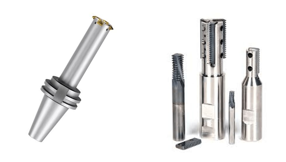
Program a Stable Thread Milling Cycle
Programming a thread mill requires a solid understanding of CNC toolpaths, cutter compensation, and chip dynamics.
Reading a Helical Toolpath
Below is a simplified example of a helical toolpath using standard G-code (common on Fanuc and similar controllers).
G-Code
G00 X0. Y0. Z2.0         (Rapid move to hole center, safe Z clearance)
G01 Z-15.0 F500.         (Feed down to the bottom of the hole)
G41 D01 X5.0 Y0. F150.   (Engage Cutter Radius Compensation, arc-in to the wall)
G03 X5.0 Y0. I-5.0 J0. Z-13.5 (Helical interpolation: full circle while Z moves up one pitch)
G00 X0. Y0.              (Arc-out to center)
G40                      (Cancel Cutter Radius Compensation)
G00 Z10.0                (Rapid retract out of the hole)
Key variables to understand:
- G02 / G03: Dictates the circular direction (clockwise or counter-clockwise).
- I, J (or R): Defines the radius and center point of the circular path in the X-Y plane.
- Z: Defines the axial movement (pitch drop) per revolution.
- G41 / G42 (Cutter Radius Compensation): This is thread milling’s commercial secret weapon. If a Go/No-Go gauge check shows the thread is 0.02 mm too tight, the operator doesn’t scrap the part. They simply adjust the wear offset in the controller by 0.01 mm and re-run the toolpath to achieve a perfect fit.
The Feed Rate Trap:
The feed rate programmed in the CNC (centerline feed) is NOT the same as the actual cutting feed rate at the hole wall. For internal threads, you must reduce the programmed feed rate to prevent overloading the tool.
Formula:
Programmed Feed = Desired Feed × (Thread Dia - Cutter Dia) / Thread Dia
Note: This code is for illustration only. Actual commands, offsets, directions, and safety moves depend strictly on the CNC controller, cutter, and thread configuration.
Climb Milling and Toolpath Direction
Toolpath direction is not a universal constant. It changes based on whether the thread is internal or external, and whether it is right-hand or left-hand.
In our machine shops, the standard approach for a typical internal right-hand thread is to use bottom-up climb milling.
By starting at the bottom of the blind hole and interpolating upward (using G03 for a standard right-hand tool), the cutter naturally pulls the chips up and out of the hole. If programmed top-down, the tool pushes chips into the bottom of the hole, which frequently causes chip recutting, poor surface finish, and tool breakage.
Coolant and Chip Control
Coolant strategy in thread milling is dictated by the material and the hole geometry. Applying a “standard” cooling method to every project is a recipe for failure.
- Aluminum: Requires high-volume flood coolant to flush chips rapidly and prevent aluminum from welding to the cutter (BUE).
- Stainless Steel & Titanium: Heat and friction are the primary enemies. High-pressure coolant—ideally through-spindle coolant (TSC) if the cutter supports it—is highly recommended to blast heat away from the cutting zone and clear chips from deep bores.
- Hardened Steels: Liquid coolant can cause thermal shock to the carbide edge in high-hardness applications, leading to micro-fracturing. Dry machining with a compressed air blast is often the preferred method.
- Blind Holes: Relying on standard external coolant nozzles to reach the bottom of a deep blind hole is risky. If TSC is unavailable, operators must ensure the air blast or coolant pressure is properly aligned to flush the bottom of the cavity. MQL (Minimum Quantity Lubrication) can work well, but its suitability depends strictly on the material’s thermal properties and tool manufacturer recommendations.
How to Hold Thread Size and Avoid Scrap?
Once the toolpath is programmed and the cutter is loaded, the focus shifts to process control. This phase is about managing clearances, compensating for tool deflection, and verifying dimensions against the engineering drawing.
Pilot Hole and Blind-Hole Clearance
A perfect thread milling toolpath will fail if the hole preparation is flawed. The pilot hole dictates the minor diameter of an internal thread and directly impacts the cutting load.
- Undersized pilot holes force the thread mill to remove excess material, increasing radial cutting pressure, which leads to tool deflection or immediate breakage.
- Oversized pilot holes result in a truncated (flattened) thread crest and an incomplete profile, which will fail a minor diameter pin gauge check.
- Chamfering the hole opening before thread milling is highly recommended to eliminate burrs and provide a clean entry point.
- Thin-walled parts require careful clamping. If the vise or fixture distorts the part during machining, the thread will warp into an oval shape once the clamping pressure is released.
When machining blind holes, machinists must remember that the full thread depth is never equal to the drill depth. The tool needs physical room to operate at the bottom of the bore.
Clearance Formula:
Drill depth = Full thread depth + Cutter clearance (non-cutting tip) + Chip space + Safety allowance
There is no universal, fixed clearance number. The exact gap required depends strictly on the cutter’s geometry and the selected toolpath direction.
Deflection, Compensation, and Inspection
Tool deflection—the slight bending of the cutter under radial load—is inevitable, especially with long-reach tools. To counter this and hit tight tolerances, machine shops use a strict First Article Inspection (FAI) workflow:
- Undersize the first pass: Program the initial toolpath to leave a small amount of material on the pitch diameter.
- Initial check: Clean the hole and test it with a Go/No-Go thread plug gauge. The Go gauge usually will not fit at this stage.
- Adjust compensation: Based on the gauge fit, adjust the cutter radius compensation (wear offset) in the CNC controller.
- Spring pass: Re-run the toolpath (often called a spring pass) without changing the programmed dimensions to shave off the remaining material.
- Final verification: Check the thread again. The Go gauge should thread in smoothly without binding, and the No-Go gauge should not engage past the first two threads.
- Lock and monitor: Save the stable offset value. As production runs, monitor gauge fit periodically to compensate for gradual tool wear.
Inspection methods must match the drawing tolerances. Go/No-Go gauges verify functional assembly. Thread micrometers and the 3-wire method are used to measure the exact pitch diameter of external threads. Optical comparators or profile projectors are required to verify specific thread angles and root radii.
Common Problems and Adjustments
| Problem | Likely Cause | Practical Adjustment |
|---|---|---|
| Thread is too tight | Insufficient radial cut or tool wear. | Adjust cutter compensation to increase the cut. |
| Thread is too loose | Excessive radial cut or incorrect offset. | Reduce the compensated diameter; verify tool runout. |
| Hole bottom is tighter | Tool deflection or trapped chips. | Reduce radial engagement, add a spring pass, and improve chip evacuation. |
| Thread surface has chatter | Long tool overhang or weak setup. | Improve rigidity and adjust the cutting load. |
| Size changes across the batch | Tool wear, spindle runout, or thermal expansion. | Inspect runout and update the wear offset. |
| Entry has a visible mark | Poor arc-in or arc-out toolpath. | Correct the entry and exit motion to a smooth radial arc. |
Shop-Floor Case Study: Eliminating Scrap on High-Value Components
- Material: 316L Stainless Steel
- Thread Specification: M12 × 1.75
- Hole Type: Blind hole, 22 mm full thread depth
- Cutter Type: Solid carbide single-form thread mill with TiAlN coating
- Process Decision: The component was a custom fluid manifold with over $300 in raw material and prior machining time. Tapping 316L at a 22 mm blind depth carried an unacceptable risk of tap breakage and chip packing. We opted for thread milling to guarantee process security.
- First Inspection: The initial pass was intentionally programmed tight. The Go gauge bound after one turn.
- Adjustment: The operator adjusted the CNC wear offset by -0.015 mm and ran a spring pass.
- Result: The final dimensions were verified using a calibrated thread plug gauge and full profile inspection on our CMM (Coordinate Measuring Machine). While the cycle time per hole was 12 seconds longer than tapping, the batch of 200 manifolds was completed with zero scrap and zero broken tools.
Conclusion
Thread milling is not automatically better than tapping. It becomes valuable when difficult materials, blind holes, large threads, high-value parts, multiple thread sizes, or tighter control over thread fit make process reliability more important than the shortest possible cycle time.
Not sure whether thread milling or tapping is better for your part? Send us your 3D CAD files (STEP, IGES, or SLDPRT) along with your material specs, thread requirements, and production quantity. Our engineering team will review the design for manufacturability and provide a practical machining strategy within 24 hours.
FAQs
Can One Thread Mill Cut Different Thread Sizes?
Yes, provided the threads share the exact same pitch and thread form (e.g., a 1.5 mm pitch tool can cut M10x1.5, M12x1.5, and M16x1.5). However, the cutter diameter must be smaller than the minor diameter of the smallest hole, and the tool’s effective reach must accommodate the deepest thread.
Can Thread Milling Produce Left-Hand Threads?
Yes. Left-hand and right-hand threads can often be produced using the same cutter. The thread direction is dictated entirely by the CNC toolpath (changing the circular interpolation direction and the Z-axis travel direction). Programmers must always verify the toolpath against the cutter’s geometry to avoid rubbing.
Can Thread Milling Reach the Bottom of a Blind Hole?
Thread milling can cut much closer to the bottom of a blind hole than a standard taper tap because the cutter has a flat face. However, it cannot cut perfectly flush to the bottom. Machinists must still leave a safety gap for the non-cutting tip of the tool, radial arc-in clearance, and chip evacuation.
Are Thread-Milled Threads Stronger?
No. A thread’s mechanical strength depends on the workpiece material, the thread form, the pitch diameter tolerances, and the length of engagement. Thread milling gives the machinist superior dimensional control over the thread, but it does not alter the physical strength of the material itself.
How Is Thread Milling Accuracy Checked?
Accuracy is usually checked on the shop floor using standard Go/No-Go plug or ring gauges, which verify functional fit. For precise dimensional data, external threads are checked using thread micrometers or the 3-wire method, while complex thread profiles are verified offline using optical comparators or CMMs.
Hey, I'm Kevin Lee

For the past 10 years, I’ve been immersed in various forms of sheet metal fabrication, sharing cool insights here from my experiences across diverse workshops.
Get in touch
Kevin Lee
I have over ten years of professional experience in sheet metal fabrication, specializing in laser cutting, bending, welding, and surface treatment techniques. As the Technical Director at Shengen, I am committed to solving complex manufacturing challenges and driving innovation and quality in each project.