Standard sheet metal bending tolerances typically range from ±0.5° to ±1.0° for bend angles, and ±0.25 mm to ±0.5 mm for linear dimensions. Achieving tighter precision relies heavily on managing material thickness variations, springback, tooling accuracy, and the specific bend sequence.
While CNC machining relies on exact material removal, bending is a physical forming process governed by stress and elasticity. Specifying unrealistic tolerances globally drives up manufacturing costs and lead times without improving actual part performance. This guide breaks down the realistic limits of modern press brakes and explains how to optimize your designs for reliable, cost-effective assembly.
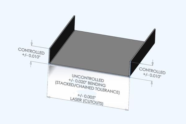
Typical Tolerances for Common Bent Sheet Metal Features
To control final dimensions effectively, we must first establish realistic expectations. Let’s examine the typical manufacturing capabilities for common sheet metal features before addressing why variations occur.
Bend Angles
Standard angle tolerances for most sheet metal parts typically range from ±0.5° to ±1.0°. This applies to standard materials like cold-rolled steel or aluminum up to 3mm thick, processed using standard air bending equipment.
It is important to specify that this angle applies to the finished part in an unloaded, free state. The formed inner angle is not identical to the programmed angle of the press brake punch due to material behavior.
Flanges and Openings
Linear tolerances depend heavily on how the dimension is formed and measured. A single flange, measured from the bend to the cut edge, can usually hold ±0.25 mm to ±0.5 mm.
Dimensions spanning across multiple bends (such as a U-channel opening) or hole-to-hole distances across different planes will inherently carry wider tolerances. Every additional bend introduces dimensional shift. We evaluate these based on material thickness, physical span distance, and backgauge positioning. Applying a single blanket tolerance to all dimensions ignores these physical forming variables.
Capability and General Tolerances
A modern CNC press brake may have a backgauge positioning repeatability of ±0.01 mm, but machine accuracy does not equal final part tolerance. General drawing standards (like ISO 2768) provide a baseline, but they do not guarantee a supplier can hold those numbers for complex bend sequences without specific process controls. Critical features affecting assembly must be evaluated and toleranced individually.
| Feature[cite: 36] | Reference Range[cite: 36] | Applicable Conditions[cite: 36] | Needs Separate Evaluation[cite: 36] |
|---|---|---|---|
| Bend Angles[cite: 36] | ±0.5° to ±1.0°[cite: 36] | Standard materials, thickness ≤ 3mm, short to medium bend lengths[cite: 36] | High-springback materials, very long bends[cite: 36] |
| Single Flanges[cite: 36] | ±0.25 mm to ±0.5 mm[cite: 36] | Measured from edge to bend, backgauge located[cite: 36] | Very short flanges, difficult datum positioning[cite: 36] |
| Openings Across Bends[cite: 36] | Varies by geometry[cite: 36] | Standard measurement height, standard bend sequence[cite: 36] | Deep U-shapes, multiple consecutive bends[cite: 36] |
| Cross-Plane Holes[cite: 36] | Varies by function[cite: 36] | Formed datums, standard inspection methods[cite: 36] | Strict alignment or tight mating clearances[cite: 36] |
Why Bend Angles and Dimensions Vary?
Even with precise machine programming, final dimensions often drift due to physical forming constraints. Understanding these underlying variables helps engineers design more stable parts and avoid unnecessary costs.
Material and Springback
Sheet metal is not perfectly uniform. A 2mm steel sheet will have slight thickness variations within its commercial tolerance range (e.g., 1.90 mm to 1.98 mm). Because bending relies on downward pressure into a fixed die opening, variations in thickness alter the required forming force and shift the final angle.
Springback occurs when the punch releases the material. Springback varies significantly by alloy. For example, 5052-H32 aluminum requires less overbending than 304 stainless steel, which exhibits substantial springback due to its high yield strength and work-hardening properties. Even different mill batches of the same 304 grade can behave differently on the press brake depending on the rolling grain direction.
Bend Development
The flattened blank size dictates the final formed dimensions. This relies on the accurate calculation of the inside bend radius, bend allowance, and bend deduction.
Standard K-factors provided by CAD software (usually around 0.44) are only starting points. Actual material elongation changes based on the specific V-die width and punch tip used on the shop floor. For critical dimensions, the bend deduction must be determined through physical test bends using the exact material and tooling combination. This is why approving a First Article Inspection (FAI) part is critical before laser cutting the entire production run of blanks.
Tooling and Positioning
Physical forming conditions directly impact accuracy. Worn dies, inconsistent contact with the backgauge, or machine deflection during high-tonnage bends all introduce error. Long parts may also require specialized support during bending to prevent the weight of the material from distorting the angle.
The chosen bending method also plays a major role. Air bending is the industry standard due to its flexibility, but it is sensitive to material variations. Bottom bending and coining force the material into the exact shape of the die, reducing springback. However, buyers should note that bottoming requires significantly higher tonnage and angle-specific tooling, which directly increases setup time and unit cost. The resulting die marks may also require additional surface finishing, making these methods cost-effective only when precise angles are strictly required and appearance is secondary.
How Bend Errors Affect Fit and Assembly?
Even when individual bends are within tolerance, components may still fail to mate during assembly. Let’s look at how isolated deviations compound to cause physical interference.
Angular Error
A small angular error at the bend line magnifies over distance. For example, if a 100 mm straight flange is off by just 1°, the tip of that flange will deviate laterally by approximately 1.75 mm. This lateral offset is often enough to cause a standard M4 clearance hole to completely miss its target, even if the overall vertical height of the flange remains within spec.
Tolerance Stack-Up
Parts with multiple bends suffer from tolerance stack-up. Consider a simple U-bracket: the final opening width is determined by the bottom web dimension, the length of both side walls, and the angular accuracy of two separate bends. In a worst-case scenario, if both side walls lean inward by 1°, the opening shrinks significantly. Evaluating this requires calculating the specific dimensional chain, not simply adding a fixed error value per bend. To mitigate this, the best engineering practice is to use slotted holes on one side of the mating component rather than forcing the press brake operator to chase an unrealistic ±0.2 mm tolerance across multiple bends.
Final Assembly Condition
A formed part is rarely the final product. Welding heat causes distortion, while processes like powder coating add 0.05 mm to 0.15 mm of unpredictable material thickness per surface. When designing, ensure your mating clearances account for these downstream operations. You must also explicitly state on your drawing whether the tolerances apply to the bare metal part directly off the press brake, or the finished part after coating and hardware insertion.

Define Functional Tolerances Clearly on Your Drawings
To ensure parts fit, your drawing must translate assembly requirements into measurable constraints. Here is how to specify tolerances that eliminate ambiguity on the shop floor.
Functional Datums
Select your datums based on how the part actually installs, using primary mating faces or critical mounting holes. Do not confuse functional datums with machining datums (like the cut edge used against the backgauge). The manufacturer may alter their positioning strategy to suit their tooling and bend sequence, but the final inspected part must always align with the functional datums defined on your drawing.
Dimension Definitions
Ambiguous dimension lines lead to rejected parts. Clearly define whether a dimension applies to the inside or outside of the material, and specify if measurements refer to the tangent of the bend radius or a theoretical sharp intersection. For U-shapes or enclosures, always define the exact height at which the opening width should be measured.
Critical Features
Applying tight tolerances globally increases part cost without adding value. Restrict strict tolerances exclusively to features that dictate location, fit, sealing, or motion. In many cases, using Geometric Dimensioning and Tolerancing (GD&T)—such as the true position for a hole pattern—communicates the assembly intent much clearer than a block of rigid ± linear dimensions. It provides a cylindrical tolerance zone instead of a restrictive square one, giving the factory up to 57% more manufacturing breathing room without compromising the final fit.
Drawing Release Checklist:
- Does the PDF 2D drawing revision exactly match the exported STEP 3D model?
- Are formed dimensions clearly stated as the final requirement?
- Is the flat pattern marked as “Reference Only”? (Let the manufacturer calculate the blank size based on their specific tooling).
- Is there a defined rule for document conflicts (e.g., “3D model governs for geometry, 2D drawing governs for tolerances”)?
Improve Bend Accuracy Without Unnecessary Manufacturing Costs
Achieving high precision does not always mean paying a premium. Smart design choices and process planning can improve accuracy while keeping production costs down.
Bend Sequence
The order of bends dictates which dimensions are controlled directly by the backgauge and which are indirect “stack-ups.” For example, bending the outer flanges of a U-bracket first might control the overall width perfectly. However, the ideal bend sequence is often restricted by potential tool collisions, machine bed clearances, and backgauge accessibility. Manufacturers must balance your dimensional priorities with these physical tooling limits.
Stable Geometry
Design parts that are naturally stable to form. Use a single inside bend radius across the entire part to eliminate tool changes and setup errors. Ensure flange lengths meet the minimum requirement for the chosen V-die (usually 4x the material thickness) so the sheet sits flat during bending. As a rule of thumb, keep hole edges at least 2.5 to 3 times the material thickness away from the start of the bend radius to prevent distortion, and always include proper bend reliefs to stop the material from tearing.
Process Choices
When tolerances are tight, you face three paths: optimize the bending process, adjust the assembly design, or add post-bend machining. Active angle measurement on the press brake reduces scrap but increases cycle time. CNC machining holes after bending guarantees perfect alignment, but it requires custom fixturing and extra setups, often increasing the cost per part by 30% to 50% or more. Choose the path that matches your functional needs and budget.
| Manufacturing Challenge[cite: 37] | Potential Solution to Evaluate[cite: 37] | Required Trade-Offs[cite: 37] |
|---|---|---|
| Difficult cross-bend hole alignment[cite: 37] | Adjust locating datums or CNC machine after bending[cite: 37] | Added fixturing, +30-50% machining costs vs. perfect hole precision[cite: 37] |
| Interference during opening assembly[cite: 37] | Reallocate tolerances or increase mating clearance[cite: 37] | Positioning accuracy vs. visual appearance and function[cite: 37] |
| Angle drift after a material batch change[cite: 37] | Perform test bends and parameter correction[cite: 37] | Increased machine setup time vs. reliable process stability[cite: 37] |
| Overly strict non-critical dimensions[cite: 37] | Relax corresponding tolerances[cite: 37] | Lower cost vs. zero impact on final assembly[cite: 37] |
Inspect Formed Parts and Verify Production Consistency
Quality control requires clear, repeatable inspection methods. Here is how to ensure your sheet metal parts meet specifications consistently across production runs.
Measurement Setup
Select the right tool for the required tolerance. While calipers and digital protractors handle standard flanges and angles, complex profiles might require a dedicated inspection fixture or a Coordinate Measuring Machine (CMM). Always specify exactly where to measure—such as a specific height along a U-channel—because the opening width will naturally vary depending on how far from the bend the measurement is taken.
Free and Restrained States
Sheet metal is inherently flexible. A large, thin panel might bow slightly under its own weight, causing it to fail a flatness or dimensional check in a “free state.” If the part will be bolted down in its final assembly, specify a “restrained state” inspection. Define the exact support points and clamping sequence on the drawing so the factory measures the part exactly how it will be used. This can include specifying torque values for fasteners or a simple drawing note (e.g., “apply 10N clamping force here”).
First Articles and Repeatability
A perfect First Article Inspection (FAI) proves the program and setup are correct, but sheet metal requires ongoing monitoring. Variations in material batches or tool wear can cause dimensions to drift over time. Depending on your production volume and risk level, establish a clear sampling plan to verify batch-to-batch repeatability, and require a new setup verification whenever the material lot or tooling changes.
Ready to optimize your next sheet metal project?
Submit your drawings and clearly highlight your mounting faces, mating holes, and critical dimensions. The engineering team at Shengen will perform a comprehensive DFM (Design for Manufacturing) review of your part structure, evaluate your bend tolerances, determine the most stable processing sequence, and align on inspection requirements to ensure a perfect fit without unnecessary costs.
Hey, I'm Kevin Lee

For the past 10 years, I’ve been immersed in various forms of sheet metal fabrication, sharing cool insights here from my experiences across diverse workshops.
Get in touch
Kevin Lee
I have over ten years of professional experience in sheet metal fabrication, specializing in laser cutting, bending, welding, and surface treatment techniques. As the Technical Director at Shengen, I am committed to solving complex manufacturing challenges and driving innovation and quality in each project.