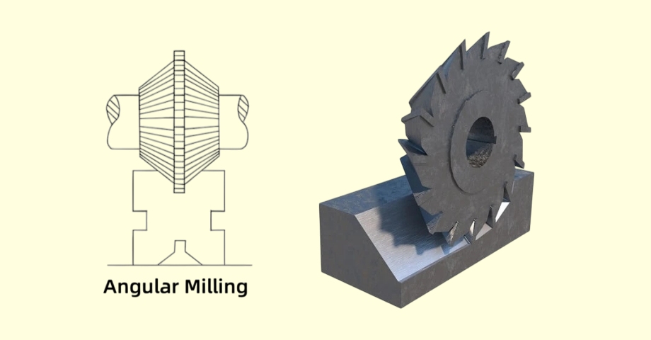
Angular milling (or angle milling) is a CNC machining process used to create flat surfaces, chamfers, or grooves at a specified non-perpendicular angle to the workpiece axis. This is achieved using specialized angle cutters, tilted fixtures, or multi-axis machine movements.
In CAD, drawing a 45° chamfer or a 60° dovetail slot takes only a few clicks. On the shop floor, however, these angular features require entirely different manufacturing approaches.
This guide breaks down the practical methods, tool selection, DFM rules, and cost drivers for angular milling, helping you design manufacturable parts and secure accurate quotes.
Choose the Right Angular Milling Method
Different part features dictate different machining strategies. Evaluating the method early helps avoid unnecessary tooling costs or excessive setup times on the shop floor.
Angled Cutters
In this approach, the machine operates in standard XYZ axes, and the fixed profile of the cutter creates the angle. This method is usually used for standard edge chamfers, symmetrical V-grooves, and specific formed features like dovetails where the cutter’s geometry directly matches the print.
While it seems straightforward, it is not automatically the lowest-cost option. You must verify that the cutting width covers the feature and there is sufficient clearance for the tool body. If your design requires a non-standard angle, custom angled cutters can add 150 to 300 in tooling costs and 1 to 2 weeks of lead time, which is rarely cost-effective for low-volume prototypes.
Tilted Setups
Instead of using a specialized cutter, this method tilts the workpiece or adjusts the machine head, allowing a standard flat or ball end mill to machine the sloped surface. This works well for large angled faces, such as weld bevels, where an angled cutter would be too small or prone to chatter.
However, setup time and fixture stacking become the main constraints. When using a tilted setup with a sine plate, stacking multiple fixtures can introduce angular runout. Achieving a standard ±0.5° tolerance is routine, but holding a ±0.1° tolerance across a long mating bevel often requires dedicated custom-machined soft jaws and on-machine probing to verify the exact datum plane.
Multi-Axis Options
Multi-axis machining handles angles by changing the orientation of the spindle relative to the part. It is important to distinguish between 3+2 positional machining, which locks the axes at a specific angle for standard tool paths, and full 5-axis simultaneous milling, which is reserved for continuous, sweeping angles.
3+2 machining reduces the number of manual setups and improves feature-to-feature positional accuracy, making it ideal for complex parts with multiple compound angles. While multi-axis machining carries a higher machine rate—often 20% to 40% higher than standard 3-axis routing—eliminating secondary manual setups usually makes it the most cost-effective option for production runs over 100 parts.
Method Comparison on a 15-Degree Bracket:
To machine a single 15-degree mating face: An angled cutter is limited by max tool diameter and requires custom tool lead time. A tilted setup requires a sine plate and manual tramming, which is practical for 10 prototype parts. 3+2 Multi-axis machining carries a higher hourly rate but completes the part in one setup, making it the clear choice for volume production.
Match the Cutter to the Feature
Selecting an angular milling cutter requires more than matching the angle on the print. The tool must form the target profile while safely clearing the rest of the workpiece.
Cutter Profiles
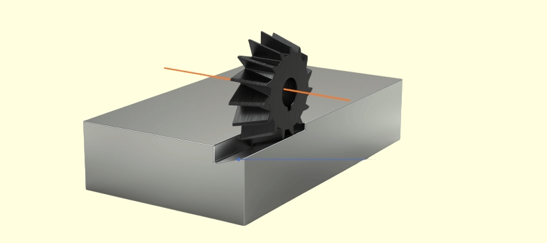
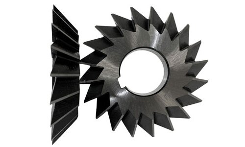
Different angular features require specific tool geometries to execute properly. Single-angle cutters have teeth on one conical face and are typically used for asymmetrical chamfers or machining the side walls of dovetail slots. Double-angle cutters feature V-shaped profiles, making them suitable for machining symmetrical V-grooves and thread milling operations.
When selecting these tools, check the manufacturer’s specifications carefully against the engineering drawing. A common shop floor error is confusing a tool’s included angle with its half-angle, or misinterpreting the intended part surface angle, which can result in scrapping an entire batch of parts.
Tool Clearance
Checking tool clearance means evaluating the entire tool assembly, not just the cutting edge. You must verify the spatial relationship between the flutes, tool neck, tool holder, and the workpiece or fixture. For deep slots or features near tall vertical walls, the fact that the cutting edge can touch the target surface does not guarantee that the tool holder will clear the adjacent geometry.
This clearance evaluation must include the actual cutting position as well as the programmed entry and exit paths. If a dovetail cutter has to retract suddenly to avoid a clamp, the CAM simulation must account for the non-cutting diameter of the tool shank to prevent catastrophic collisions.
Material Compatibility
The workpiece material directly dictates the required tool substrate, edge preparation, and coating. For example, milling angles in Aluminum 6061 requires sharp, polished carbide flutes to prevent built-up edge, while cutting 304 Stainless Steel requires specialized coatings like TiAlN and highly rigid setups to manage heat and resist work hardening.
Furthermore, angled cutters face unique physical challenges during machining. The tip of a V-cutter has an effective diameter close to zero, meaning the surface speed (SFM) drops drastically at the bottom of the cut. This makes chip evacuation difficult and often leads to premature tool chipping when machining harder alloys, requiring strict control over tool stick-out and feed rates.
Design Angular Features for Easier Machining
Minor design modifications can eliminate the need for specialized cutters, secondary setups, or complex 5-axis programming. Evaluating angular features during the Design for Manufacturability (DFM) phase helps keep production costs predictable.
Standard Angles
Whenever functional requirements allow, prioritize standard angles like 30°, 45°, 60°, or 90°. These angles match off-the-shelf tooling available in almost any machine shop, allowing production to start immediately without custom tooling delays.
Specifying a non-standard angle, such as 47.5°, drastically changes the manufacturing approach. The shop must either order a custom-ground cutter, adding lead time, or use a 3D surfacing toolpath on a multi-axis machine, which significantly increases cycle time. While a non-standard angle does not always mean a massive cost increase, it forces the manufacturer to use slower or more expensive methods.
Corner Relief
Machining a perfectly sharp inside corner at the bottom of a V-groove or a dovetail is physically impossible with rotating tools. The cutter tip will always leave a micro-radius or a small flat. If an angular mating part needs to sit flush inside the groove, this inevitable micro-radius will cause the mating part to high-center, leading to immediate assembly interference and mating failure.
Instead of demanding an unmachinable sharp corner, design a “dog-bone” relief or a small clearance undercut at the vertex. By clearly indicating which angled surfaces actually need to make physical contact, you prevent the manufacturer from wasting time trying to achieve tight tolerances in non-functional clearance zones.
Accessible Geometry
Angle cutters need physical space to enter and exit the cut. A common issue occurs when a deep angular slot terminates directly into a tall adjacent wall. When approaching this blind wall, the CNC machine must drastically decelerate the feed rate to prevent over-cutting. This deceleration causes the tool to rub rather than cut, killing tool life and destroying the surface finish.
You can resolve this by widening the local opening, changing a closed-end slot to a run-out slot that exits the edge of the part, or slightly reducing the feature depth. These modifications preserve the mechanical function of the slot while removing severe tool clearance and feed-rate limitations.
Control Chatter, Chips, and Tool Wear
Angular milling generates complex cutting forces that can quickly compromise part quality. Stabilizing the process requires managing tool deflection, clearing chips effectively, and monitoring wear patterns.
Support and Rigidity
Because angle cutters engage the material on a slope, they generate significant lateral (side-pushing) forces. For thin-walled parts or unsupported overhangs, this lateral force causes the material to flex away from the cutter, resulting in severe chatter marks and dimensional inaccuracies.
To counter this, evaluate workpiece support directly behind the angled cut before blaming tool holder rigidity. Ensure the fixturing setup provides solid mechanical backing, and differentiate between clamps (which primarily hold the part down against Z-axis lift) and locators (which absorb the heavy X/Y lateral pushing forces generated by angle cutters).
Cutting Strategy
Never plunge an angled form cutter directly into solid material. Because the cutting edge varies in diameter, the cutting load is unevenly distributed, which can instantly snap fragile tool tips.
For features like dovetail slots, always use a standard flat end mill to rough out the central rectangular channel first. This creates an open entry space so the dovetail cutter only machines the actual target angled sidewalls. When setting parameters, base your spindle speeds and feed rates on the tool’s effective cutting diameter at the point of maximum engagement, rather than the maximum nominal tool diameter.
Chips and Wear
In deep V-grooves or steep angled pockets, chips often fail to evacuate and fall back into the cutting zone. Recutting these chips is the leading cause of sudden tool chipping. In work-hardening materials like 304 stainless steel or titanium, rubbing a recut chip against the part creates a localized hardened zone that will instantly destroy the tool on its next pass.
Verify that the chip evacuation path is clear and adjust coolant nozzles accordingly. A standard flood coolant may simply push chips back into a blind slot; using Through-Spindle Coolant (TSC) or a targeted high-pressure air blast is far more effective. In production runs, track early signs of tool wear by monitoring burr formation and minor dimensional drift, allowing you to change tools before the surface finish degrades.
| Symptom[cite: 38] | Primary Check[cite: 38] | Verification / Fix[cite: 38] |
|---|---|---|
| Heavy Chatter Marks[cite: 38] | Workpiece support & lateral forces[cite: 38] | Add physical locators behind the cut to absorb X/Y pushing forces; use a shorter tool holder.[cite: 38] |
| Varying Chamfer Width[cite: 38] | Z-axis datum & part flatness[cite: 38] | Indicate the reference surface before cutting; check for chips trapped under the fixture.[cite: 38] |
| Chipped Cutter Tip[cite: 38] | Chip evacuation & pre-machining[cite: 38] | Ensure the center channel is pre-roughed; switch to high-pressure air blast to prevent chip recutting.[cite: 38] |
| Gradual Dimension Drift[cite: 38] | Tool wear & thermal expansion[cite: 38] | Measure parts at consistent temperatures; apply CAM cutter compensation for edge wear.[cite: 38] |
Define Tolerances and Verify Angular Features
Drawing an angle in CAD is straightforward; verifying that the machined physical surface matches the drawing requires clear tolerancing and the right metrology equipment. Over-tolerancing increases inspection costs, while under-tolerancing leads to assembly failures.
Functional Requirements
Before assigning tolerances, classify the angular feature by its actual function. A simple edge break to remove sharp burrs only needs a loose visual tolerance or a basic MAX/MIN width. An assembly lead-in chamfer requires moderate dimensional control to guide mating parts smoothly.
However, a precision mating bevel or a dovetail rail requires strict control over the angle, location, and surface finish. Clearly separating non-critical clearance angles from functional mating surfaces prevents the manufacturer from wasting expensive CMM (Coordinate Measuring Machine) time on features that do not affect part performance.
Drawing Controls
Specifying just an angle (e.g., 45° ±0.5°) is often insufficient for functional surfaces. A surface can be machined perfectly at 45° but positionally shifted 1mm away from its intended location, causing the assembly to fail. For critical angular features, rely on GD&T (Geometric Dimensioning and Tolerancing), specifically a “Profile of a Surface” callout. This controls the angle, form, and location of the sloped face simultaneously relative to your primary datums.
Additionally, be cautious with surface finish requirements. Specifying an unnecessarily tight surface finish (like Ra 0.8 / 32 µin) on a 3D-surfaced angle forces the CAM programmer to use microscopic step-overs with a ball end mill. This can easily triple the machining time for a feature that might just be cosmetic.
Inspection Methods
The size and tolerance of the angle dictate the inspection method. Measuring a tiny 0.5mm edge chamfer with a CMM probe is highly inaccurate due to the limited contact area. For these micro-features, optical comparators or vision systems provide the most reliable verification on the shop floor.
For larger functional bevels and compound angles, a CMM is the standard. However, the inspection setup must account for probe stylus angles and cosine error. The metrology technician must often calibrate the probe to hit the sloped surface perpendicularly. Furthermore, measuring surface roughness on steep internal angles often requires portable profilometers with articulating styluses, which adds to the overall Quality Control (QC) time.

Compare Costs Before Requesting a Quote
Understanding how angular features impact the manufacturing workflow helps you estimate costs before submitting a Request for Quote (RFQ).
Cost Drivers
The true cost of angular milling is divided across programming, setup, tooling, cutting, and inspection. A single compound angle that requires 5-axis continuous milling increases CAM programming time and requires a machine with a higher hourly rate.
If the angle is hard to reach, it may force the machinist to run at slower feed rates to prevent chatter, extending the cycle time. Furthermore, if the drawing requires a 100% CMM inspection report for a complex compound angle, the QC time per part can sometimes equal or exceed the actual machining time.
Batch Economics
The most cost-effective method shifts dynamically based on production volume. For a prototype run of 5 parts, buying a custom form tool is inefficient; the shop will likely use a standard ball end mill on a 3-axis machine to surface the angle, absorbing the longer cycle time to save on upfront tooling costs and delays.
Conversely, for a production run of 2,000 parts, relying on slow 3D surfacing is economically unviable. The upfront investment in custom-ground carbide form tools and dedicated angled fixtures pays for itself rapidly by reducing the cycle time from minutes down to seconds per part.
RFQ Details
To receive an accurate and competitive quote, your RFQ must provide a clear manufacturing roadmap. Always ensure your 3D CAD model (STEP format) matches your 2D PDF drawing.
A common quoting delay occurs when the 3D model shows a sharp internal angled corner, but the PDF includes a general note stating “All inside radii R0.5”. Explicitly calling out which document takes precedence saves days of engineering clarification. Additionally, indicate any areas where the manufacturer is allowed to adjust corner radii or add tool reliefs, allowing the shop to propose cost-saving DFM adjustments.
Case Study: Optimizing an Optical Mount Dovetail
The Part: An Aluminum 6061 optical mounting bracket featuring a continuous 60° dovetail rail.
The Requirement: The rail required a strict Profile of a Surface tolerance of 0.02mm to ensure smooth sliding without backlash.
Initial Plan: The original RFQ assumed 5-axis machining to guarantee positional accuracy, resulting in a high initial quote.
The Shengen Solution: After a DFM review for a 500-part production run, we moved the part to a rigid 3-axis Vertical Machining Center. We first roughed the center channel with a standard end mill, then finished the precision 60° walls using a custom-ground carbide dovetail cutter in a single pass.
The Result: Using a dedicated form tool eliminated the need for expensive 5-axis machine time and removed all blending marks. The cycle time dropped by 35%, and the $250 upfront cost for the custom dovetail cutter paid for itself within the first 25 parts. Overall, the production batch passed CMM profile inspection with a 100% yield.
Ready to manufacture your precision components? Complex dovetails, compound bevels, and tight-tolerance angles require careful planning and execution. Submit your CAD models, 2D drawings, material requirements, and quantities to Shengen. Our engineering team will evaluate tool accessibility, propose cost-saving DFM modifications, and deliver a competitive manufacturing strategy tailored to your exact functional requirements.
Hey, I'm Kevin Lee

For the past 10 years, I’ve been immersed in various forms of sheet metal fabrication, sharing cool insights here from my experiences across diverse workshops.
Get in touch
Kevin Lee
I have over ten years of professional experience in sheet metal fabrication, specializing in laser cutting, bending, welding, and surface treatment techniques. As the Technical Director at Shengen, I am committed to solving complex manufacturing challenges and driving innovation and quality in each project.