Welding undercut is often miscategorized as a mere cosmetic flaw. However, on the shop floor and in structural engineering, it is treated as a strict mechanical liability. Undercut physically removes base material along the edge of the weld, directly reducing the effective cross-sectional area of the joint.
A welding undercut is a critical groove defect melted into the base metal at the weld toe and left unfilled by filler material. This reduces the part’s cross-sectional thickness and creates sharp stress risers prone to fatigue failure, typically resulting from excessive heat input or overly fast travel speeds.
This technical breakdown examines the physical mechanisms that make undercut dangerous. We will also cover the specific shop-floor variables that trigger it, how to establish stable production controls, and the critical thresholds for deciding whether to repair or scrap a fabricated part.
Why Welding Undercut Becomes a Structural Problem?
Undercut fundamentally alters the geometry and mechanical properties of a welded assembly. When a part fails due to undercut, it is rarely due to a lack of overall weld volume; it fails because the defect specifically compromises the localized structural integrity.
Weld Toe Material Loss
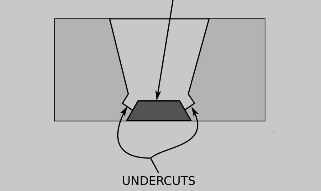
The physical reality of an undercut is a literal loss of base metal. During the welding process, the intense heat of the arc melts the parent material at the weld toe—the critical junction between the weld face and the base metal.
If the filler metal does not properly flow in to replace this melted volume, a permanent groove or trench is left behind. This flaw reduces the designed thickness of the sheet metal exactly at the boundary of the joint, immediately lowering the load-bearing capacity of that specific section.
Stress Concentration
Engineers calculate load distribution based on uniform material thickness and smooth structural transitions. An undercut disrupts this by introducing a sharp, irregular geometric notch directly into the surface.
When tension or bending forces are applied to the welded part, the stress lines cannot flow smoothly through the joint. Instead, they compress and multiply around the root of the undercut. This localized stress concentration forces the metal at the notch to bear a significantly higher load, pushing it dangerously close to its yield strength.
Fatigue Crack Initiation
While a static load might not immediately snap a part with a minor undercut, dynamic loads tell a completely different story. In heavy machinery, vehicle chassis, or pressure vessels, parts undergo continuous vibration and cyclic stress.
The stress concentration at an undercut groove acts as the perfect nucleation site for metal fatigue. Micro-cracks begin to form at the bottom of the notch and propagate through the heat-affected zone (HAZ) over time, leading to premature structural failure long before the component’s expected lifespan.
Shop Floor Causes of Welding Undercut
Undercut is rarely a random occurrence; it is the direct result of a mismatch in welding parameters, operator technique, or material handling. Identifying the root cause requires looking at the balance of heat and material deposition.
Heat Input Balance
The most common trigger for undercut is excessive heat input. When the welding current (amperage) or arc voltage is set too high for the specific sheet metal thickness, the arc digs far too aggressively into the base metal.
This excessive thermal energy melts a wider and deeper trench than intended. Consequently, it creates a cavity that the standard volume of molten filler wire simply cannot fill before the weld puddle freezes.
Filler Metal Deposition Rate
Undercut also occurs when the heat input is adequate, but the filler metal deposition rate is too low. In MIG (GMAW) welding, this typically points to a wire feed speed (WFS) that is out of sync with the voltage.
The arc forcefully displaces the base metal, but the inadequate supply of filler wire leaves the edges starved. This operational mismatch results in a distinct, unfilled groove running cleanly along the upper toe of the weld.
Torch Angle and Arc Force
In manual and semi-automatic welding, the angle of the torch dictates exactly where the arc force is directed. This is highly visible in T-joints and fillet welds. If the work angle is heavily biased toward the vertical plate, the arc will gouge the vertical surface.
Gravity then pulls the molten weld pool downward before it can wet into the vertical gouge. This leaves a prominent undercut on the top edge of the joint. Maintaining a balanced work angle and a slight drag angle (typically 10° to 15°) is required to properly distribute the heat and push the filler metal into the toes.
Travel Speed Stability
An inconsistent travel speed rapidly destabilizes the weld pool dynamics. Moving the torch too fast is a frequent error; the arc force gouges the metal, but the fast travel speed prevents the molten puddle from keeping up and washing into the edges of the weld.
Conversely, moving too slowly can cause excessive heat buildup in a localized area. This overly melts the base metal and causes the puddle to spill out or collapse, effectively dragging material away from the weld toes rather than filling them.
Material and Process Sensitivity
Material selection directly impacts undercut sensitivity. A base metal’s specific thermal conductivity and molten puddle fluidity determine exactly what happens at the joint edge the moment welding parameters drift off target.
MIG Welding Behavior
MIG (GMAW) welding is highly susceptible to undercutting due to its reliance on the strict synchronization of voltage and wire feed speed. When operating in spray transfer mode, the arc is incredibly forceful and hot, designed for deep penetration on thicker plates.
If the operator’s travel speed exceeds the deposition rate of the filler wire by even 10% to 15%, this high-energy arc essentially excavates a trench. The filler wire simply cannot melt fast enough to fill the void. This makes MIG highly sensitive to travel speed, especially on automated robotic tracks where parameters are locked but minor joint variations occur.
Aluminum Weld Pool Flow
Aluminum presents a unique challenge because its thermal conductivity is roughly five times greater than that of carbon steel. The metal rapidly pulls heat away from the weld zone. To compensate, operators often increase the amperage, but molten aluminum has a very low viscosity—it flows almost like water.
If the arc force is too high, this highly fluid puddle is easily blown out of the joint. Because the surrounding metal cools the edges so rapidly, the displaced molten aluminum freezes before it can flow back and wet into the toes, leaving a sharp undercut.
Stainless Steel Heat Response
Unlike aluminum, stainless steel grades (such as 304 and 316) have poor thermal conductivity, causing the heat from the arc to stay intensely localized. Furthermore, molten stainless steel is inherently sluggish and highly viscous.
When too much heat is applied (e.g., exceeding a heat input of 1.5 kJ/mm on thin sheets), the base metal at the weld toe melts away. However, the thick, sluggish weld pool does not easily wash outward to fill the void. This localized overheating combined with poor puddle fluidity makes stainless steel highly prone to undercutting, requiring precise parameter control and often specialized shielding gas mixtures to improve surface tension.
Defect Prevention: Shop Floor Production Controls
High-tier mass manufacturing facilities do not rely on “fixing” undercut; they engineer the process to prevent it. Eliminating this defect requires shifting the focus from the welding booth back to the process engineering and upstream preparation stages.
WPS Parameter Control
Stable manufacturing relies on eliminating operator guesswork. Every structural weld must be executed according to a validated Welding Procedure Specification (WPS).
A strict WPS defines the exact ±5% operating window for amperage, voltage, travel speed, and gas flow for a specific material thickness. By forcing operators to stay within these engineered parameters, the factory mechanically prevents the heat-to-wire imbalances. This strict adherence slashes manual rework costs by ensuring a high first-pass yield.
Fit-Up Consistency
Many undercuts are actually caused in the laser cutting or press brake department, not by the welder. Poor part fit-up creates inconsistent joint gaps. For instance, if a gap exceeds 1.5mm or 10% of the material thickness on a thin sheet, the operator is forced to slow down and weave the torch excessively to bridge the void.
This localized lingering pumps uncontrolled heat into the base metal, inevitably melting away the toes. Tightly controlled laser-cutting tolerances upstream are the most cost-effective way to eliminate welding rework downstream, drastically improving overall production ROI.
Surface Preparation
Surface contaminants physically alter how the molten puddle behaves. Mill scale, heavy oxides, cutting fluids, or rust can drastically change the surface tension of the base metal, preventing the molten filler metal from smoothly washing into the joint edges.
Mandating strict mechanical cleaning to remove oxides at least 10mm to 15mm back from the joint edge is critical. This clean zone prevents the arc from wandering and aggressively biting into the toes, ensuring the puddle wets out perfectly flush with the parent metal.
Real-Time Process Monitoring
In modern rapid prototyping and automated fabrication, relying solely on post-weld visual inspection is a costly liability. Advanced production lines utilize real-time arc monitoring systems that continuously track voltage and amperage micro-fluctuations in milliseconds.
If the system detects a voltage spike (indicating the arc length has increased and is gouging the metal), it automatically adjusts the wire feed speed or triggers an immediate halt. This closed-loop control catches the exact conditions that cause undercut, consistently reducing high-volume scrap rates by over 30% and keeping the cost-per-part strictly under control.
Defect Identification: Inspection Standards and Repair Tradeoffs
Rewelding should never be the default reaction to an undercut. Subjecting a minor defect to a second heat cycle often degrades the structure more than the original flaw.
Practical Visual Inspection Limits
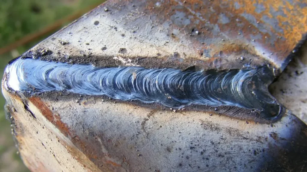
The first line of defense is a thorough visual inspection using a calibrated V-WAC (Visual Weld Acceptance Criteria) gauge. Because undercut blends into the toe of the weld, it is notoriously difficult to eyeball on a busy shop floor.
A practical, immediate rule is the “fingernail test”—if a fingernail catches cleanly in the groove along the weld toe, the defect has a sharp enough notch acuity to warrant physical measurement. At this stage, the exact depth and length of the undercut must be recorded against the engineering drawings to determine the next step.
AWS and ISO Tolerances
Acceptance criteria are strictly defined by international standards, not personal opinion or operator preference. Under AWS D1.1 (Structural Welding Code – Steel), an undercut depth of up to 1mm (1/32 inch) might be acceptable for statically loaded, non-critical structures.
However, for cyclically loaded parts where fatigue is the primary failure mode, the tolerance drops drastically. ISO 5817 Level B (the highest quality level) dictates that undercut must not exceed 0.5mm. In highly critical aerospace or dynamic-load applications, the tolerance is absolute zero.
NDT Verification
Visual inspection is useless for internal or root undercut, particularly in deep penetration joints, heavy structural tubing, or pipe configurations. For high-stress structural sheet metal or pressure-retaining components, Non-Destructive Testing (NDT) is mandatory.
Techniques like Ultrasonic Testing (UT) or Radiographic Testing (RT) are deployed to look beneath the surface. UT is exceptionally effective at bouncing sound waves off the hidden geometry of a root undercut, giving engineers exact, quantifiable data on the internal effective thickness loss.
Mechanical Blending vs. Rewelding
When an undercut falls slightly outside acceptable tolerances (e.g., measuring 0.6mm when the limit is 0.5mm), the immediate instinct is often to add a quick weld pass. This is frequently a mistake.
If the base metal is thick enough, mechanical blending with a carbide burr or flap disc is heavily preferred. Grinding out the sharp notch into a smooth, radiused transition (typically a 3:1 or 4:1 taper) completely removes the stress concentration. Mechanical blending is significantly cheaper, faster, and structurally safer than subjecting the part to another blast of extreme heat.
When Rewelding Creates New Problems
When a repair weld is absolutely mandated by the code, it must be treated as a highly invasive procedure. Pumping localized heat back into a finished joint permanently alters the metallurgy and dimensional stability of the entire assembly.
HAZ Degradation
Every single weld creates a Heat-Affected Zone (HAZ)—an area of base metal that was not melted but had its microstructure permanently altered by extreme heat.
Rewelding an undercut expands this HAZ significantly. In materials like 304 stainless steel or high-strength low-alloy (HSLA) steels, this secondary thermal shock causes severe grain growth and carbide precipitation. The physical result is a localized loss of tensile strength, decreased impact toughness, and a drastic drop in corrosion resistance right at the joint edge.
Repeated Heat Cycles
Metals have a strict thermal memory. Subjecting a specific location to a secondary thermal cycle (heating, melting, and rapid cooling) fundamentally changes its mechanical properties.
In carbon steels, the rapid cooling from a small, localized repair weld can cause the formation of brittle martensite. While the undercut groove might now be physically filled and visually acceptable, the repair has secretly created a highly brittle, crack-sensitive zone exactly where the dynamic load stress will be highest.
Distortion and Residual Stress
Adding a repair pass means adding more molten filler metal, which inherently shrinks as it cools. This introduces massive, localized residual shrinkage forces into the component.
Particularly in sheet metal fabrication, this secondary heat cycle causes severe warping and angular distortion. A part that initially failed a visual weld inspection might pass the welding rework, only to immediately fail dimensional tolerance checks at the final QC station because the chassis or enclosure is now permanently warped.
Conclusion
Welding undercut is more than a surface defect. It changes the weld toe geometry, reduces effective material thickness, and increases stress concentration in loaded structures. In production environments, even a small undercut can lead to fatigue cracks, inspection failures, rework costs, or shortened service life.
Stable welding quality does not come from trial-and-error adjustments on the shop floor. It depends on controlled welding parameters, consistent fit-up, proper surface preparation, and process validation before full production begins.
At Shengen, we help customers reduce welding defects during both prototyping and mass production. Our engineering team reviews weld joint design, material selection, fit-up conditions, and manufacturing parameters before production starts. Send us your drawings or project requirements to discuss your next welded fabrication project.
Hey, I'm Kevin Lee

For the past 10 years, I’ve been immersed in various forms of sheet metal fabrication, sharing cool insights here from my experiences across diverse workshops.
Get in touch
Kevin Lee
I have over ten years of professional experience in sheet metal fabrication, specializing in laser cutting, bending, welding, and surface treatment techniques. As the Technical Director at Shengen, I am committed to solving complex manufacturing challenges and driving innovation and quality in each project.


