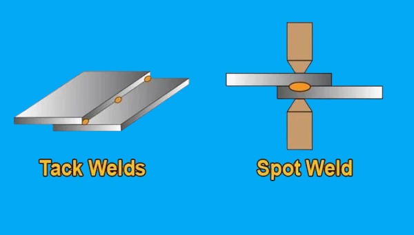
In sheet metal fabrication, tack welding and spot welding are often used in the same production line, but they solve completely different manufacturing problems.
Tack welds are non-structural, temporary fusion spots designed solely to maintain assembly alignment prior to final welding. In contrast, spot welds are permanent, high-strength structural joints formed via resistance and pressure, specifically engineered to fuse overlapping sheet metal without filler material.
Choosing the wrong process for your production stage directly impacts tooling costs, cycle times, and ultimate part quality. Here is a practical, shop-floor breakdown of how these two processes function and where they belong in your manufacturing workflow.
Why Tack Weld and Spot Weld Are Often Confused?
On the surface, both processes create small, localized connections rather than continuous seams. This visual similarity often leads to confusion during the design and procurement phases. However, their engineering functions and the physics driving them are entirely different.
Localized Weld Points
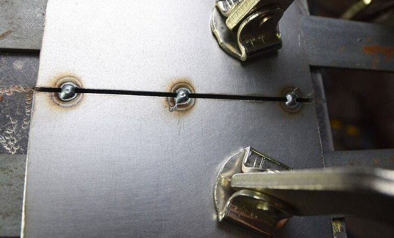
To an untrained eye, both processes result in isolated “dots” holding two pieces of metal together. A tack weld is typically a short burst of a traditional arc welding process (like TIG or MIG), depositing a small amount of filler metal onto the surface.
A spot weld, utilizing resistance welding, uses copper electrodes to clamp the metal and pass a high current through it. This melts the sheets together from the inside out. Both leave a small footprint, but the mechanics behind them share zero overlap.
Temporary vs Permanent Joining
This is the fundamental divide in purpose. A tack weld is strictly a temporary hold. Its only job is to keep components from shifting before the final, structural weld is applied.
A spot weld, conversely, is the final operation. Once the copper electrodes release, that joint is permanent and designed to bear the structural load dictated by the engineering drawing.
Assembly Workflow
The two processes live in entirely different phases of manufacturing. Tack welding belongs to the “fit-up” stage—it is an intermediate step where fitters lock the geometry of a complex chassis or frame before sending it to a welding booth.
Spot welding is a dedicated assembly cell operation. Parts enter a spot welding station, get fused instantly, and immediately move on to finishing or shipping.
Why Tack Welding Controls Assembly Accuracy?
When dealing with sheet metal enclosures or structural frames, heat is the enemy of dimensional accuracy. Tack welding acts as the primary mechanical defense against thermal distortion during the main welding phase.
Tack Spacing
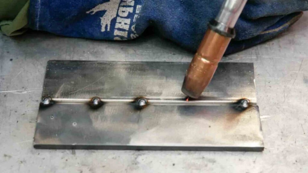
Tacks must be strategically placed to counteract warping. If the tacks are placed too far apart, the heat of the main continuous weld will cause the sheet metal to buckle or bow between the points.
The standard shop rule is to space tacks based on the material thickness and the total anticipated heat input of the final bead. This ensures the joint remains rigid throughout the entire heating and cooling cycle.
Gap Alignment
Perfect fit-up is extremely rare in real-world fabrication. Tack welding allows operators to manually push, pull, and clamp slightly warped components into strict tolerance limits, locking in the root gap.
This manual alignment ensures the main weld penetrates evenly. It prevents the arc from burning through wide gaps or failing to fuse tight, misaligned corners.
Distortion Control
When you lay down a long, continuous weld bead, the metal expands rapidly and then shrinks as it cools, pulling the assembly out of square.
By placing small, low-heat tack welds at critical junctions first, you create a rigid skeleton. This locks the geometry in place, forcing the material to resist its own internal thermal stresses during final welding.
Defect Transfer
A critical reality on the shop floor is that a bad tack ruins a good weld. Because tack welds are usually consumed (melted over) by the final weld bead, any defect in the tack—such as porosity, cold lap, or trapped slag—will transfer directly into the final joint.
Therefore, high-quality fabrication requires tacks to be executed with the same parameter control as the primary weld. Often, they must be ground down to clean metal before the final pass begins.
Fixture Dependency
Custom tooling and heavy-duty clamping jigs are expensive and take weeks to machine. Tack welding drastically reduces the need for complex, dedicated hard tooling.
A skilled fabricator can use standard modular clamps to hold the pieces, shoot a few well-placed tacks, and immediately remove the clamps. The tacked assembly now acts as its own fixture, freeing up workspace and accelerating the prototyping cycle.
Why Spot Welding Fits High-Volume Production?
While tack welding is the hero of custom fit-ups, spot welding is the undisputed engine of mass manufacturing. It strips away the manual variables of arc welding, replacing them with speed, consistency, and highly repeatable cycle times.
Weld Nugget Formation
Spot welding does not rely on an external electric arc or filler wire. Instead, it uses the natural electrical resistance of the sheet metal itself. High current is forced through copper electrodes clamping the workpieces, generating intense heat that melts the metal from the inside out.
This creates an internal weld nugget that fuses the sheets together beneath the surface. Because the melting is completely contained and pressurized, the process is incredibly fast—typically taking only 0.1 to 0.5 seconds per weld—and requires absolutely zero shielding gas or filler material.
Robotic Welding
The mechanics of spot welding make it exceptionally easy to automate. Whether using a stationary pedestal welder or a 6-axis robotic arm, the machine only needs to clamp, apply current, and release.
This eliminates the need for complex torch angles or travel speeds required in robotic arc welding. In high-volume sheet metal fabrication, a robotic spot welding cell can execute hundreds of reliable structural joints per minute, drastically outpacing manual assembly.
Marginal Part Cost
Once the initial capital expenditure for the spot welding equipment and fixtures is amortized, the marginal cost per part plummets to near zero. You are essentially only paying for the electricity and the operator’s time to load and unload the machine.
Because there are no expensive consumables—like argon gas, tungsten, or spools of welding wire—spot welding is the most cost-effective joining method for continuous production runs exceeding thousands of units.
Electrode Wear
However, spot welding is not entirely free of maintenance costs. The primary shop-floor consumable is the copper electrode itself. Under immense heat and pressure, the copper tips eventually flatten (mushrooming) or become contaminated by the workpiece.
This electrode wear changes the contact area, dropping the current density and leading to weak, undersized weld nuggets. To maintain quality, operators must routinely stop production for electrode dressing (reshaping the tips), which must be factored into cycle time calculations.
Surface Indentation
A defining physical characteristic of spot welding is the surface indentation, or “dimple,” left behind by the clamping pressure of the electrodes. While structurally sound, this mark is highly visible on the exterior of the metal.
If the component requires a flawless cosmetic finish—known as an A-surface on consumer enclosures or appliances—these indentations will require secondary grinding and filling. For visible panels, engineers must weigh the speed of spot welding against the added labor of surface finishing.
Tack Weld vs Spot Weld in Production
When moving a product from the prototype phase into full production, engineers must evaluate how the chosen joining method will affect the structural integrity and the workflow on the factory floor. Understanding the hard limits of both processes prevents costly redesigns and assembly bottlenecks down the line.
Joint Geometry Requirements (DFM)
This is the most critical design constraint. Tack welding is geometrically flexible; a welder can tack together butt joints, corner joints, or fillet joints with ease.
Spot welding, however, is strictly limited to lap joints (where two sheets overlap). If an engineer intends to use spot welding for an enclosure, the sheet metal flat pattern must be designed with overlapping flanges to accommodate the electrodes.
DFM Pro Tip: When designing flanges for robotic spot welding, always allow for a minimum flange width of 2 to 3 times the spot weld nugget diameter. This provides enough edge distance to prevent the molten metal from blowing out the side of the flange.
Joint Strength
A tack weld is intentionally designed to be weak; it only needs enough tensile strength to withstand handling and thermal stress before the final weld is completed. It is not a structural joint and will fail under continuous load or vibration.
A spot weld, on the other hand, is a permanent, load-bearing connection. When executed correctly, a spot-welded joint is often stronger than the surrounding base metal. In a destructive peel test, the metal sheet should tear before the weld nugget actually breaks.
Material Thickness Limits
Tack welding is a universal tool. Because it utilizes standard arc welding processes (TIG/MIG), a skilled welder can tack together anything from ultra-thin sheet metal to massive, multi-inch thick structural brackets by simply adjusting the machine’s amperage.
Spot welding is strictly limited to thin gauge materials, typically between 0.5mm and 3.0mm (24 to 11 gauge). If the metal is thicker than 3.0mm, standard equipment cannot generate enough localized resistance heat to melt a consistent internal nugget before the copper electrodes overheat.
Rework Difficulty
Mistakes happen on the shop floor, and rework is a reality of manufacturing. A misplaced tack weld is relatively easy to fix. An operator can quickly slice through the small tack with an angle grinder, separate the parts, and re-align them without destroying the base material.
A misplaced spot weld is a destructive problem. To separate spot-welded sheets, you must physically drill out the entire weld nugget using a specialized spot weld drill bit. This leaves a permanent hole in one of the sheets, often rendering the part scrap and increasing material waste.
Material Limits in Tack and Spot Welding
Not all metals behave the same under an electric arc or between copper electrodes. Material science dictates which process will flow smoothly on the shop floor and which will cause endless quality issues.
Stainless Steel
Stainless steel (like 304 and 316 grades) is excellent for both processes. For tack welding, it requires less amperage than standard carbon steel to achieve a fluid puddle.
For spot welding, stainless steel’s naturally low thermal and electrical conductivity is a massive advantage. The material traps the resistance heat exactly between the electrodes, forming robust, highly repeatable weld nuggets with lower current requirements.
Galvanized Steel
The zinc coating on galvanized steel is a nightmare for resistance spot welding. Zinc melts at a much lower temperature than steel, which aggressively coats and contaminates the copper electrodes (alloying with the copper to form brass). This requires constant tip dressing and significantly higher welding currents.
Tack welding galvanized steel is easier from an equipment standpoint but introduces serious health and safety risks. The arc instantly vaporizes the zinc coating, creating toxic fumes. Welders must aggressively grind away the zinc before tacking to ensure a clean root gap and prevent porosity.
Aluminum Alloys
Aluminum possesses extremely high thermal and electrical conductivity. This means it aggressively dissipates heat away from the weld zone. To successfully spot weld aluminum, manufacturers need massive, expensive machines capable of delivering extremely high current spikes to melt the metal before the heat escapes.
Tack welding aluminum is standard practice in custom fabrication, usually performed with an AC TIG welder. However, it requires a highly skilled operator to manage the heat input and break through the tough outer aluminum oxide layer without melting away the thin base metal.
DFM Pro Tip: If spot welding aluminum is strictly required for your mass production run, ensure your manufacturing partner utilizes equipment with Medium Frequency Direct Current (MFDC) inverters. Standard AC spot welders struggle to overcome aluminum’s conductivity consistently.
Thin Gauge and Thick Sections
When processing material thinner than 1.0mm, spot welding is the dominant choice. The clamping pressure and instant, internal heat prevent the metal from blowing out, making it the standard for high-volume enclosures. Tack welding ultra-thin gauge metal is highly risky, as a split-second arc strike can cause instant burn-through.
Conversely, for anything exceeding 3.0mm, spot welding becomes unviable. This is where tack welding is mandatory. Heavy brackets and structural chassis components must be aligned and tacked using high-amperage MIG or Stick welding to ensure deep penetration.
Process Selection in Different Production Stages
Choosing between tack welding and spot welding is not just a technical decision; it is a lifecycle decision. As a product moves from a napkin sketch to the factory floor, the optimal joining method changes based on your volume requirements and tooling budget.
Prototype Production
During the initial prototyping phase, tack welding is the standard choice. Engineering designs are fluid, tolerances are being physically tested, and parts are often adjusted by hand on the shop floor.
Because tack welding requires zero custom tooling, a fabricator can quickly clamp laser-cut blanks together using standard modular components and strike an arc. If a design flaw is discovered, the tacks can be cut away immediately, minimizing scrap and engineering bottlenecks.
NPI Development
The New Product Introduction (NPI) stage is where you validate manufacturing workflows. If the ultimate goal is high-volume spot welding, the NPI stage must be used to test soft tooling and flange alignment.
This is where many engineering teams make a critical mistake. If you fail to design overlapping flanges for spot welding during this stage, the project will hit a wall. Scaling up without these DFM (Design for Manufacturability) considerations leads to expensive drawing revisions, delayed product launches, and the heavy cost of re-machining stamping dies.
Mass Production Transition
When production scales from hundreds to thousands of units, manual tack welding becomes a crippling bottleneck. This is the transition point where procurement justifies the cost of dedicated pneumatic fixtures, trading upfront tooling investments for drastic reductions in assembly time.
Drawings must be strictly finalized to convert traditional butt or corner joints into lap joints with designated spot-welding flanges, allowing the assembly process to be handed off to automated stations.
Robotic Assembly Lines
In full mass production, robotic spot welding dominates. Six-axis robots equipped with servo-driven welding guns can execute consistent, internal joints at a rate of one weld per second, running 24/7 without operator fatigue.
At this level, tack welding is completely eliminated from the workflow. Instead, high-precision stamping dies and heavy-duty nesting fixtures hold the sheet metal parts in perfect alignment while the robot rapidly fires the spot welds.
Process Capability Comparison
To help your procurement and engineering teams make the right choice at a glance, the technical and economic capabilities of both processes are summarized below.
| Capability Vector | Tack Welding (Arc-Based) | Spot Welding (Resistance-Based) |
|---|---|---|
| Process Nature | Temporary fit-up / alignment hold | Permanent structural connection |
| Thickness Range | Virtually unlimited (0.5mm to heavy plates) | Strict limit: 0.5mm to 3.0mm (24 to 11 Gauge) |
| Automation Level | Highly manual; difficult to automate | Extremely high; optimized for robotics |
| Marginal Cost | High per-weld labor cost; requires consumables | Near-zero per-weld cost; high initial machine cost |
| Cosmetic Impact | Surface weld bead; requires grinding if visible | Leaves a circular indentation/dimple |
| Tooling Requirements | Minimal; standard modular clamps | Mandatory; requires overlapping flanges and custom fixtures |
Conclusion
Maximizing profitability in sheet metal fabrication comes down to a simple balance of volume, material thickness, and structural intent.
Choose tack welding when processing low-volume prototypes, thick structural frames, or complex geometries that require manual alignment and extreme flexibility. Choose spot welding when manufacturing high-volume sheet metal enclosures, automotive components, or thin-gauge assemblies where minimizing cycle time and marginal part cost is critical.
Need help evaluating your sheet metal design?
Whether you need rapid prototyping with flexible tack welding or are ready to scale into automated spot-welding production, a proper DFM review saves time and capital. Submit your CAD files today, and let our seasoned engineers analyze your joint structures to find the most cost-effective manufacturing route for your next project.
FAQs
Can a tack weld become permanent?
No, a standalone tack weld should never be treated as a permanent structural joint. Its purpose is purely temporary holding power.
Is spot welding stronger than tack welding?
Yes, a properly executed spot weld is exponentially stronger than a tack weld. A spot weld creates an internal, pressurized fused nugget between two sheets of metal.
Why does spot welding leave marks?
Spot welding leaves a small, circular depression because the process requires intense pneumatic clamping force combined with localized melting.
Can aluminum be spot welded?
Yes, but it requires highly specialized equipment. Aluminum has exceptionally high electrical and thermal conductivity, meaning it sheds heat almost as fast as you can apply it.
Hey, I'm Kevin Lee

For the past 10 years, I’ve been immersed in various forms of sheet metal fabrication, sharing cool insights here from my experiences across diverse workshops.
Get in touch
Kevin Lee
I have over ten years of professional experience in sheet metal fabrication, specializing in laser cutting, bending, welding, and surface treatment techniques. As the Technical Director at Shengen, I am committed to solving complex manufacturing challenges and driving innovation and quality in each project.


