When welding metal plates thicker than 6mm (1/4 inch), standard square butt joints usually fail to achieve full penetration. To solve this, the edges of the base metal are machined or cut at an angle before welding. This preparation is a bevel.
Poor bevel design directly affects the outcome of a welded assembly. If the dimensions are incorrect, it impacts the manufacturing process in several ways:
- Structural Strength: Inadequate angles prevent the weld from reaching the core of the material.
- Distortion: Oversized grooves require excessive heat, causing the part to warp.
- Manufacturing Cost: Unnecessary beveling wastes machining time and filler wire.
- Inspection Failure: Improper joint geometry often leads to defects that fail ultrasonic (UT) or radiographic (RT) testing under AWS or ASME standards.
This guide outlines how to specify bevel dimensions and balance joint performance with actual production costs on the shop floor.
Why Some Welded Joints Need a Bevel?
Beveling is an added manufacturing step, meaning it adds cost. It is specified only when the physical limitations of the welding process require it.
Overcoming the Penetration Limits of Standard Arcs
A standard welding arc can only penetrate a few millimeters into solid metal. Without a bevel, the weld simply sits on the surface, leaving the center of the joint unfused and weak. A bevel removes base material to create a channel, allowing the electrode to reach the bottom of the joint and ensuring the weld metal fuses completely.
Navigating Material Thickness Thresholds
For sheet metal under 6mm, a bevel is rarely necessary because the arc can penetrate the entire cross-section. As material thickness increases beyond this threshold, creating a groove becomes essential. For heavy structural parts, pressure vessels, or thick metal plates, beveling is the standard requirement to maintain structural integrity under load.
Ensuring Physical Access for Welding Tools
In confined spaces or complex assemblies, the welder or automated welding head needs physical clearance to position the electrode at the correct angle. A beveled edge provides this necessary access, allowing for better control over the weld pool and reducing the likelihood of porosity or slag inclusions.
Meeting Complete Joint Penetration (CJP) Requirements
Many engineering drawings explicitly call for Complete Joint Penetration (CJP). CJP means the weld metal extends completely through the thickness of the base components. Applications involving heavy dynamic loads or strict safety regulations usually require CJP. Beveling is the primary mechanical method used to prepare a joint for a CJP weld.
How Bevel Geometry Affects Weld Performance and Cost?
The dimensions of a bevel dictate how the joint will behave during welding and in its final application. Small changes in the geometry significantly impact both quality and the bottom line.
Groove Angle: Balancing Fusion Access Against Weld Volume
The groove angle is the total included angle between the two prepared edges. For a standard V-groove in structural steel, a 60° to 75° included angle is the benchmark configuration referenced in AWS D1.1.
If the angle is too tight (e.g., under 45°), the welding torch cannot maintain the proper stick-out, risking incomplete side-wall fusion. However, widening the angle past standard requirements increases the cross-sectional area geometrically. This forces the shop to use multiple filler passes, which exponentially drives up labor hours and consumable costs.
Root Face: Preventing Burn-Through
Also known as the “land,” the root face is the flat, un-beveled portion at the bottom of the edge. It is usually machined to a dimension of 1.5mm to 3mm. The root face acts as a heat sink to prevent the initial weld pass from burning through the bottom of the joint, while still being thin enough to allow for complete fusion. Inconsistent CNC machining or manual grinding of the root face is a primary cause of weld defects.
Root Opening: Facilitating Bottom Flow
The root opening, or root gap, is the space left between the two metal plates during fit-up. A typical gap is around 2mm to 3mm. This opening allows the filler metal to flow into the very bottom of the joint. If the gap is too wide, it requires excessive filler and increases the risk of burn-through. If it is too narrow, the root may fail to fuse.
Heat Input: Managing the Heat-Affected Zone (HAZ)
The geometry of the bevel directly dictates the volume of weld metal needed, which determines the number of weld passes. More passes mean more heat input into the base metal. Excessive heat input expands the Heat-Affected Zone (HAZ) and increases the risk of part distortion. Controlling the bevel volume is a primary method for managing heat input and preserving the mechanical properties of the base metal.
Material-Specific Bevel Adjustments
The specific base material affects how the bevel should be prepared:
- Carbon Steel: Usually tolerates standard bevel angles (e.g., 30° to 37.5° per side) and is relatively forgiving regarding heat input and distortion.
- Stainless Steel: Has a higher coefficient of thermal expansion than carbon steel and is more prone to warping. Controlling the groove volume to strictly limit heat input is standard practice.
- Aluminum: Aluminum dissipates heat roughly three times faster than carbon steel and is highly susceptible to hydrogen porosity. Consequently, it requires wider groove angles (often 65° to 70° included) and a tighter root face to ensure the welder can aggressively clean the root pass and maintain a stable weld pool, despite the rapid thermal drainage.
How to Choose the Right Joint Design?
Selecting the correct bevel shape is dictated by material thickness, joint accessibility, and the equipment available on the shop floor.
Single Bevel: Accommodating Restricted Access
A single bevel prepares only one of the two mating edges. This profile is standard for T-joints, corner joints, or situations where one component is already fixed in place and cannot be machined.
While cost-effective because it requires half the edge preparation of a V-groove, a single bevel creates an asymmetrical weld profile. This uneven geometry concentrates shrinkage stress on one side of the joint, significantly increasing the risk of angular distortion during cooling.
V-Groove: The Standard for Full Penetration on Flat Plates
The single V-groove involves beveling both mating edges symmetrically. It is the default joint design for butt-welding plates between 6mm and 19mm (1/4″ to 3/4″) thick.
V-grooves are relatively inexpensive to prepare because they can be cut quickly using standard thermal processes like track torches or plasma cutters. They provide excellent access for the welding electrode, making it straightforward to achieve full root penetration.
Double V-Groove: Balancing Distortion vs. Handling Costs
When plate thickness exceeds 19mm, a single V-groove requires an unmanageable weld volume. A double V-groove (or X-groove) cuts the required filler metal volume by approximately 50% compared to a single V-groove on the same plate. More importantly, alternating weld passes on both sides balances thermal shrinkage, keeping the assembly flat.
However, this design requires dual-sided access. For heavy assemblies, this means stopping production to flip the workpiece using overhead cranes. Engineers must weigh the savings in filler metal against the added crane handling time and re-fixturing costs.
J-Groove and U-Groove: Reducing Weld Volume on Extreme Thicknesses
For very thick components (typically over 20mm), standard angled grooves require an excessive amount of filler wire. J-grooves (one side) and U-grooves (both sides) solve this by using a curved profile with a steep sidewall (often 20° or less) and a rounded root.
This geometry drastically reduces the cross-sectional area of the weld. Despite the narrow opening, the rounded root still provides enough physical room for the electrode to ensure complete fusion.
Selection Criteria: Matching Design to Shop Capabilities
Engineers must match the joint design to the facility’s machining capabilities. V-grooves and single bevels are easily fabricated with standard grinders or thermal cutters.
J-grooves and U-grooves cannot be flame-cut; they require specific mechanical tooling, such as CNC milling machines, edge planers, or specialized pipe beveling equipment. Specifying a U-groove for a shop that only has plasma cutters will result in immediate manufacturing bottlenecks.
How Bevel Design Impacts Manufacturing Cost?
Weld joints are a major cost driver in heavy fabrication. The geometry of the bevel directly dictates the machining time, the amount of consumable materials used, and the labor hours required to complete the assembly.
Edge Preparation: Factoring in Machining Methods
The first cost variable is the physical creation of the bevel. Simple angles (Bevel and V-grooves) are cheap to produce using automated thermal cutting, whereas complex profiles with radii (J and U-grooves) require mechanical machining.
If an engineering drawing specifies a strict tolerance on a root face or a J-groove profile, the parts must often be routed through the CNC milling department before they reach the welding bay. This adds an entirely separate machining operation to the quote.
Filler Metal Consumption: The Square Law of V-Grooves
Filler wire is sold by weight, and high-grade alloys (like 316L stainless or Inconel) carry a high premium. In a standard V-groove, the cross-sectional area—and the required volume of filler metal—increases with the square of the plate thickness.
This means doubling the material thickness quadruples the required filler metal if the angle remains the same. Minimizing the groove angle without compromising root access is the most effective way to control consumable costs on thick plates.
Welding Time: Constrained by Deposition Rates
Weld volume dictates arc-on time because every welding process has a fixed maximum deposition rate (measured in kg/hr). A larger bevel forces the shop into multi-pass welding.
The cost of a multi-pass joint includes not just the metal deposited, but the required interpass cleaning (chipping slag, wire brushing) and waiting for the base metal to drop back to the specified interpass temperature. A single-pass weld takes minutes; a six-pass weld on the same joint can easily take over an hour strictly due to thermal management and cleaning.
J-Groove Economics: The Break-Even Point for Advanced Machining
There is a clear break-even point between machining costs and welding costs. For a 10mm plate, machining a J-groove is a waste of money; a simple V-groove is faster and requires very little filler.
However, at a thickness of 25mm (1 inch), the economics flip. The high upfront cost of CNC-milling a J-groove is easily recovered by the massive reduction in filler wire purchased and the labor hours saved in the welding booth. For high-volume production of thick-walled pressure vessels or heavy infrastructure, J-grooves become highly cost-effective.
Common Design Mistakes That Increase Cost and Risk
Even with a solid understanding of joint mechanics, certain drafting habits consistently drive up manufacturing costs and increase the likelihood of rework.
Oversized Groove Angles
Specifying a 60-degree angle when 45 degrees works well for the application is a common drafting error. Designers often assume wider angles guarantee better root access and a stronger joint.
In reality, an oversized groove drastically increases weld volume. This introduces unnecessary heat into the part, leading to severe distortion and higher consumable costs without adding structural value.
Unnecessary Full Penetration
Calling out Complete Joint Penetration (CJP) on every thick plate is a costly habit. Achieving CJP on a double-sided joint typically requires back-gouging.
This involves using a carbon arc to melt and blow out the root of the first weld before welding the opposite side. The process is loud, messy, and extremely labor-intensive.
If the joint is not subjected to heavy cyclic loading or extreme tension, Partial Joint Penetration (PJP) is usually sufficient. PJP skips the back-gouging step, requires less edge preparation, and significantly reduces total arc-on time.
Excessive Weld Volume
Engineers sometimes specify oversized weld profiles, assuming more metal automatically equals a stronger joint. However, a weld joint is generally only as strong as the base metal it joins.
Over-welding simply wastes filler wire and pulls the assembly out of dimensional tolerance due to extreme shrinkage stress. Strictly controlling the bevel geometry limits the weld volume, keeping costs and distortion predictable.
Poor Surface Preparation
A perfectly machined CNC bevel is useless if the surface is contaminated. Leaving mill scale, rust, cutting fluids, or laser-oxide layers on the bevel edge directly causes porosity and slag inclusions.
Grinding out a failed weld takes at least three times longer than laying down the original pass.
Operators must mechanically grind the beveled edges to bright metal before striking the arc. Failing to account for this necessary cleaning time in the production schedule guarantees delayed shipments and failed X-ray inspections.
Inspection and Drawing Requirements
To ensure a part can be manufactured efficiently and pass Quality Assurance (QA), the engineering intent must be translated clearly to the shop floor.
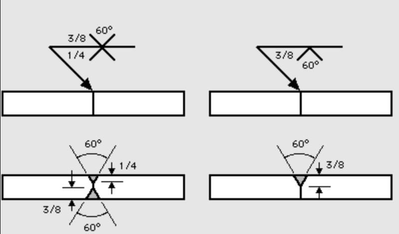
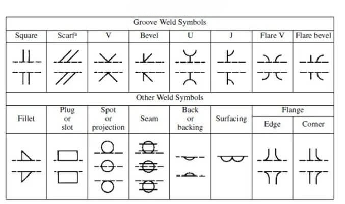
Weld Symbols
A missing root opening or groove angle on a drawing forces the fabrication team to guess. Ambiguous weld symbols lead to inconsistent edge preparation across different production batches.
Drawings must explicitly state the groove angle, root face, and root opening using standard AWS or ISO symbols. Clear callouts prevent communication breakdowns between the engineering department and the welding bay.
Penetration Requirements
If a joint requires complete fusion, the drawing must clearly indicate CJP. Leaving penetration depth up to the welder’s discretion is a major quality risk for structural components.
For PJP joints, specify the exact required depth of penetration. This allows the fabrication shop to select the most cost-effective bevel depth and welding process to meet the requirement.
Visual Inspection
Quality control starts before the arc is struck. Visual inspection (VT) of the fit-up is critical to ensure the root gap and root face meet the specified tolerances.
If the fit-up is inconsistent, the welder will struggle to control the root pass, risking burn-through or lack of fusion. Inspecting the bevel preparation catches machining errors before they become expensive welding defects.
Ultrasonic and Radiographic Testing
Joints subjected to Ultrasonic Testing (UT) or Radiographic Testing (RT) under AWS or ASME codes require flawless edge preparation.
Variations in the bevel angle or an inconsistent root face lead to incomplete fusion. On an X-ray film, this immediately registers as a straight dark line, resulting in a failed inspection.
Furthermore, overly steep side walls in the bevel can cause false reflections during UT, complicating the inspector’s job. The bevel design must physically accommodate the specific non-destructive testing methods required for final QA acceptance.
Conclusion
Bevel design directly controls the cost, strength, and manufacturability of heavy welded assemblies. Specifying the right joint geometry keeps filler metal consumption down, minimizes distortion, and prevents expensive back-gouging and rework.
If you need to optimize your sheet metal or heavy plate fabrication, send your drawings to Shengen. Our engineering team provides practical Design for Manufacturing (DFM) reviews to balance joint strength with mass-production efficiency.
FAQs
At what thickness is a bevel weld strictly required?
A bevel is generally required when welding steel plates thicker than 6mm (1/4 inch). Below this thickness, standard welding processes can achieve full penetration on a square butt joint.
Can I use a laser or plasma cutter to make a J-groove?
No. J-grooves and U-grooves require a specific curved profile that cannot be created with thermal cutting. They must be machined using CNC mills, edge planers, or specialized mechanical beveling tools.
What is the difference between a bevel and a chamfer?
While they look similar, their engineering purposes differ. A bevel is machined specifically to allow welding electrode access and ensure joint penetration. A chamfer is typically used to break sharp edges for safety, aesthetics, or mechanical clearance.
Does a wider bevel angle prevent burn-through?
No. A wider angle actually increases the risk of burn-through if the root face (the flat land at the bottom) is too thin. Controlling the root face dimension and the root gap is the proper way to manage bottom-pass blowouts.
Does beveling Q235 carbon steel differ from 304/316 stainless steel?
Yes. Q235 carbon steel is forgiving and easy to machine. Stainless steel grades like 304 and 316 tend to work-harden during mechanical beveling and warp heavily during welding. For stainless, keeping the bevel volume as small as structurally permissible is critical to restrict heat input and prevent distortion.
Hey, I'm Kevin Lee

For the past 10 years, I’ve been immersed in various forms of sheet metal fabrication, sharing cool insights here from my experiences across diverse workshops.
Get in touch
Kevin Lee
I have over ten years of professional experience in sheet metal fabrication, specializing in laser cutting, bending, welding, and surface treatment techniques. As the Technical Director at Shengen, I am committed to solving complex manufacturing challenges and driving innovation and quality in each project.


