Many sheet metal enclosures fail the transition from 3D CAD to the shop floor. While a design might look flawless on screen, ignoring standard press brake limits, tooling clearances, and material tolerances guarantees production delays and immediate cost overruns.
With over a decade of experience moving projects from rapid prototyping to mass production, our engineering team consistently sees the same pattern: parts that function well as single prototypes often require structural redesigns before they can be manufactured efficiently at scale.
This guide cuts out the theory. It outlines the exact Design for Manufacturing (DFM) rules—from bend radii formulas to hardware integration—needed to engineer enclosures that are structurally sound, easy to assemble, and highly cost-effective to produce.
Requirements That Prevent the Wrong Enclosure From Being Designed
Before opening a CAD program, the fundamental constraints of the project must be established. Skipping this phase often leads to over-engineered parts or enclosures that fail in their actual application.
Match Material Choice to the Operating Environment
The environment where the enclosure will operate dictates material selection and surface finishing. For indoor, temperature-controlled settings, cold-rolled steel treated with a standard powder coat is usually sufficient and cost-effective.
If the unit will be exposed to high humidity, marine environments, or corrosive chemicals, specifying 5052 aluminum or 304/316 stainless steel prevents premature structural failure and rust.
Maintain 5-10mm Clearances for Internal Layouts
The physical dimensions of the enclosure depend entirely on the components housed inside. Begin the design process by mapping out the largest internal parts, such as power supplies, printed circuit boards (PCBs), and transformers.
It is standard practice to leave a minimum clearance of 5mm to 10mm between live electrical components and the metal walls. This helps prevent electrical shorting and establishes the baseline internal volume required.
Ensure Physical Clearance for Assembly Tools
Assembly technicians and maintenance personnel need adequate space to work. Designs must account for the physical dimensions of the tools—such as screwdrivers, rivet guns, or torque wrenches—required to secure internal hardware.
A common DFM error is placing mounting standoffs too close to an internal bent flange. This often requires special right-angle screwdrivers or causes the fastener to interfere with the bend radius. A safe engineering rule is to leave at least [Tool Diameter + 5mm] of clearance from any inside bend.
Define IP Ratings Early to Guide Seam and Joint Design
Ingress Protection (IP) or NEMA ratings directly influence how the enclosure joints must be designed. Standard spot welding or intermittent seam designs are usually used for IP20 to IP40 ratings, where basic dust and minor debris are the primary environmental concerns.
Achieving an IP65 rating or higher generally requires continuous seam welding and the integration of compressed sealing gaskets. These requirements change the flat pattern design and significantly increase post-welding grinding time.
Use Volume Targets to Determine Fabrication Methods
Material volume, press brake setup times, and assembly methods drive the final price per unit. A complex enclosure heavily reliant on manual welding might be acceptable for a low-volume rapid prototype.
However, as volumes scale, manufacturing methods must adapt. For runs under 500 units, laser-cut tab-and-slot designs with manual welding are often cost-effective. As volumes scale past 1,000 units, redesigning for stamped U-shapes and PEM fasteners significantly lowers the per-unit labor cost.
Structure Choices That Reduce Bending, Welding, and Tolerance Risk
The foundational geometry of the enclosure determines how easily it moves through the laser cutting and bending stages. Selecting standard structural approaches minimizes material waste and reduces the risk of dimensional errors.
Prioritize U-Shaped Bases to Minimize Scrap and Setup
U-shaped bases are highly common in the manufacturing industry because they are structurally rigid and simple to process. Formed from a single flat pattern with two primary bends, this shape requires minimal setup time on the press brake.
It works well for rack-mounted equipment, industrial control boxes, and standard desktop units, while keeping scrap material to a minimum.
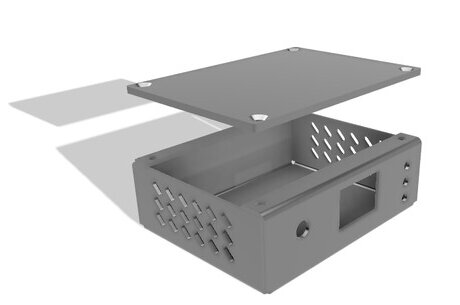
Use L-Shaped Covers for Easier Internal Access
L-shaped panels are frequently used in combination with U-shaped bases to complete a two-piece enclosure. This configuration allows operators full access to the internal components from two different angles during final assembly.
Because they only require a single 90-degree bend, L-shapes maintain high dimensional accuracy and are highly efficient to produce at scale.
Implement Tab-and-Slot Joints to Eliminate Custom Welding Fixtures
When sheet metal parts must be welded or permanently joined, tab-and-slot designs help align the components automatically. This self-fixturing approach reduces the need for expensive, custom welding jigs.
It also minimizes manual alignment errors during assembly. It is an effective structural choice that maintains tight tolerances from the first prototype through full production runs.
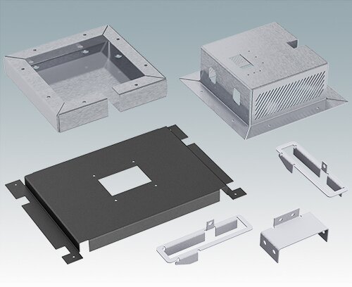
Split Complex Geometries to Improve Material Utilization
A single complex flat pattern with multiple bends reduces the total number of separate parts, but it increases the risk of folding collisions on the press brake. It can also be highly inefficient to cut.
A complex one-piece flat pattern might leave 40% of the sheet metal as scrap. Splitting it into two L-shaped parts can improve material utilization by nesting them efficiently on the laser cutter bed. Multi-part designs rely on screws and rivets, which may slightly increase assembly time but reliably lower the total material cost.
Design Oversized Holes to Absorb Tolerance Stack-Up
Standard sheet metal bending tolerances typically range from ±0.2mm to ±0.5mm depending on material thickness. When multiple folded parts are bolted together, these minor dimensional variations compound.
Designing slightly oversized mounting holes or using slotted cutouts for mating components absorbs these variations. This prevents alignment failures during the final assembly stage and reduces rework on the shop floor.
DFM Details That Make Cutting and Bending Easier
Translating a 3D model into a physical part requires flattening the geometry and physically pressing it into shape. Small oversights in CAD often translate into significant tooling challenges on the shop floor. Standardizing specific design features reduces machine setup time and prevents material defects.
Maintain a Consistent Bend Radius to Eliminate Setup Delays
Every time a bend radius changes in a design, press brake operators must stop the machine and swap out the physical tooling. In a standard factory environment, a single punch and die changeover typically takes 15 to 30 minutes.
If a single enclosure requires three different bend radii, the machine downtime alone will drastically inflate the per-unit cost, especially for low-volume orders. A standard industrial practice is using a single bend radius equal to the material thickness (1T) for the entire part.
Ensure Flange Heights Exceed Minimum Press Brake Limits
Flanges must be long enough to rest securely on the bottom V-die during the bending process. If a flange is too short, the material will slip into the die, causing distorted bends or heavy tooling marks.
A reliable engineering guideline is designing flanges to be at least four times the material thickness, plus the bend radius (4T + R). If a shorter flange is strictly necessary, it may require custom tooling or post-bend machining, which increases the unit price.
Position Holes Outside the Bending Deformation Zone
When sheet metal is bent, the material stretches on the outside of the radius and compresses on the inside. Holes or cutouts placed too close to a bend line will distort into ovals during this deformation.
To prevent this, the standard engineering formula is placing the edge of any hole at least 2.5 times the material thickness, plus the bend radius (2.5T + R), away from the bend line. This ensures hardware will fit properly without requiring manual filing on the assembly bench.
Add Bend Reliefs to Prevent Material Tearing
When bending a flange that does not extend the full length of a sheet edge, the material at the adjacent corners will tear due to localized stress. Bend reliefs are small cutouts placed at these stress points to allow the metal to fold cleanly.
These reliefs should typically be wider than the material thickness and deeper than the bend radius. Skipping this detail often results in micro-cracks that compromise the structural integrity of the enclosure over time.
Provide Clean Flat Patterns to Prevent Engineering Holds
While 3D models are essential for design validation, the shop floor runs on 2D flat patterns. Sending files with unmerged lines or missing bend deductions slows down machine programming.
More importantly, if the flat pattern is calculated using an incorrect K-factor, the final bent dimensions will be out of tolerance. Professional contract manufacturers will typically flag this and place the project on an “Engineering Hold.” This back-and-forth communication to verify the correct dimensions usually wastes one to two days of production time.
Plan Hardware and Access Before Assembly
An enclosure is only as good as its final assembly. Specifying the wrong fasteners or ignoring tool clearances can turn a straightforward production run into a labor-intensive bottleneck. Planning the hardware integration early keeps the assembly line moving predictably.
Use PEM Fasteners but Maintain Safe Edge Clearances
Tapping threads directly into sheet metal thinner than 1.5mm often results in stripping under standard torque loads. Self-clinching fasteners, such as PEM nuts and studs, provide strong, reusable load-bearing threads.
However, because these fasteners require high pressure to displace the metal, placing them too close to the part edge is a common DFM failure. The displaced metal will push outward, causing noticeable edge bulging and dimensional inaccuracy. Always verify the manufacturer’s specified minimum centerline-to-edge distance before finalizing hole placements.
Specify Blind Standoffs for a Clean and Sealed Exterior
When internal components require mounting points but the exterior of the enclosure must remain visually flush, blind standoffs are usually used. They are pressed into the inside face of the metal without penetrating the outer surface.
This approach maintains a smooth, professional appearance on the outside. Because there is no through-hole, it also eliminates potential dust or moisture entry points, making it highly beneficial for achieving specific IP ratings.
Verify Physical Clearance for Automated Assembly Tools
Even if a fastener fits perfectly in the CAD assembly, technicians must be able to physically reach it on the bench. Placing hardware in tight internal corners forces the use of manual hand tools, which measurably increases labor time.
Always leave adequate vertical and horizontal clearance for standard pneumatic rivet guns or battery-powered torque drivers. Designing for automated tool access is critical when transitioning from prototype to volume manufacturing.
Isolate PCB Mounting Points to Prevent Solder Pad Tearing
Printed circuit boards are highly rigid. During shipping or drop tests, large sheet metal panels undergo minor deformation and rebound.
If a PCB is rigidly mounted across a large, unreinforced sheet metal span, this rebound force will transfer directly into the board, often tearing the solder pads off the surface-mount components. To prevent this, use dedicated internal brackets or localize the PCB standoffs near structural corners where the metal is stiffest.
Design Dedicated Tie-Down Points for Cable Routing
Loose internal cables are prone to pinching when the enclosure cover is finally secured. Instead of relying on adhesive cable tie mounts—which frequently fail due to thermal cycling and time—design permanent solutions directly into the sheet metal.
Punched loops or dedicated sheet metal tie-down bridges provide a permanent routing path. This keeps wire harnesses safely away from sharp edges, moving parts, or heat-generating components for the lifespan of the equipment.
Build in Heat Control, Sealing, EMI, and Finish Requirements
Advanced enclosure design goes beyond basic geometry. When equipment is deployed in the field, it must manage internal heat, block electromagnetic interference, and withstand environmental exposure. Failing to design for these physical realities often requires costly aftermarket modifications.
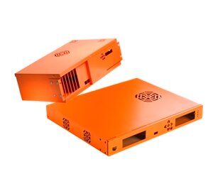
Use Directional Louvers and Standoffs for Passive Heat Control
High-power internal components generate heat that must escape to prevent equipment failure. Instead of relying on simple punched holes, directional louvers are often used to guide natural convection currents and pull cooler air from the bottom of the enclosure.
Always orient stamped louvers facing downward on vertical panels. This allows hot air to escape while acting as a physical shield against falling dust and fluid ingress, helping maintain basic IP ratings. When active cooling fans are not an option, mounting heat-generating components directly to the chassis using thermal pads efficiently dissipates heat across the large metal surface area.
Control Gasket Compression to Achieve Reliable IP Ratings
Achieving an IP65 or higher rating requires continuous seals, usually made from rubber, silicone, or foam-in-place gaskets. However, simply squeezing a flat gasket between two sheet metal panels often pushes the material out of place over time.
To prevent over-compression, design a folded sheet metal hem or utilize a specific standoff height that acts as a physical stop. This ensures the gasket is compressed only to the manufacturer’s specification—typically 20% to 30%—maintaining a watertight seal without degrading the rubber.
Design Overlapping Seams and Masking for EMI Shielding
Electronic devices must often pass strict Electromagnetic Interference (EMI) or Radio Frequency Interference (RFI) testing. A common design failure is applying a non-conductive powder coat over the entire enclosure, which breaks the electrical continuity between mating parts.
To create an effective Faraday cage, design overlapping seams and specify clear masking areas on the manufacturing drawing. Keep masked areas simple and straight. Applying high-temperature masking tape is a manual process; complex masking geometries significantly slow down the finishing line and increase labor costs.
Limit Continuous Welding to Prevent Thermal Distortion
Specifying continuous seam welds along every joint adds significant structural strength but introduces massive heat into the part. In thin sheet metal (under 2mm), this concentrated heat causes severe warping and dimensional distortion that is difficult to correct.
Straightening heat-warped thin metal requires manual hammering or flame straightening, which introduces unscalable labor costs and leaves visible surface defects. Unless a hermetic seal is required for an IP rating, stitch welding (intermittent welding) or spot welding is usually sufficient. These methods reduce heat input and keep manufacturing costs under control.
Match Surface Finishes to Material and Tolerance Requirements
Surface finishes protect the metal but also change the final physical dimensions of the part. Powder coating typically adds 0.05mm to 0.15mm of thickness per surface, which can cause severe tolerance issues if internal clearances or sliding rails are tight.
Always explicitly communicate critical dimensions as “post-plating” or “post-painting” on the engineering drawing. For cold-rolled steel, powder coating or zinc plating is necessary to prevent rust. Aluminum enclosures are often anodized, which hardens the surface without adding significant thickness.
Conclusion
Effective sheet metal enclosure design is not just about fitting components inside a box; it is about making that box manufacturable, repeatable, and cost-effective. By applying these DFM principles early, engineers can reduce scrap rates on the press brake, eliminate manual bottlenecks during assembly, and lower the final unit price.
If you are finalizing an enclosure design and need a manufacturability review, our engineering team at Shengen can help. With over 10 years of experience in sheet metal fabrication, we support projects from rapid prototyping through to mass production. We ensure your parts transition smoothly from CAD to the shop floor with reliable quality and efficient production times.
FAQs
What is the best sheet metal material for outdoor enclosures?
For outdoor or corrosive environments, 5052 aluminum or 304/316 stainless steel are the standard choices. Aluminum is lighter, easier to machine, and naturally corrosion-resistant. Stainless steel provides higher impact strength and rigidity for harsh industrial environments but is more difficult to cut and bend, which increases fabrication costs.
How thick should the sheet metal be for a general industrial enclosure?
Most general industrial and commercial enclosures use material between 1.2mm and 2.0mm (18 gauge to 14 gauge). This thickness range offers a highly practical balance. It provides enough structural rigidity to protect internal components while remaining thin enough to be easily processed on standard laser cutters and press brakes.
Why are the mounting holes on my flat pattern stretching after bending?
The holes are likely located too close to the bend line and are falling inside the deformation zone. When metal is folded, the material stretches on the outside radius. To prevent hole distortion, ensure the edge of any hole is at least 2.5 times the material thickness, plus the bend radius, away from the bend line.
At what volume does it make sense to move from laser cutting to hard tooling (stamping)?
For volumes under 5,000 units, laser cutting and CNC press brakes remain the most cost-effective approach due to zero tooling costs. As annual volumes exceed 10,000 units, investing in custom sheet metal stamping dies makes sense. The drastic reduction in per-unit cycle time at that scale easily outweighs the initial tooling investment.
Hey, I'm Kevin Lee

For the past 10 years, I’ve been immersed in various forms of sheet metal fabrication, sharing cool insights here from my experiences across diverse workshops.
Get in touch
Kevin Lee
I have over ten years of professional experience in sheet metal fabrication, specializing in laser cutting, bending, welding, and surface treatment techniques. As the Technical Director at Shengen, I am committed to solving complex manufacturing challenges and driving innovation and quality in each project.


