Modern products often need sheet metal parts with precise bends. Sometimes, the wrong bend can make assembly tough. Many engineers and managers face challenges when choosing the proper bending method. This post will guide you through the basics, practical tips, and popular types, enabling you to make informed decisions and avoid common mistakes.
Sheet metal bending is the key to turning flat metal into functional parts. When you understand the methods and best practices, you can select better parts and make more informed choices. Ready to learn the basics and the details? Keep reading.
What Is Sheet Metal Bending?
Sheet metal bending is the process of applying force to a metal sheet to make it bend at a certain angle. The material stays in one piece but changes shape. Tools like a punch and die in a press brake are commonly used. The sheet bends when the punch pushes it into the die. The final shape depends on the tool geometry, the force applied, and the material type.
This process can create simple angles or complex forms. Common bends include V-bends, U-bends, and channels. Bending can be done in one step or multiple passes. The method chosen affects bend accuracy, springback, and production speed.
Common Bending Methods
Each bending method is most effective under specific conditions. The right choice depends on part design, material type, and production needs.
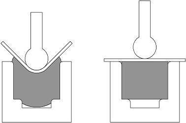
Air Bending
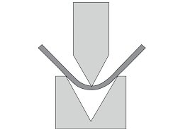
Air bending is the most common method of bending. It uses a punch to press the metal into a V-shaped die, but the punch does not touch the bottom. The sheet bends by touching only the edges of the die and the tip of the punch.
This method allows for flexible bend angles using the same tools. It uses less force than other methods. However, it has more springback, so accuracy depends on machine control and operator skill.
Bottoming
Bottoming, also known as bottom bending, fully presses the sheet into the die. The punch touches the material until it sits at the bottom of the V. This gives better accuracy and less springback compared to air bending.
It requires more force and specific punch-die sets for each angle. This method is ideal when high precision and repeatability are needed in larger runs.

Coining
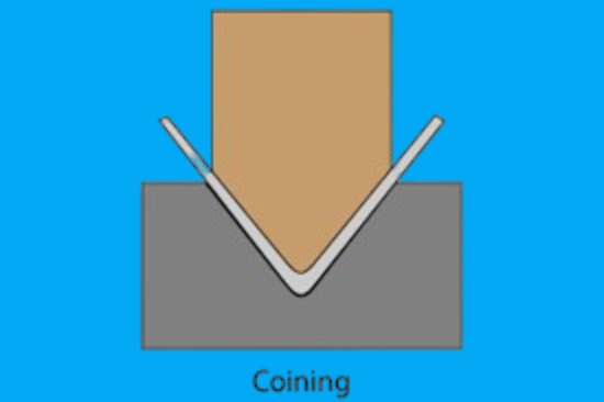
Coining uses very high pressure to press the punch deep into the material. This flattens the contact area and thins the metal slightly at the bend. The result is a sharp bend with almost zero springback.
Coining gives the highest accuracy but puts stress on tools and machines. It works best for very small or detailed parts that require tight tolerances.
Rotary Bending
Rotary bending uses a rotating die to form the bend as the punch moves down. The rotating motion reduces friction and marks on the metal. This method is often used for bending tubes or coated materials where surface quality matters.
It’s also helpful in forming 90° bends without springback. Rotary bending can bend past 90° without damaging the part surface.

Roll Bending
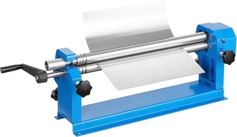
Roll bending utilizes three rollers to bend the sheet into a curve gradually. The sheet passes through the rollers, which apply pressure over a longer area. This method is used to produce cylinders or parts with large radii.
Roll bending is slower and less precise for tight angles. But it works well for large parts or continuous curves in thick materials.
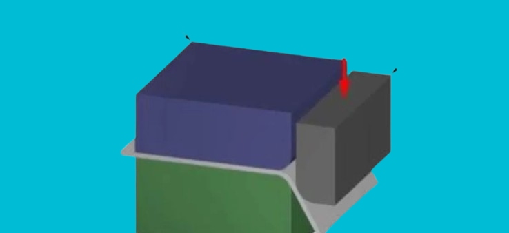
Wipe Bending
Wipe bending utilizes a pressure pad to secure the sheet in position. A punch then pushes the free edge down alongside a straight wipe die. This method is often used for creating flanges on the edge of a part.
Wipe bending is fast and straightforward. However, it can leave marks on the material and may require extra care to control the bend angle and spring back.
V-Bending
V-bending forms the sheet by pressing it into a V-shaped die with a punch. This can be done as air bending or bottoming, depending on how deep the punch goes.
It is the most widely used bending form. It’s flexible and works for many angles and part types. The angle depends on punch depth and material springback.

U-Bending
U-bending creates a U-shaped channel using a punch and die. It bends the sheet twice in one step. This method is helpful for channels, enclosures, and support brackets.
It requires careful tool design to control part shape and avoid deformation. U-bending usually involves more springback than V-bending.
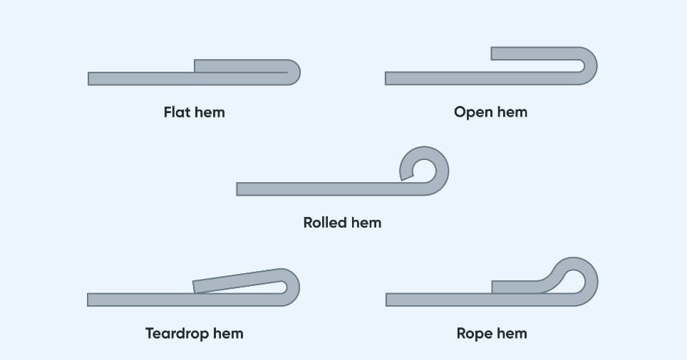
Hemming
Hemming folds the sheet edge over itself. It’s used to strengthen edges, remove sharp corners, or create a clean finish. Hemming has two stages: first, a bend, then a flattening step.
This method is standard in enclosures, covers, or parts where the edge appearance is essential. It needs tight control to avoid cracking or uneven folds.
Factors Influencing the Bending Process
Several factors influence how metal bends and the accuracy of the final part. Knowing these can help improve part quality and avoid bending errors.
Bend Allowance
Bend allowance is the length of material needed to make a bend. When metal bends, it stretches slightly on the outer side and compresses on the inner side. Bend allowance helps account for this.
Bend Allowance Formula:
BA = A × (π/180) × (R + K × T)
Where:
- A = Bend angle (in degrees)
- R = Inside bend radius
- T = Material thickness
- K = K-Factor (typically between 0.3–0.5 for most materials)
This formula helps you calculate how much longer the flat sheet should be before bending.
Bend Radius and Angle
The bend radius is the inside radius of the bend. A larger radius results in less stress and less chance of cracking. Sharp bends in thick or rigid materials may lead to part failure.
- A typical rule: The bend radius should be at least equal to the material thickness for most metals.
- The bend angle is the total angle formed after bending. For example, a 90° angle forms a right-angle bend.
K-Factor
The K-Factor is the ratio between the location of the neutral axis and the material thickness. It affects bend allowance and helps define how much material stretches.
K = t / T
Where:
- t = Distance from the inside face to the neutral axis
- T = Total material thickness
Common K-Factor values:
- Soft aluminum: 0.33
- Mild steel: 0.42
- Stainless steel: 0.45
You can adjust the K-Factor based on material type, thickness, and bend method.
Springback Effect
After bending, the metal tends to “spring back” slightly toward its original shape. This is due to the elastic recovery of the material. If not accounted for, the bend angle will be off.
To deal with springback:
- Overbend slightly beyond the target angle
- Use bottoming or coining to reduce the effect
Example:
If aiming for a 90° bend in stainless steel, the press might need to form an 88° angle to achieve the correct result after springback.

Sheet Metal Bending Design Tips
A well-designed product can reduce production issues, prevent material failure, and enhance the final fit. The tips below help create cleaner, stronger, and more cost-effective bends.
Best Practices for Hole and Slot Placement
Avoid placing holes or slots too close to the bend line. During bending, these features can become distorted or torn.
General rule: Keep holes at least 2× material thickness (T) away from the bent edge.
Example: For 1.5 mm thick steel, holes should be no closer than 3 mm from the bend line.
If the hole must be closer, consider pre-bending the part before punching or adding reinforcement to prevent distortion.
Minimum Flange Length Guidelines
The flange is the flat area that extends from the bend. If it’s too short, the die or punch might damage the part.
Minimum flange length formula (air bending):
Min Flange = V × 0.5
Where:
- V = Die opening width (usually ~8×T for standard tools)
Example: For a 2 mm sheet with a V-die opening of 16 mm:
Min Flange = 16 × 0.5 = 8 mm
If the flange is shorter than this, you may need custom tooling or a different bending sequence.
Chamfered Sides
Sharp corners near bends can cause tears or wrinkles. Chamfering the edge removes excess material and lowers stress.
Tip: Chamfer or round-off corners that will be near the end zone, especially on thicker parts or high-strength materials.
Even a 45° chamfer can prevent cracking and improve appearance.
Hole Distance from Bend
A second rule for hole distance:
If the hole is on the inside face of a bend, place it at least:
Distance = Radius + 1.5 × T
If it’s on the outside face, use:
Distance = Radius + 3 × T
This avoids deformation as the metal stretches or compresses.
Bend Relief
Bend relief is a notch or slot at the bend line to prevent tearing and distortion. It allows the material to move freely during bending.
Design suggestion:
- Relief width ≥ material thickness
- Relief depth ≥ bend radius + 1.5 × T
Use bend relief when two bends are close or when a flange wraps around another face.
Check the Flat Pattern
Before bending, always review the flat pattern in CAD. Ensure the flat layout includes accurate bend allowances, the correct K-factor, and proper feature placement.
Use bend tables in CAD to automate this step and reduce errors. Export the flat layout with the correct unfolding for laser cutting or punching.
The Bending Line is Parallel to a Side
Make sure at least one bend line is parallel to one side of the sheet. This improves alignment during setup and simplifies the use of fixtures.
Avoid complex angles unless necessary. Straight, parallel bends are faster and more accurate.
Conclusion
Sheet metal bending turns flat sheets into functional 3D parts. The process involves various methods, including air bending, bottoming, and coining—each with its advantages and disadvantages. Key factors, such as bend allowance, radius, K-factor, and springback, directly affect accuracy. Using the correct method and design together improves part quality and reduces production time.
Need help with your sheet metal bending project? Tell us what you’re working on, and our engineering team will provide fast feedback, DFM suggestions, and accurate quotes—all within 24 hours.
Hey, I'm Kevin Lee

For the past 10 years, I’ve been immersed in various forms of sheet metal fabrication, sharing cool insights here from my experiences across diverse workshops.
Get in touch
Kevin Lee
I have over ten years of professional experience in sheet metal fabrication, specializing in laser cutting, bending, welding, and surface treatment techniques. As the Technical Director at Shengen, I am committed to solving complex manufacturing challenges and driving innovation and quality in each project.


