A sheet metal flange is a bent edge formed on a workpiece to increase structural rigidity, provide an assembly mounting surface, or enclose a profile. Reliable flange design requires specific minimum height formulas (like 4t+R) and bend reliefs to prevent material tearing and press brake tooling collisions.
While designing a flange in CAD is as simple as clicking an edge, manufacturing it is strictly bound by the physical limits of the press brake. A flange that ignores these limits can easily cause a 20% scrap rate on the shop floor. When forming constraints are skipped during the drawing stage, short flanges slip out of the V-die, tapped holes near the bend line distort, and angle variations destroy assembly tolerances.
To prevent these delays and reduce custom tooling costs, this guide breaks down the essential Design for Manufacturability (DFM) rules for straight flanges. You will learn:
- How to calculate the true minimum flange height based on your material.
- The required hole-to-bend clearances to prevent feature distortion.
- How return flanges and bend sequences impact tooling interference.
- Cost-reduction strategies for flange tolerances and flat patterns.
(Note: This article focuses on straight flanges formed on a press brake. Hole flanging and stretch/shrink flanges are evaluated in our dedicated stamping guidelines.)
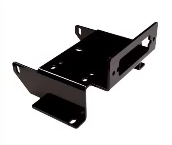
Understand the Flange Before Choosing Its Shape
Before setting dimensions, clarify what the flange needs to do and how its cross-section supports that function. This determines whether you need a high-precision bend or a simple edge fold.
Flange Geometry and Dimensions
A standard flange consists of the flange face, the free edge, the inside bend radius, and the bend tangent lines. It is critical to distinguish the finished flange height from the straight flat length. The straight length only measures the flat section after the bend radius, while the finished height measures from the opposite face to the free edge. Using a simple L-shaped cross-section establishes these basic reference points for manufacturing.
Stiffening and Connection Requirements
Adding a flange significantly increases the bending stiffness of a flat sheet along that axis. Beyond rigidity, flanges provide mounting surfaces for hardware, locating tabs for assembly, or overlapping areas for spot welding.
If the flange is used for sealing, the design must account for a continuous contact surface and closed corners. This requires tight tolerances. In contrast, an edge bend intended only for deburring or protecting internal wire routing requires less precision and can tolerate wider angle variations.
Straight, Return, Offset, and Hemmed Edges
Different flange profiles require different tool setups and directly impact unit costs:
- Straight Flanges (90°): The most common edge. Processed with standard punch and die setups. Cost impact: Lowest.
- Return Flanges (U-Shape): Used for covers and tracks. These require sufficient clearance between the bends. If the gap is too narrow, standard gooseneck punches will not fit, forcing the shop to buy custom tooling. Cost impact: Medium to High.
- Offset Flanges (Joggles): Step bends used to create a flush surface when overlapping two sheets. These require specialized offset dies or two separate hits on the press brake. Cost impact: Medium.
- Hemmed Edges: Folded completely flat (or teardrop-shaped) to create a safe edge or double the material thickness. Hems require highly ductile materials and a two-stage flattening die. Cost impact: Medium.
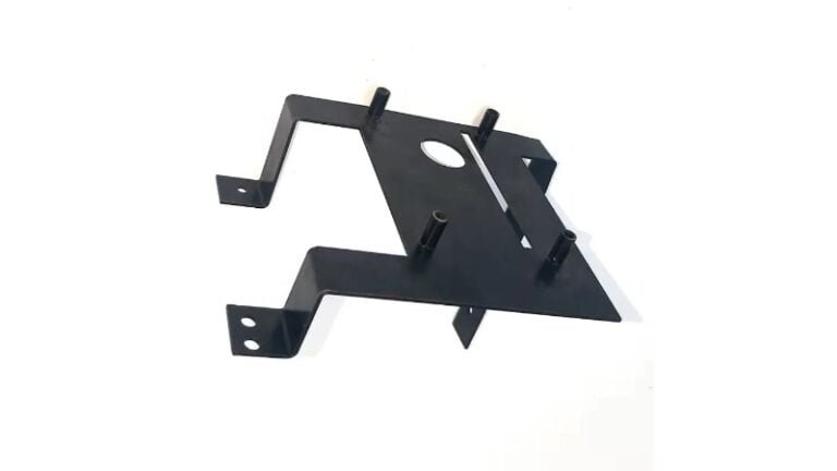
Set Flange Height and Bend Radius
Once the shape is determined, check the dimensions against the physical realities of the material and the press brake V-die.
Finished Height and Straight Length
Clear dimensioning prevents misinterpretation. Always specify whether you are measuring the outer overall height (OD) or the inner dimension (ID). Outer dimensions are generally preferred because they dictate how the part fits within an assembly. Specify the finished OD height on your drawing; the manufacturer will calculate the flat pattern length based on their specific bend deductions.
Minimum Height and Die Opening
During air bending, the sheet metal must rest securely across the two shoulders of the V-die. If the flange is too short, the material gets dragged into the V-die opening (a defect known as die roll). This creates a flared edge, ruins the cosmetic surface, and results in an inaccurate bend angle.
As a preliminary screening rule, the minimum flange height should be 4 times the material thickness plus the inside bend radius (4t + R).
Shop Floor Note: At Shengen, the #1 reason we have to request a design change or DFM waiver is a flange height that is shorter than standard V-die openings can support. While a 5mm flange on 2mm steel works in CAD, a standard 12mm V-die requires at least an 8.5mm flange height to properly support the material without slipping.
Flanges that push below these limits require test bends or expensive custom wiping dies, increasing setup time and cost.
Material and Bend Radius
Forming behavior varies drastically by alloy and temper. Bending parallel to the material’s grain direction increases the risk of cracking.
For example, while 5052-H32 aluminum can often be bent to a tight 1t radius without issue, applying the same radius to 6061-T6 aluminum—especially parallel to the grain—will almost guarantee micro-cracking at the bend line. The quality of the cut edge (laser vs. punched) also affects where stress fractures initiate.
Furthermore, the punch tip radius is not always the exact formed inside radius of the part. In air bending, the material naturally forms a radius relative to the V-die opening. Whenever possible, rely on the standard tooling combinations confirmed by your manufacturing supplier rather than forcing a theoretical CAD radiu
Furthermore, the punch tip radius is not always the exact formed inside radius of the part. In air bending, the material naturally forms a radius relative to the V-die opening. Whenever possible, rely on the standard tooling combinations confirmed by your manufacturing supplier rather than forcing a theoretical CAD radius that requires a custom punch.
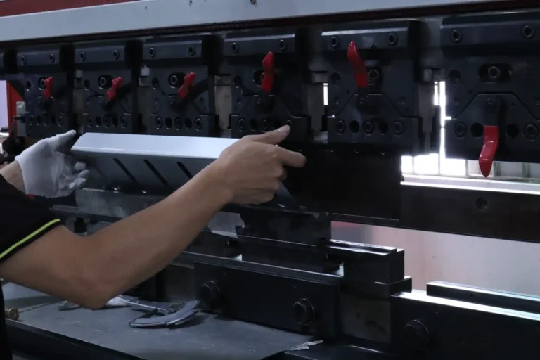
Check Features, Assembly Space, and Bend Access
Flanges do not exist in isolation. Once the basic flange dimensions pass the physical limits of the V-die, you must evaluate how the flange interacts with surrounding features, hardware, and the press brake tooling itself.
Hole Clearance and Bend Relief
When holes, slots, or cutouts are placed too close to the bend line, the natural stretching of the material pulls them into an oval shape. A standard guideline is to keep the edge of any hole at least 2.5 to 3 times the material thickness (2.5t – 3t) away from the bend tangent line.
While a distorted clearance hole might just be a cosmetic issue, a distorted tapped hole or a squeezed PEM nut hole means the hardware will not install, scrapping the entire part. Always prioritize keeping hardware insertion points well outside the deformation zone.
If you are bending a partial flange along an edge, you must add bend reliefs to prevent the adjacent flat material from tearing. A standard bend relief should be at least as wide as the material thickness (1t) and cut deeper than the bend radius plus the material thickness (R + t).
Fastener and Welding Access
Flange design must account for the physical tools used in the next assembly step. Check the clearance for screw heads, washers, sockets, and the installation dies required for hardware insertion.
For spot-welded assemblies, the flange must provide enough surface area for the welding electrodes to make full flat contact.
Shop Floor Note: At Shengen, we generally recommend a minimum flange width of 12mm to 15mm for spot welding. Narrower flanges risk poor weld penetration or require the operator to angle the electrode tips, which weakens the joint and damages the equipment.
Bend Sequence and Tool Interference
A press brake forms one bend at a time. As successive bends are made, the part pivots and wraps around the tooling. Return flanges (U-shapes) and deep boxes are especially prone to colliding with the punch, the machine ram, or the backgauge during the forming cycle.
If the final bend locks the part onto the die, it is unmanufacturable as drawn. If buying custom tooling (like window punches) is not in the budget, a common design-stage fix is to use segmented flanges—cutting the continuous flange into smaller sections to allow standard tooling to bypass the interfering areas.
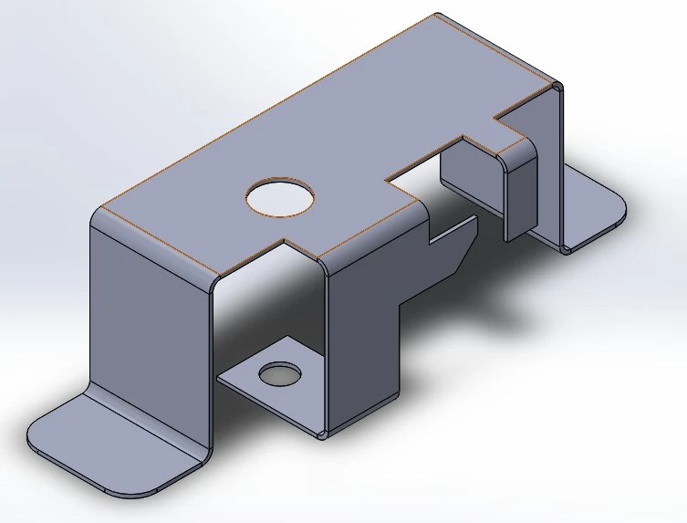
Compare Flange Manufacturing Costs
Design choices dictate whether a part can be processed rapidly on standard equipment or if it requires workarounds that drive up unit costs.
Tooling and Secondary Operations
Standard air bending keeps setup costs low. In contrast, forcing a very short flange or a deep return bend often requires custom wiping dies or specialized gooseneck punches, adding upfront costs and lead time.
| Option[cite: 54] | Cost Factors to Compare[cite: 54] |
|---|---|
| Increase flange height[cite: 54] | Usually free. Simply check if the taller flange interferes with internal assembly space.[cite: 54] |
| Use special tooling[cite: 54] | Adds upfront tooling costs and setup time. Becomes more cost-effective at high volumes.[cite: 54] |
| Form long, then trim[cite: 54] | Requires secondary machining or laser cutting after forming. Drastically increases per-part labor.[cite: 54] |
| Revise the structure[cite: 54] | Splitting the part into two pieces and welding/riveting them shifts cost from forming to assembly.[cite: 54] |
Flat Patterns and Material Utilization
Every additional flange complicates the flat pattern outline. Complex, sprawling flat patterns nest poorly on a standard rectangular sheet of metal. If material utilization drops from 85% to 60% due to an unwieldy flat pattern, the scrap cost is absorbed directly into your unit price. Comparing actual nesting layouts rather than relying on theoretical material yields provides a true picture of material costs.
Tolerances and Order Quantity
Specify tight angle tolerances only where they directly impact assembly functionality. Demanding an angle tolerance of ±0.5° requires the operator to perform manual test bends, adjust for material springback variations, and frequently halt production to check angles.
A standard tolerance of ±1° to ±2° can often be hit directly by modern CNC press brakes without constant manual intervention. Opening up the tolerance on non-critical flanges significantly lowers the per-part cost, especially for short-run or prototype orders.
Inspect Flanges and Resolve Common Defects
Establishing clear inspection criteria prevents disputes between engineering and manufacturing and helps isolate root causes when defects occur.
Dimensional and Surface Inspection
Clearly define whether dimensions are measured in a free state or a constrained (clamped) state. Sheet metal naturally flexes; a long flange that appears slightly out of tolerance when resting on an inspection table may align perfectly once bolted into the assembly.
Additionally, specify if dimensional limits apply before or after plating and powder coating. A standard powder coat adds 50 to 100 microns (2-4 mils) per surface, which can easily consume a tight assembly clearance if not accounted for in the raw sheet metal flat pattern.
Cracking, Distortion, and Angle Variation
When defects surface during prototyping or the first production run, use this baseline to investigate the manufacturing variables:
| Issue[cite: 55] | Checks to Investigate[cite: 55] |
|---|---|
| Bend cracking[cite: 55] | Material temper, punch radius too sharp, grain direction, or poor laser-cut edge quality.[cite: 55] |
| Distorted holes[cite: 55] | Feature is too close to the bend tangent line, or relief cuts are missing/undersized.[cite: 55] |
| Angle variation[cite: 55] | Material batch hardness variation (inconsistent springback), or machine deflection.[cite: 55] |
| Bowed flanges[cite: 55] | Inadequate V-die support, baseline material flatness issues, or unequal stress relief.[cite: 55] |
| Tool marks[cite: 55] | Lack of protective urethane film, dirty dies, or excessive bending tonnage.[cite: 55] |
First-Article and Assembly Verification
Before authorizing a full production run, evaluate the first-article sample using mating parts or check fixtures. Verify that fasteners install cleanly and flanges sit flush against their mating surfaces. Record the verified machine settings, die combinations, and material batches to maintain consistency across the entire order.
Before Releasing Your Drawing
| Check[cite: 56] | Verification[cite: 56] |
|---|---|
| Dimensions[cite: 56] | Are overall heights, inner/outer measurement datums, and radii clearly marked?[cite: 56] |
| Forming[cite: 56] | Is the flange height ≥ 4t + R? Is there clearance for the punch and die?[cite: 56] |
| Features[cite: 56] | Are tapped holes/PEMs safely outside the deformation zone? Are bend reliefs sized correctly?[cite: 56] |
| Assembly[cite: 56] | Is there physical space for wrenches, weld tips, and mating fasteners?[cite: 56] |
| Acceptance[cite: 56] | Are critical assembly tolerances distinguished from standard edge bends?[cite: 56] |
Ready to move from design to production?
A minor flange adjustment today can save thousands of dollars in tooling and scrap tomorrow. Send your CAD files and drawings to the Shengen engineering team for a DFM review. We’ll verify your bend limits, check your clearances, and ensure your parts are optimized for cost-effective manufacturing.
Hey, I'm Kevin Lee

For the past 10 years, I’ve been immersed in various forms of sheet metal fabrication, sharing cool insights here from my experiences across diverse workshops.
Get in touch
Kevin Lee
I have over ten years of professional experience in sheet metal fabrication, specializing in laser cutting, bending, welding, and surface treatment techniques. As the Technical Director at Shengen, I am committed to solving complex manufacturing challenges and driving innovation and quality in each project.