Sheet metal joints are specialized techniques used to connect two or more pieces of sheet metal into structural assemblies. Selection prioritizes material thickness, mechanical load, and production costs. Standard methods range from permanent thermal welding and mechanical fasteners (rivets, bolts) to interlocking configurations like seams and folds.
Beyond strength, these choices dictate welding distortion, assembly speed, fixture complexity, finishing labor, and the potential for automated production. This article breaks down joint geometry and joining methods to help engineering teams control costs and ensure consistent quality from prototype to mass manufacturing.
Choosing the Right Sheet Metal Joint Geometry
The physical configuration of a joint determines how load is distributed across the parts. It also dictates the assembly sequence and the type of fixturing required on the shop floor.
Butt Joints
Butt joints align two sheet edges in the same plane. This configuration works well for parts requiring a flat, continuous surface and fluid-tight sealing, such as tanks or panels.
However, butt joints offer limited surface area for welding and are highly sensitive to fit-up accuracy. Variations in cutting tolerances can lead to gaps that are difficult to fill (typically gaps must be kept under 10% of material thickness). They often require precise laser cutting prior to assembly to maintain production consistency.
Corner Joints
Corner joints connect two sheets at an angle—usually 90 degrees—to form an L-shape. They are the standard approach for constructing machine enclosures, electrical boxes, and protective frames.
The design usually leaves one edge exposed, which requires manual grinding if an aesthetic finish is needed. For exterior panels, manufacturing engineers often prefer closed corner configurations to reduce the time spent on secondary finishing processes and to improve EMI shielding.

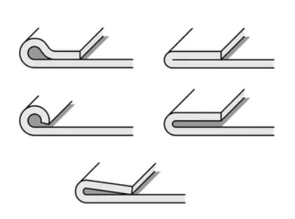
Edge Joints
Edge joints involve placing two parallel sheet edges together. This joint is generally used for reinforcement or to provide a thicker, safer section along the perimeter of a handled part.
While it increases local stiffness, it is less effective at bearing heavy loads compared to other configurations. In production, edge joints are primarily used for non-structural flanges, safety edges, or internal routing channels.

Tee Joints
Tee joints connect the edge of one sheet to the flat surface of another, forming a T-shape. Because the connection is applied along the intersection, it provides high rigidity and is primarily used for internal structural supports, ribs, and mounting brackets.
Managing heat input is the main challenge with this geometry. Welding a thin-gauge sheet (e.g., under 1.5mm) directly to a flat surface frequently causes thermal distortion or visual burn-through on the opposing cosmetic side, requiring careful parameter control or skip-welding techniques.

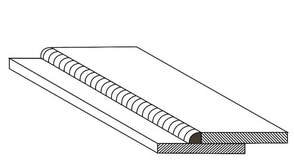
Lap Joints
Lap joints overlap the surfaces of two sheets, providing a large contact area. This design makes the joint highly tolerant to slight variations in part dimensions and cutting tolerances.
Lap joints perform exceptionally well under shear stress and are the required geometry for resistance spot welding and adhesive bonding. Designers should note that the overlap adds a small step in the surface profile and increases material weight, which should be factored into the initial CAD model.
Selecting the Right Sheet Metal Joining Method
The method used to connect the joints impacts the structural yield and the scalability of production. It also determines the extent of post-process finishing required.
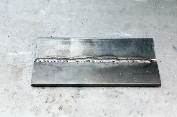
TIG and MIG Welding
TIG welding offers precise control over heat input, making it suitable for thin-gauge stainless steel and aluminum where cosmetic appearance is prioritized. MIG welding operates at faster speeds with higher deposition rates, which becomes more cost-effective at volume for thicker materials like structural carbon steel.
Both methods introduce concentrated heat into the metal. This thermal stress causes warping, requiring dedicated clamping fixtures to maintain dimensional accuracy and, often, post-weld grinding to smooth the joints.
Spot Welding
Resistance spot welding is a fast, highly repeatable process for joining overlapping sheets. It relies on localized pressure and electrical current, introducing significantly less heat into the surrounding material than arc welding.
This method works well for mass production and automated assembly lines. However, it requires specific minimum flange widths to accommodate the welding tips. It is also generally limited to relatively thin materials (typically up to 3mm) and must be performed on bare, unpainted surfaces.
Riveting and PEM Fasteners
Mechanical fastening methods, such as blind rivets and press-in (PEM) hardware, provide reliable joints without any thermal distortion. Because these are cold-forming processes, they do not alter the material’s structural properties or damage pre-applied protective coatings like zinc plating.
While mechanical fasteners add direct BOM (Bill of Materials) costs per unit, they often reduce overall assembly time. They also allow dissimilar metals (like aluminum and steel) to be joined reliably without immediate galvanic corrosion concerns, provided the correct fastener material is specified.
Adhesive Bonding
Industrial structural adhesives distribute stress evenly across the entire joint area, avoiding the localized stress concentration points created by spot welds or rivets. Adhesives are highly effective for joining dissimilar materials and dampening continuous vibration in dynamic environments.
To be effective, adhesives require a lap joint configuration to maximize surface contact. While curing times and strict surface preparation must be factored into the production cycle, bonding is increasingly used for lightweight aluminum structures and achieving a clean exterior finish without the need for post-weld grinding.
Preventing Failures in Production
In sheet metal manufacturing, a joint that looks perfect in a 3D CAD environment may fail on the shop floor. Identifying these risks early allows engineering teams to modify the joint design before committing to costly tooling or large-scale production runs.
Weld Distortion
Heat input from TIG and MIG welding causes localized expansion and contraction, creating a heat-affected zone (HAZ). For thin-gauge sheet metal (typically under 3mm), this thermal stress frequently results in warping, bowing, or buckling of the entire panel.
To mitigate distortion, manufacturers must use heavy clamping fixtures, heat sinks, or implement skip-welding sequences. These interventions require highly skilled labor and add zero functional value to the part. Redesigning the assembly to use mechanical fasteners or spot welding is often the most cost-effective way to eliminate severe thermal deformation.
Fatigue Cracking
In environments subject to continuous vibration or cyclical loading—such as industrial equipment enclosures or automotive brackets—rigid joints can become points of failure. Sharp inside corners and continuous rigid weld beads often act as stress concentrators, leading to micro-cracks over time.
To prevent fatigue failure, engineers usually avoid butt joints in high-stress areas. Utilizing lap joints combined with structural adhesives, or integrating larger bend radii, helps distribute the physical load across a wider surface area, significantly improving the joint’s lifespan without adding material thickness.
Galvanic Corrosion
When dissimilar metals, such as aluminum and carbon steel, are joined in the presence of an electrolyte (like moisture or humidity), an electrochemical reaction occurs. This causes the more anodic metal to corrode rapidly, degrading the joint’s structural integrity.
Preventing galvanic corrosion requires physical isolation between the two materials. In production, this is achieved by applying dielectric coatings, using inert plastic washers, or utilizing specialized transition joints. For outdoor or marine applications, specifying matching materials from the BOM stage is usually the safest engineering choice.
Fit-Up Accuracy
Tolerance stack-up is an unavoidable reality in sheet metal forming. Slight variations from laser cutting (±0.1mm) and press brake bending (±0.2mm to ±0.5mm) mean that joining edges may not align perfectly on the assembly bench.
Joint geometries like tight butt joints are unforgiving and will highlight any dimensional discrepancies. Designing with lap joints or integrating slotted mounting holes provides a physical margin for error, allowing operators to adjust and align the components accurately before the final weld or fastening step.
Designing Sheet Metal Joints for Production
Design for Manufacturability (DFM) is about anticipating the assembly process. A well-designed joint reduces reliance on highly skilled labor, minimizes the need for complex custom fixtures, and standardizes the production cycle.
Welding Access
Engineers sometimes design weld seams deep inside U-channels, acute angles, or enclosed box structures. If a welding torch or spot-welding gun cannot physically reach the joint at the correct angle, the manufacturer cannot execute the weld properly, leading to weak penetration or porosity.
A standard rule in DFM is to maintain a clear line of sight and adequate tool clearance (usually a minimum 45-degree torch angle) around every joint. If access is restricted, the joint must be relocated to the exterior of the assembly, or the joining method should be changed to blind rivets that only require single-sided access.
Tab and Slot Positioning
Relying entirely on external jigs and clamps to hold parts together before welding is expensive and slows down the line. Integrating tabs on the edge of one sheet and corresponding slots on the mating part creates a self-locating joint.
This Poka-Yoke (mistake-proofing) technique ensures parts can only fit together in one specific orientation. It can reduce fixture setup time by up to 50%, allowing entry-level operators to tack-weld complex assemblies with high precision without relying on manual measurement.
Assembly Repeatability
In mass production, relying on manual measurement to position joints leads to inconsistent dimensions from unit to unit. Even small variations in joint placement can cause downstream issues, such as mounting holes not aligning with internal PCBs or mating hardware.
To guarantee repeatability, design mechanical hard stops, alignment notches, or interlocking flanges directly into the sheet metal flat pattern. This built-in geometry ensures that whether a human worker or an automated system is assembling the parts, the placement is identical every time.
Robot-Friendly Layouts
Transitioning from manual assembly to automated welding or robotic spot-welding requires predictable and straightforward joint paths. Robots struggle with complex 3D maneuvering, tight internal corners, and inconsistent gap sizes.
To make a design robot-friendly, standardize the joint types across the assembly and keep weld seams as straight and externally accessible as possible. Minimizing the number of times a part needs to be repositioned or flipped lowers programming time and makes robotic integration highly cost-effective for large volume runs.
Reducing Manufacturing and Finishing Cost
For procurement and project managers, joint design is a primary driver of the final part price. Optimizing joints at the CAD stage is the most effective way to strip hidden costs out of the manufacturing process.
Grinding Reduction
Post-weld grinding and polishing are highly manual, time-consuming processes. When a cosmetic weld is specified on an exposed corner, operators must carefully grind down the bead and blend the finish to match the raw sheet metal. A fully blended and polished cosmetic weld can easily cost 3 to 5 times more in labor than a concealed joint.
To reduce this expense, engineering teams should design enclosures that hide joints on internal or rear-facing surfaces. When cosmetic joints are unavoidable, switching to closed corners or utilizing structural adhesives can completely eliminate the need for secondary grinding, keeping labor costs predictable.
Fixture Complexity
Precision welding requires custom jigs and fixtures to hold parts securely and prevent thermal distortion. The more complex the joint configuration, the more intricate and expensive the clamping system must be. This drives up Non-Recurring Engineering (NRE) costs before a single part is even produced.
Designing self-locating joints, such as tab-and-slot mechanisms, drastically reduces the reliance on heavy tooling. By building the alignment directly into the sheet metal flat pattern, you eliminate expensive custom fixtures and allow the factory to use standard, off-the-shelf clamping setups.
Assembly Time
The time it takes to position, clamp, and join two pieces of metal dictates the throughput of the entire production line. Continuous TIG or MIG welding requires skilled labor and significant time for preparation, execution, and cooling.
If the joint is not subjected to heavy structural loads, replacing continuous welds with spot welding or PEM hardware speeds up the line significantly. Cold fastening methods take seconds per joint and require zero cooling time, lowering the per-unit labor cost and accelerating the overall production schedule.
Automation Compatibility
Scaling a product from pilot runs to mass production usually requires shifting from manual assembly to automated or robotic welding. However, robots require highly predictable, straight paths and cannot easily navigate tight internal corners or compensate for inconsistent gap sizes.
To make a design cost-effective at high volumes, standardize the joint geometries across the entire product. Keeping joints externally accessible and standardizing spot-weld flange widths minimizes robotic programming time and makes automation a financially viable option for the manufacturer.
Joint Selection for Real Applications
Selecting a joint is rarely about finding a universal solution. It requires matching the geometry and joining method to the specific physical challenges and material grades the part will face in its operating environment.
Thin-Gauge Enclosures
Electronic chassis, server racks, and control boxes are typically formed from thin sheet metal (e.g., 0.8mm to 1.5mm galvanized steel or Q235) to save weight and material cost. The primary manufacturing challenge here is that thin materials burn through or warp violently under concentrated heat.
For these applications, continuous arc welding should be minimized. Lap joints combined with resistance spot welding or blind rivets are the standard solutions. They provide adequate strength for static enclosures while keeping the metal cool and structurally sound.
High-Vibration Assemblies
Components used in industrial machinery, automotive brackets, or HVAC mounts are subjected to continuous dynamic loading. In these environments, rigid, continuous welds often become stress concentrators that eventually lead to fatigue cracking.
To handle vibration, the joint must distribute stress over a larger area. Utilizing overlap joints with industrial structural adhesives, often combined with mechanical fasteners, provides a dampening effect. This hybrid joining approach absorbs cyclical stress far better than a standard butt weld.
Cosmetic Stainless Parts
Food processing equipment, medical devices, and high-end consumer appliances often require stainless steel (typically 304 or 316L) with flawless, hygienic surfaces. The challenge is eliminating any crevices, overlapping seams, or exposed fastener heads where dirt or bacteria could accumulate.
In these strict applications, TIG-welded butt joints or fully closed corner joints are required. Although this drives up manufacturing costs due to the necessary back-purging (to prevent oxidation), grinding, and polishing, it is the only way to achieve a seamless, sanitary finish.
Lightweight Aluminum Structures
Aerospace components and electric vehicle (EV) battery enclosures rely heavily on aluminum (such as 5052 or 6061 grades) for weight reduction. However, aluminum is highly conductive, dissipates heat rapidly, and—crucially—loses its structural temper (strength) in the heat-affected zone when welded.
To preserve the material’s mechanical properties, manufacturers often avoid thermal joining entirely for structural aluminum parts. Mechanical fastening using heavy-duty rivets or self-piercing rivets (SPR), paired with aerospace-grade adhesives, is the preferred method to maintain material integrity and dimensional stability.
Conclusion
Designing sheet metal joints is not just about strength. It is a key part of how you make the product. Your choices for joint shapes and joining methods matter a lot. These choices affect your chances of production errors. They also change how much hand work you need. Finally, they set the final cost of each part.
You should think about easy manufacturing early in the design process. For example, you can add tabs that line up on their own. You can also use less heat on thin metal. You must also leave room for tools to reach the joints. These early steps help your team move smoothly from testing to full production.
The engineers at Shengen know exactly how the factory floor works. Our team has over 10 years of experience in making fast test models and building sheet metal parts. You can send your design files to our team today. We will check them to make sure they are easy to build.
FAQs
What is the strongest sheet metal joint for structural parts?
Welded butt joints and well-designed lap joints are usually the strongest options for structural parts. Strength still depends on load direction, material thickness, and weld quality. In thin sheet metal, spot welding and rivets are often used because they reduce distortion while keeping enough strength for most applications.
Which sheet metal joint is best for mass production?
Lap joints with spot welding are the most common choice in mass production. They are easy to align, fast to weld, and work well with automation. This combination is widely used in automotive and appliance manufacturing because it offers stable quality and short cycle time.
How do I reduce distortion in welded sheet metal joints?
Reduce heat input and control welding sequence. Use proper fixtures to hold the parts firmly. Spot welding or laser welding can also help reduce distortion. Good joint design usually matters more than fixing distortion after welding.
What causes failure in sheet metal joints?
Main causes include weld cracking, fatigue stress, poor fit-up, and corrosion between different metals. Thin sheet metal is more sensitive to stress concentration, especially near weld areas. Most failures come from poor design or wrong process selection.
When should I choose mechanical fastening instead of welding?
Use mechanical fastening when heat must be avoided or parts have coatings. It is also better for disassembly, mixed materials, or when consistency is more important than appearance. Rivets and PEM fasteners are common choices in these cases.
Hey, I'm Kevin Lee

For the past 10 years, I’ve been immersed in various forms of sheet metal fabrication, sharing cool insights here from my experiences across diverse workshops.
Get in touch
Kevin Lee
I have over ten years of professional experience in sheet metal fabrication, specializing in laser cutting, bending, welding, and surface treatment techniques. As the Technical Director at Shengen, I am committed to solving complex manufacturing challenges and driving innovation and quality in each project.


