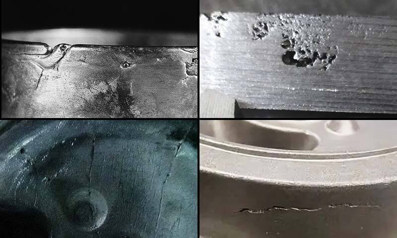
Common sheet metal defects include laser cutting dross, bend cracking, springback deviation, stamping wrinkles, and weld distortion. Resolving these defects requires tracing the physical symptom back to specific tooling setups, machine parameters, or DFM flaws before attempting any rework or batch rejection.
When a metal cabinet door scrapes its frame during final assembly, the defect rarely starts at the hinges—it usually starts three operations ago. A slight thickness variation from the steel mill affects the press brake’s bending angle, which in turn causes the welding fixture to pull the frame out of square.
Troubleshooting sheet metal fabrication isn’t just about rejecting out-of-tolerance parts; it is about tracking dimensional shifts across multiple manufacturing steps. The quick reference table below aligns common physical symptoms with the initial inspection points our Shengen engineers use on the shop floor.
| Visual Symptom | First Inspection Point | Suspect Operation |
|---|---|---|
| Dross on the bottom of a laser-cut edge | Check if dross is concentrated at corners, small holes, or distributed along the entire cut line. | Laser Cutting |
| Cracks starting at the intersection of a cut edge and a bend line | Examine the edge condition of the unbent flat blank at that specific location. | Blanking / Bending |
| Inconsistent angle along a single long bend line | Compare the angle readings at the left, center, and right sections of the bend. | Press Brake (Bending) |
| Flange wrinkling on a deep-drawn part | Observe if wrinkles are concentrated on one side or distributed evenly around the flange perimeter. | Stamping / Forming |
| Pinholes appearing along a weld seam | Inspect the pre-weld joint for oil, moisture, or other residual contaminants. | Pre-Weld Prep / Welding |
| Cabinet door scrapes the upper frame | Check the door panel, hinge alignment, and frame clearances relative to the contact point. | Assembly / Thermal Distortion |
Find Where the Defect Started
Pinpointing a defect’s origin saves time and rework costs. By tracking patterns and measuring between operations, you can identify exactly which step caused the issue.
Defect Location and Pattern
Record the defect’s exact location, direction, and frequency across the batch. If a V-die impression or scratch appears in the exact same spot on every piece, verify the contact points on the press brake or stamping tools. If surface scratches appear randomly, trace the material handling, transport, and stacking procedures between stations. For each pattern, isolate the variable—for example, running a single blank through the handling sequence without bending it—to confirm the root cause.
Measurements Between Operations
Using the cabinet assembly as an example, establishing a strict measurement sequence isolates dimensional shifts. First, verify the door panel dimensions and hinge positions. Next, measure the cabinet opening width at three points (top, middle, and bottom) and check both diagonals.
Maintain the same datum references throughout the evaluation. Compare the relevant dimensions recorded after bending, after welding and cooling, and after powder coating. If intermediate quality records are missing, use retained first-article inspection (FAI) samples or process a new test piece to re-establish the operation-by-operation baseline. At Shengen, tying FAI and routine sampling data to specific tooling and material batches allows our engineers to trace a dimensional shift back to tool wear or a specific material heat lot within an hour.
Check Cutting and Bending Defects
Cutting and bending are the most common sources of sheet metal defects. Identifying whether the issue stems from tooling, thermal stress, or material properties is the first step to a permanent fix.
Burrs and Laser Dross
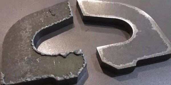
Identifying the defect type immediately narrows down the root cause. Mechanical burrs from punching or shearing indicate a tooling issue, while dross (resolidified metal) on laser-cut edges points to thermal parameter mismatches.
- Mechanical Burrs: If a punched edge feels sharp and jagged, the punch-to-die clearance is likely incorrect for the material thickness. Mild steel typically requires a clearance of 8–10% of the material thickness, while stainless steel needs 10–12%. Tool wear or misalignment will also push the material rather than shearing it cleanly.
- Laser Dross: Dross removal adds unnecessary manual deburring costs. If hard, difficult-to-remove dross appears on stainless steel parts, verify the nitrogen assist gas pressure; insufficient pressure fails to blow the molten metal clear. If dross only occurs at sharp corners, the laser is likely dwelling too long, requiring a reduction in cornering speed or adjustments to the pulsing frequency.
Thermal Distortion
When long, narrow strips or densely perforated panels warp, internal thermal stress is the culprit. Instead of trying to flatten a warped part post-cutting, the solution lies in CAM programming. Altering the cutting path to distribute heat evenly across the blank—using techniques like flying optics (skip cutting) or leaving micro-joints to secure the part until the end of the run—prevents the metal from releasing its stress unevenly. For extremely heat-sensitive thick plates, switching the process entirely from laser to waterjet cutting is often the most cost-effective DFM recommendation.
Bend Cracks and Distorted Holes
Bending parallel to the material grain is a guaranteed path to cracking on the outside radius, especially in hard alloys like 6061-T6 aluminum. Flat patterns must be nested so that critical bend lines run perpendicular (or at least 45 degrees) to the rolling direction. Additionally, verify the inside bend radius. As a rule of thumb, the inside radius should be at least 1T (one times material thickness) for mild steel, and 2T to 3T for harder aluminums to prevent outer-radius fracturing.
If a crack propagates from a free edge intersecting the bend, inspect the initial cut quality of the blank; micro-fractures from laser cutting often expand during forming. If circular holes distort into ovals after bending, verify the flat pattern geometry and ensure the distance from the hole edge to the bend line meets the minimum required distance for that material thickness and V-die setup.
Springback, Uneven Angles, and Flange Size
Different dimensional errors require specific troubleshooting paths on the shop floor.
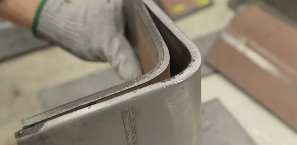
- Overall angle out of tolerance: This is typically caused by material springback. For high-yield-strength materials, standard air bending may not suffice. The process may require bottoming or coining to plastically deform the material and lock in the angle, or adjusting the overbend compensation in the press brake program.
- Inconsistent angle along the bend line: If the angle varies between the left, center, and right sections of a long bend, the issue is machine deflection. When the press brake rams bend under load, the center angle opens up. The solution is adjusting the machine’s CNC crowning (deflection compensation) settings, not changing the punch depth.
- Angle is correct, but flange dimension is out of tolerance: Trace the issue back to the flat blank. Check the locating edge used against the backgauge, verify the overall dimensions of the flat blank, and audit the bend deduction (K-factor) data used in the CAD unfold.
Check Stamping, Welding, and Surface Defects
Defects in secondary operations often ruin perfectly cut and bent parts. Knowing exactly what to inspect at the press or welding bench keeps scrap rates down and assemblies moving.
Stamping Wrinkles, Thinning, and Splits
When troubleshooting a deep-drawn part, divide it into three inspection zones: the flange, the side wall, and the corner radius. If wrinkles appear on the flange, the issue is typically inadequate blank holder force (pad pressure) or excessive material flow into the die cavity.
Conversely, if the side wall or corner radius thins excessively or splits open, the material is stretching because it cannot flow freely. To fix this, inspect the punch radius and identify where the draw stress is concentrated. Because adjusting blank holder force to cure a wrinkle can induce a split, you must re-check both the flange and the corner radius simultaneously after every die adjustment.
Weld Porosity and Part Distortion
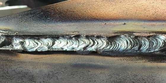
Pinholes or porosity in a weld seam compromise structural integrity and always trace back to contamination or shielding gas issues. Before modifying TIG or MIG welding parameters, inspect the pre-weld joint for residual cutting oils, moisture, or rust, and verify the shielding gas mixture (such as the Argon/CO2 ratio) and flow rate.
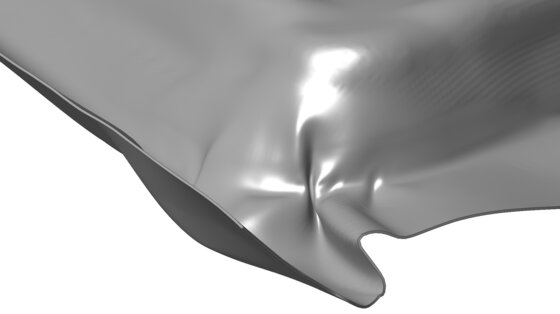
When a welded assembly distorts out of tolerance, compare the dimensions measured before welding to those taken after the part has completely cooled. If the distortion is significant, audit the pre-weld joint gaps, the tack welding sequence, and the clamping fixture design to ensure heat input is balanced across the assembly. Documenting the joint with photos before and after welding helps trace dimensional shifts back to specific anchor points.
Die Marks, Scratches, and Coating Defects
Surface defects render cosmetic parts unacceptable, regardless of dimensional accuracy. If parallel V-shaped indentations appear along the bend line, inspect the shoulders of the press brake bottom die. For parts with strict cosmetic requirements, such as brushed aluminum or polished stainless steel panels, applying urethane tooling film during bending prevents metal-to-metal contact, though it requires re-verifying the bend angle.
If “orange peel” textures or pinholes appear after powder coating, do not immediately blame the powder formulation. Compare photos of the raw substrate with the finished part, and audit the pre-treatment washing process (such as degreasing and phosphating), the substrate’s surface roughness, and the oven curing temperature to isolate the root cause.
Prevent Defects Before and During Production
The most cost-effective way to handle defects is engineering them out before cutting the first blank. A proactive approach ties the design intent directly to shop-floor quality checks.
Drawing and Material Requirements
A robust manufacturing drawing leaves no room for interpretation on the shop floor. Clearly call out the material grade, temper, and thickness, alongside the required inside bend radii, hole locations, and bend relief notches. Utilize proper Geometric Dimensioning and Tolerancing (GD&T) to identify critical-to-function assembly dimensions.
Designate primary visual surfaces (A-sides) and specify masking locations for painting or plating. When Shengen’s engineering team recommends a tighter radius or moving a hole further from a bend line, we explicitly state the material temper and tooling setup necessary to achieve that geometry without fracturing or distorting.
First-Part and In-Process Checks
Establish an inspection plan where the measuring tool matches the specific feature and operation. During material receiving, verify the alloy, temper, and actual sheet thickness against the mill certs; a slight thickness variation throws off the entire bending sequence.
During First Article Inspection (FAI), use a protractor or laser angle measurement for bend angles, and precise pin gauges for critical holes. Anytime a material heat lot changes, a tool is swapped, or a machine parameter is adjusted, immediately re-verify the specific features affected by that change before resuming the production run.
Decide Whether to Accept, Rework, or Reject the Part
When a defect is identified, the decision to accept, rework, or scrap the part must be based on objective criteria, not just visual appeal. A structured containment and review process prevents minor issues from snowballing into assembly failures.
Batch Containment and Acceptance Criteria
Upon discovering a batch anomaly, immediately quarantine the suspect parts and issue a Non-Conformance Report (NCR). Use production logs to trace back to the last known good part (the last passing FAI or routine inspection) to define the exact scope of the containment. Next, evaluate the defect against the print’s geometric tolerances, cosmetic limit samples, and functional assembly requirements.
For instance, a minor V-die impression on a hidden bracket might be acceptable, whereas the same mark on an A-side cosmetic panel is an automatic rejection. If a part’s dimensions are slightly out of tolerance but it still passes a physical fit-up test without forcing the assembly, the decision to accept it “as-is” must be formally authorized through a Material Review Board (MRB) or a formal deviation approval process by the relevant engineering authority.
Rework and Reinspection
Reworking a part is often more cost-effective than scraping it, provided the rework doesn’t introduce secondary defects. Every rework operation must be paired with a specific reinspection step. If parts are manually deburred or ground to remove laser dross, re-measure the affected overall dimensions and ensure no sharp edges remain.
If a painted surface is touched up, verify color matching under proper lighting and check the masking zones to ensure critical mating surfaces remain bare. If a warped cabinet is mechanically straightened, verify that the forced correction didn’t induce micro-cracks at the bend radii. Then, re-measure the opening widths, diagonals, and hinge hole alignments, followed by another physical trial assembly with the door panel to guarantee proper function.
Verification and Release
Returning to our scraped cabinet door example: the issue was traced through dimensional checks to excessive thermal distortion during the welding phase, which pulled the upper frame out of square. The out-of-tolerance frames were quarantined, mechanically straightened, verified for structural integrity, and successfully trial-fitted before being released to powder coating.
More importantly, to close the Corrective and Preventive Action (CAPA) loop, Shengen engineers adjusted the welding fixture and modified the tack-welding sequence for all subsequent batches. By linking every shop-floor defect back to a measurable process parameter, you transform troubleshooting from a guessing game into a repeatable quality control engine.
Hey, I'm Kevin Lee

For the past 10 years, I’ve been immersed in various forms of sheet metal fabrication, sharing cool insights here from my experiences across diverse workshops.
Get in touch
Kevin Lee
I have over ten years of professional experience in sheet metal fabrication, specializing in laser cutting, bending, welding, and surface treatment techniques. As the Technical Director at Shengen, I am committed to solving complex manufacturing challenges and driving innovation and quality in each project.