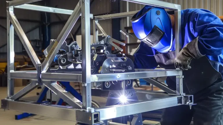
A welded assembly is a permanent metal structure created by fusing fabricated components—such as laser-cut sheet metal, machined parts, or tubing—into a single functional unit. The process requires precise fit-up, controlled heat input, and strict dimensional tolerances to ensure structural integrity and mechanical alignment.
But a successful welded assembly is more than just a strong weld bead. For engineers and procurement teams, the real challenges happen off the torch: controlling thermal distortion, holding tight mating tolerances across large frames, and preventing hidden post-weld finishing costs from inflating the final unit price.
This guide breaks down the welded metal fabrication process from a Design for Manufacturability (DFM) perspective. Instead of basic welding theory, we will cover how to design for efficient fit-up, choose the most cost-effective process, control post-weld dimensions, and structure your RFQ to avoid supplier guesswork.
The typical manufacturing sequence follows this path:Part Preparation → Fit-Up → Tack Welding → Welding → Cooling and Inspection → Finishing → Final Acceptance
Use the table below to navigate directly to the production phase you need to resolve:
| Your Challenge[cite: 51] | Relevant Section[cite: 51] |
|---|---|
| Complex structures require excessive assembly time[cite: 51] | Design Parts for Efficient Fit-Up and Welding[cite: 51] |
| Unsure which welding method fits the application[cite: 51] | Choose a Welding Process for Your Assembly[cite: 51] |
| Post-weld distortion causes mounting holes to misalign[cite: 51] | Control Distortion and Meet Assembly Tolerances[cite: 51] |
| Supplier quotes vary significantly for the same drawing[cite: 51] | Compare Total Cost at Your Production Volume[cite: 51] |
| Sample quality and production batch acceptance do not match[cite: 51] | Define Acceptance Criteria Before Placing an Order[cite: 51] |
Design Parts for Efficient Fit-Up and Welding
The goal in this phase is to reduce assembly difficulty and minimize unnecessary welding while fully satisfying the structural and functional requirements of the part.
Functional Requirements
Start by defining the load capacity, sealing needs, mounting interfaces, cosmetic standards, and operating environment. Determine which connections must be permanently welded and which require bolted joints for future disassembly. Mark the critical interfaces and areas needing strict control directly on the manufacturing drawings.
For example, a custom equipment enclosure has distinct zones: the bottom mounting base requires strict flatness tolerances for installation, the door frame needs precise dimensional control for an IP-rated seal, the exterior panels require a clean cosmetic finish with no visible weld marks, and the internal support brackets prioritize structural strength over appearance.
Part Consolidation
Evaluate whether press brake bending can replace separate plates and eliminate full-length welded joints. Consolidating parts through bending reduces heat input, mitigates distortion risks, and cuts down on manual post-weld grinding.
However, do not blindly eliminate welds if it compromises the overall build. You must check bend clearances, flat pattern limits, and material yield. If a single complex bent part reduces sheet metal yield by 40% or makes secondary CNC machining impossible, keeping two simpler welded parts is often the more cost-effective engineering choice.
Location and Access
Do not leave welders to measure and position parts manually on the fixture. Design locating edges, alignment holes, hard stops, or tab-and-slot (mortise and tenon) features into the flat patterns. Self-locating features can reduce fixturing and setup time by 30% to 50%.
Specify practical assembly gaps that accommodate standard laser cutting and bending deviations (typically 0.2mm to 0.5mm). Finally, verify physical access. A joint that looks robust in CAD is not viable if the welding torch, clamping fixtures, or grinding tools cannot reach it at the correct angle.
Choose a Welding Process for Your Assembly
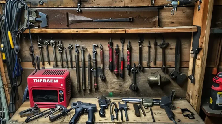
Material properties, joint geometry, and production volume dictate the correct welding process. Selecting the wrong method often leads to excessive heat distortion or skyrocketing labor costs from post-weld cleanup.
Material Compatibility
Confirm the material grade, temper, thickness, and surface condition (e.g., mill scale, oiled, or pre-galvanized). This dictates the required heat input, shielding gas, and pre-weld preparation. Depending on the application, specific welding codes like AWS D1.1 (for structural steel) or AWS D1.2 (for aluminum) may dictate the allowable procedures and inspection levels.
If the assembly involves dissimilar metals—such as aluminum to steel—standard fusion welding is generally not viable due to the formation of brittle intermetallic compounds. These joints require mechanical fastening (riveting), structural adhesives, or specific solid-state welding technologies.
Process Comparison
Different welding methods handle fit-up variations, heat input, and finishing costs differently. The table below outlines how common processes align with typical fabrication requirements:
| Comparison Item[cite: 52] | MIG/MAG[cite: 52] | TIG (GTAW)[cite: 52] | Laser Welding[cite: 52] | Resistance Spot[cite: 52] |
|---|---|---|---|---|
| Typical Joints[cite: 52] | Structural frames, heavy brackets, medium-to-thick plates (>3mm).[cite: 52] | Thin-wall enclosures, precise joints, exposed cosmetic seams (0.5mm – 3mm).[cite: 52] | Thin-to-medium sheet metal, continuous straight seams (1mm – 4mm).[cite: 52] | Overlapping thin sheets, internal stiffeners, light brackets.[cite: 52] |
| Fit-Up Conditions[cite: 52] | Tolerates moderate gaps (up to 1-2mm); standard fixturing is usually sufficient.[cite: 52] | Requires tight fit-up and clean joints; highly sensitive to gaps.[cite: 52] | Requires highly accurate fit-up (near-zero gap) and precision clamping.[cite: 52] | Requires overlapping flanges and physical access for electrode clamping.[cite: 52] |
| Production Characteristics[cite: 52] | High deposition rate; faster travel speeds; adds filler metal quickly.[cite: 52] | Slower travel speeds; precise heat control; highly dependent on operator skill.[cite: 52] | Extremely fast travel speeds; concentrated heat; requires enclosed safety cells.[cite: 52] | Very fast cycle times per spot; no filler metal or shielding gas required.[cite: 52] |
| Finished Part Requirements[cite: 52] | Higher heat input causes distortion; spatter requires manual grinding, increasing labor costs.[cite: 52] | Minimal spatter; highly aesthetic weld bead; low distortion on thin parts.[cite: 52] | Minimal heat-affected zone (HAZ); virtually no distortion; requires zero to minimal finishing.[cite: 52] | Localized indentations at weld spots; minimal overall distortion.[cite: 52] |
Production Conditions
The right process depends heavily on your production volume. Manual welding handles part-to-part variations efficiently, making it practical for prototypes and high-mix, low-volume batches.
Automated and robotic welding systems require strict consistency. If upstream laser cutting and bending tolerances fluctuate, the robot will fail to place the weld correctly. When submitting a Request for Quote (RFQ), it is highly recommended to partner with a manufacturer that offers multiple welding processes in-house. This prevents your design from being forced into a heavy MIG process simply because the supplier lacks a precision laser welding cell.
Control Distortion and Meet Assembly Tolerances
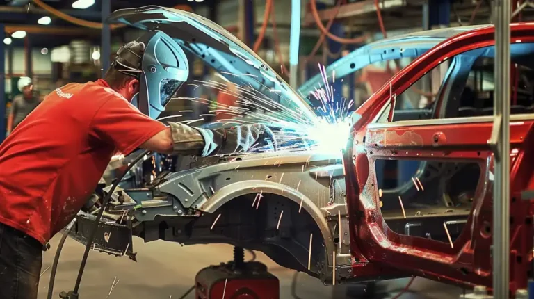
Applying excessive heat to metal causes it to expand, and cooling causes it to contract. This thermal cycle pulls the assembly out of alignment. If distortion is not controlled, mounting holes will miss their targets, and mating faces will not seal. A warped structural frame cannot simply be “bent back,” and attempting to mechanically force it into tolerance later usually costs more than the initial fabrication.
Datums and Tolerances
Begin by establishing clear datums derived directly from the assembly’s functional requirements—typically mounting faces, bearing housings, or sealing flanges.
You must separate component-level dimensions from assembly-level interface dimensions. A common engineering mistake is applying strict precision-machining tolerances across an entire welded structure.
The Supplier’s Perspective: When a manufacturer receives an RFQ with blanket ±0.1mm tolerances across a 2-meter welded frame, they immediately add a “risk premium” to the quote to cover anticipated rework, or they simply decline to bid. Applying appropriate general tolerances for welded structures (such as ISO 13920 Class B or C) signals that you understand fabrication, ensuring you receive competitive, honest pricing.
Apply tight tolerances exclusively to critical functional interfaces, and allow the rest of the non-mating structure to float within standard fabrication limits.
Fixturing and Sequence
A fixture serves two distinct purposes: locating the part against the datum, and clamping it to resist thermal movement. Clamping does not replace proper locating.
The manufacturing sequence must dictate a clear order of operations: locate, clamp, tack weld, and then fully weld. Set a strict dimensional inspection node immediately after tack welding. If the assembly is out of tolerance at the tacking stage, it is relatively cheap to break the tacks and reset. Once fully welded, the error is locked in permanently.
To minimize distortion, the procedure should specify a staggered weld sequence. Distributing the heat evenly across the structure—rather than welding continuously from one end to the other—significantly reduces warping on large assemblies.
Post-Weld Dimensions
Never measure a welded assembly while it is hot or still clamped in the fixture. The true dimensions of the part are only revealed after it has fully cooled, unclamped, and undergone any necessary mechanical straightening.
For high-precision features—such as bearing alignment bores or pump mounting pads—do not rely on the welding process to hold final tolerances. Instead, design a post-weld machining allowance (typically leaving 2mm to 3mm of extra material on the pads to be CNC milled after the frame has cooled and stabilized).
Compare Total Cost at Your Production Volume
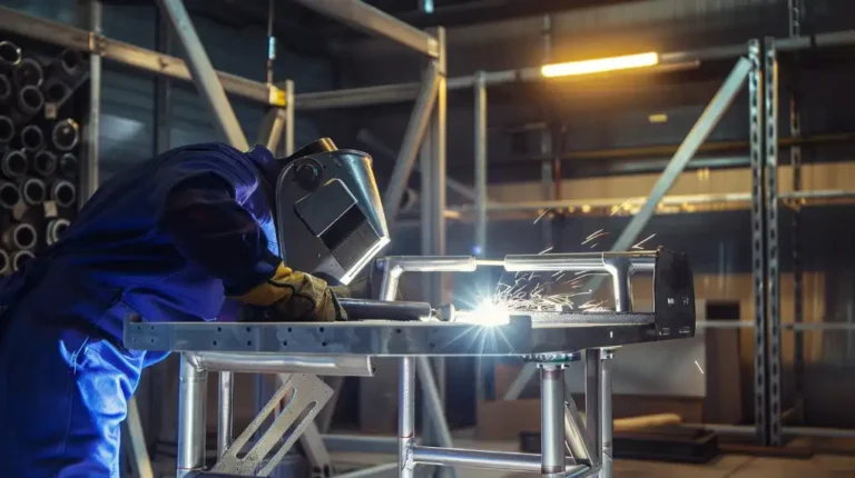
When comparing quotes from different suppliers, looking only at the bottom-line unit price is misleading. You must understand what drives the cost and how different manufacturing plans scale with your production volume.
Cost Structure
A professional B2B quotation typically breaks down costs into three distinct categories. Clarify with your supplier which fees are billed upfront and which are amortized into the piece price:
| Cost Category[cite: 53] | Key Elements Included[cite: 53] |
|---|---|
| One-Time Costs (NRE)[cite: 53] | Engineering review, custom fixturing, robotic programming, and First Article Inspection (FAI) reports.[cite: 53] |
| Per-Unit Manufacturing Cost[cite: 53] | Raw materials, standard hardware, laser cutting, bending, assembly, welding arc-time, post-weld finishing, and quality inspection.[cite: 53] |
| Delivery Costs[cite: 53] | Custom crating, anti-corrosion packaging, and agreed-upon freight services.[cite: 53] |
Welds and Finishing
Do not estimate welding costs solely by the price per meter of weld bead. The actual labor cost is heavily influenced by joint accessibility and part handling. An assembly that requires the operator to unclamp, manually flip via overhead crane, and re-clamp three times will cost significantly more than a part welded in a single setup on a rotary positioner.
Furthermore, post-weld finishing is often the most expensive hidden cost in metal fabrication.
Cost Trap: A drawing note that dictates *”grind all welds flush”* on non-visible structural joints can easily increase your per-part labor cost by 40% to 60%, while simultaneously reducing the joint’s load-bearing capacity by removing the weld throat thickness. Only specify flush grinding for highly visible cosmetic faces or mechanical interference zones. Leave structural welds in the “as-welded” condition whenever possible.
Volume and Automation
Robotic welding is not an automatic solution for cost reduction; its viability depends strictly on volume and setup times.
When evaluating automation, you must separate annual demand from batch size. For example, if you need 5,000 parts per year but order them in sporadic batches of 50, the 4-hour changeover and programming time for a robotic cell will erase any cost savings. In this scenario, manual welding utilizing universal modular fixtures remains more cost-effective. Conversely, for a single continuous run of 1,000 units, amortizing the upfront fixture and programming costs makes automated welding highly competitive, while simultaneously guaranteeing consistent bead quality.
Define Acceptance Criteria Before Placing an Order
Discrepancies between what you expect and what the factory delivers almost always stem from vague acceptance criteria. If the quality standard is not explicitly defined in the Request for Quote (RFQ), the supplier will quote based on the most economical interpretation, leading to disputes upon delivery.
Drawing and Finish Requirements
A drawing note that simply states *”weld securely”* or *”grind all over”* forces the supplier to guess your functional intent. Guesswork introduces risk, and suppliers cover risk by inflating the piece price.
Instead, use standardized welding symbols (such as AWS A2.4 or ISO 2553) to specify the exact weld type, leg size, length, and location. For intermittent welds, clearly state the pitch. Beyond the welds themselves, the drawing must explicitly mark:
- Grinding zones: Where welds must be flush for mechanical interference or cosmetic reasons.
- No-weld / No-spatter zones: Areas like tapped holes, machined mating surfaces, or sliding tracks that must be strictly protected during fabrication.
- Surface treatment: Masking requirements for powder coating, plating, or painting.
Inspection and First Article
You must define how the assembly will be inspected before issuing the purchase order. Break the inspection down into specific categories: dimensional tolerances, weld integrity, cosmetic appearance, and functional fit.
Specify the exact testing method and acceptance criteria. Do not over-specify Non-Destructive Testing (NDT) just to “be safe.” Demanding Ultrasonic Testing (UT) or Radiographic Testing (RT) on non-critical frame welds can make the inspection process cost more than the welding itself. Reserve UT/RT for pressure vessels or high-stress, load-bearing joints. For standard structural assemblies, Visual Testing (VT) and dimensional checks are usually sufficient.
Pro Tip for FAI (First Article Inspection): Insist that your supplier manufactures the First Article using the exact same fixtures, welding parameters, and automated cells intended for the final production batch. A beautiful, hand-crafted prototype made by a master toolmaker does not validate a scalable production process.
Once the FAI is approved, retain the signed report and a physical “golden sample.” Establish a clear rule with your supplier: any future changes to the welding procedure, fixtures, or material grades require a new first-article validation before batch production can resume.
Request a Welding Assembly Review
Send your drawings, material specifications, quantities, and inspection requirements. Our engineers will review joint access, locating features, tolerance risks, and the proposed manufacturing route.
Hey, I'm Kevin Lee

For the past 10 years, I’ve been immersed in various forms of sheet metal fabrication, sharing cool insights here from my experiences across diverse workshops.
Get in touch
Kevin Lee
I have over ten years of professional experience in sheet metal fabrication, specializing in laser cutting, bending, welding, and surface treatment techniques. As the Technical Director at Shengen, I am committed to solving complex manufacturing challenges and driving innovation and quality in each project.