When parts don’t fit or cost too much to make, poor design is often the cause. Many engineers face these problems, especially in early prototypes. With tight timelines and strict budgets, avoiding common issues from the start is key. Good design helps reduce cost, improve part performance, and simplify production.
Many people know how a part should look, but don’t know how metal forming affects it. This guide clears that up and shows how to design better.
What Is Sheet Metal Design?
Sheet metal design involves planning how to shape and cut metal parts using simple rules that match the factory’s work. The goal is to make parts that are easy to bend, cut, and assemble without wasting material or slowing production. A well-designed part fits well, works well, and controls costs.
Good design makes parts easier to make and assemble. It also reduces waste. Designers consider things like how metal moves when bent, or how easy a shape is to cut. Good planning means fewer problems and lower costs.
Design Principles and Best Practices
Wise design choices help avoid delays and reduce costs. These principles make parts easier to produce, stronger, and more reliable.
Designing for Manufacturability (DFM)
Designing for manufacturability means making parts easy to produce with available machines: simple bends, standard hole sizes, and consistent features help. Avoid deep draws or tight corners that need special tools. Use uniform bend radii. Place features far from edges to avoid distortion during bending.
Avoiding Common Design Errors
Sharp internal corners can crack during bending. Tiny holes near bends may stretch or tear. Too many bends increase the cost. Placing bends too close together can weaken the part. Also, mismatched tolerances make it hard to assemble. These mistakes slow production and raise costs.
Keeping Cost and Efficiency in Mind
Simple designs cost less. Fewer bends, holes, and cuts mean faster production. Avoid features that need custom tools. Standard materials and thicknesses reduce lead times. Designing flat parts that nest nicely on a sheet saves material. Think about assembly, too. Easy-to-align parts save labor.
Sheet Metal Design Parameters
Getting familiar with basic sheet metal parameters makes your design practical and cost-effective. These parameters control how metal behaves during bending, ensuring your part comes out accurately and without defects.
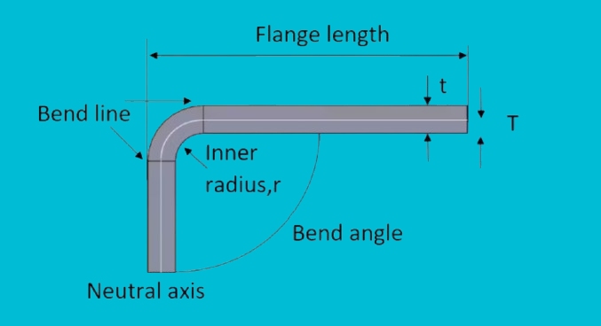
Bend Radius
Bend radius is the curve formed when sheet metal bends. It’s measured at the inside of the bend. Choosing the right bend radius matters because a too small radius stresses the metal. This can cause cracks or tears.
A safe rule is to use a bend radius equal to the metal’s thickness. For example, if your metal is 2 mm thick, the bend radius should be at least 2 mm.
A slightly larger radius makes the metal easier to bend and helps prevent defects. Larger radii also put less stress on the metal, increasing its strength and durability after forming.
K-Factor and Y-Factor
When sheet metal bends, it stretches on the outside and compresses on the inside. The K-factor helps you predict this behavior. It shows where the metal doesn’t change length within the thickness, called the neutral axis.
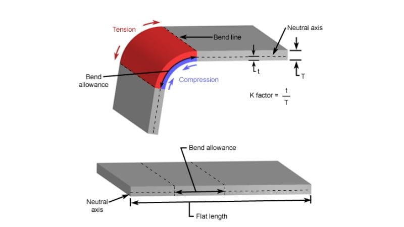
Common K-factors are between 0.3 and 0.5. A K-factor of 0.5 means the neutral axis is halfway through the metal thickness. Lower K-factors mean the neutral axis is closer to the inside of the bend.
The Y-factor is similar, but less common. It helps calculate the bend allowance directly. Both factors ensure your flat metal cutouts bend accurately into their final shapes.
Bend Allowance and Bend Deduction
Bend allowance tells you how much extra length you must add to the flat sheet to make the bend accurately. When metal bends, it doesn’t just fold—it stretches slightly. Without accounting for bend allowance, your finished parts would be too short.
On the other hand, deductive reasoning is the opposite concept. It’s how much length you subtract from the total flat length because of the bend.
Using these numbers correctly ensures that your final part matches your design exactly after bending. It prevents errors, wasted metal, and unnecessary rework.
Hole and Slot Distances
Putting holes or slots too close to bends can deform or weaken your part. The metal around a bend stretches and compresses. This stress affects nearby holes, causing them to warp or become oval-shaped.
A good rule is to place holes or slots at least two to three times the metal thickness away from the bend line. For example, if your sheet metal is 1 mm thick, place holes at least 2-3 mm away from any bend.
Following this guideline prevents distortion and ensures that parts align correctly during assembly.
Minimum Flange Length
A flange is a bent edge to strengthen parts or provide attachment points. If a flange is too short, you’ll have difficulty bending it accurately. It can even weaken the part or cause inaccuracies during manufacturing.
A safe minimum flange length is generally four times the metal’s thickness and bend radius. For instance, if your metal is 1 mm thick and the bend radius is 2 mm, the flange should be at least 6 mm long (4 × 1 mm thickness + 2 mm radius).
Longer flanges make bending easier and improve part strength. Following these minimum lengths helps avoid issues during production.
Bending Considerations
Knowing how bending affects sheet metal helps prevent common fabrication problems. It ensures your parts fit and perform correctly in the real world.
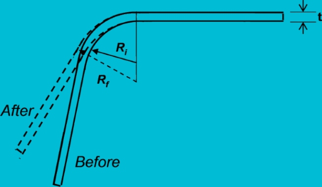
Springback and How to Compensate
Springback is when metal tries to return to its original shape after bending. It’s common in almost all metals. After you bend a sheet, it doesn’t stay at the exact angle you set—it springs back slightly.
You must “over-bend” the metal slightly beyond your target angle to compensate. For example, if you want a 90-degree bend, you might initially bend to 92 or 93 degrees. When you release pressure, the metal springs back to your desired 90-degree angle.
The amount of springback varies by metal type, thickness, and the radius of the bend. Thicker metals and larger radii tend to have more noticeable springback. Always test bends or consult a bending chart to find accurate springback values for your material.
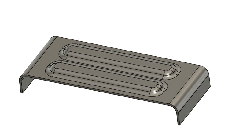
Hemming, Jogging, and Offset Bends
Hemming, jogging, and offset bends are special techniques that add strength, safety, or specific shapes to sheet metal parts.
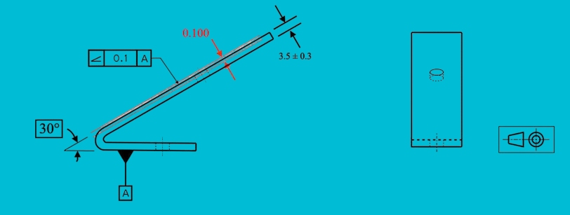
Hemming is folding the metal edge back onto itself. It strengthens edges and makes them safer to handle, removing sharp edges. A typical hem has two stages: bending at a 30-45-degree angle and then fully folding the metal flat onto itself.
Jogging creates two opposite bends close together, forming a “step.” It helps join two sheet metal sections flush together without overlap. Jog bends require enough spacing between bends to avoid deformation. Keep spacing at least twice the metal thickness.
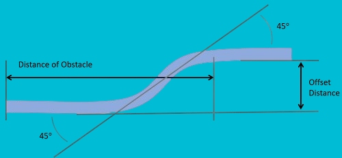
Offset bends move a part of the sheet metal sideways, forming parallel but shifted surfaces. These bends help parts fit together precisely, like in brackets or mounting plates. Leave enough space between bends—at least the metal thickness—to prevent distortion.
Cutting and Punching Features
Proper cutting and punching features ensure accurate parts, easier manufacturing, and better performance. Planning these details carefully prevents costly problems in production and assembly.
Hole Size and Positioning
Choosing hole sizes and positions carefully ensures good part quality and assembly ease. When punching holes, avoid making them smaller than the metal thickness. Small holes require special tools, and they wear out quickly.
Spacing between holes matters too. Keep holes at least two times the metal thickness apart. Holes placed closer can deform or stretch during cutting or bending.
Also, keep holes away from edges and bends. A safe distance is usually twice the metal thickness plus the radius of any nearby bend. Proper spacing prevents cracks, distortion, and weakness.
Corner Radii and Internal Cutouts
Sharp internal corners cause stress and weaken metal parts. They often lead to cracks or tearing, especially during bending. Always include a small radius on internal corners.
A recommended corner radius is at least half the metal thickness. Larger radii spread stress evenly, increasing durability and preventing cracking.
For internal cutouts, avoid narrow slots or complex shapes. They slow down production and often cause distortion. Simple, larger cutouts with rounded corners help maintain part strength and accuracy.
Tool Access and Reliefs
Tool access and relief cuts make manufacturing easier. Relief cuts remove small metal sections near bends, giving tools room to work. They reduce stress, helping the metal bend easily without distortion.
Place relief cuts carefully. Position them at corners or tight bends where metal could stretch or bunch up. Typically, reliefs are small slots or holes at intersections between bends.
Relief cuts save your parts from warping or cracking. They also make bending faster, smoother, and more precise. Always plan for proper tool clearance, especially when designing complex shapes.
Forming Features
Forming adds strength, functionality, or appearance improvements to your sheet metal parts. Good design of these features simplifies manufacturing and boosts part performance.
Countersinks and Counterbores
Countersinks are angled recesses around a hole. They let flat-headed screws sit flush with the surface. Counterbores create a flat-bottomed recess for screws or bolts, allowing their heads to be fully recessed.
Countersinks are quick and straightforward to create, ideal for thinner sheets. Counterbores require thicker material and more careful machining.
When planning countersinks, keep the angle around 82 or 90 degrees, common in standard screws. Avoid very shallow or deep countersinks that make screws fit poorly.
For counterbores, ensure the bottom surface is flat, and the hole is deep enough for the screw head. Avoid thin materials that can’t handle the depth needed for counterbores.
Lances and Bridge Features
Lances are cuts that partially detach metal tabs, creating small raised or angled sections. They secure wires or serve as stops or guides in assemblies.
Bridge features are similar, but raised sections with two parallel cuts are created. These bridges are often used as support points or for routing cables.
When designing lances, leave enough metal around the cuts. The tab should be wide enough to resist bending or breaking during use. Also, avoid placing lances too close to edges or bends to reduce distortion risk.
For bridge features, ensure cuts are parallel and have rounded edges. Avoid sharp corners that create stress points and possible tearing. Provide enough clearance underneath the bridge to insert wires or fasteners easily.
Tolerances and Fit
Proper tolerances ensure your parts fit well and perform reliably. Clear, realistic tolerances help avoid costly adjustments, assembly delays, and quality issues later.
Dimensional Tolerances for Laser Cutting
Laser cutting is accurate, but there are limits. Typical tolerances for laser-cut sheet metal parts range from ±0.005 inches (0.13 mm) to ±0.010 inches (0.25 mm). This tolerance depends on metal thickness and cutting speed.
Thinner metal allows tighter tolerances, while thicker material may have more variance. Fast cutting speeds produce rougher edges and less accuracy, while slower cutting speeds improve precision but increase cost.
When designing parts, leave extra space around critical areas. Holes and slots should include clearance for slight size variations. A good rule is to make holes about 0.01 inches (0.25 mm) larger than the bolt or screw size.
Bend Tolerances
Bending metal introduces more variability. Typical bend angle tolerances are ±1 to ±2 degrees. Bending thicker metal or using larger bending equipment may increase this tolerance slightly.
To manage these tolerances, avoid designs needing exact bends—plan for minor adjustments. Include slots or elongated holes to help align parts during assembly.
Also, limit the number of bends when possible. Each additional bend adds uncertainty, raising the risk of cumulative errors.
Flatness and Angularity
Flatness measures how much the surface of the metal deviates from being perfectly flat. Laser-cut sheet metal typically has flatness tolerances around 0.01 inches per foot (0.25 mm per 300 mm). Thinner sheets warp more easily during cutting, increasing flatness issues.
Angularity describes how accurately edges meet at correct angles. Standard angularity tolerance is usually ±1 degree. Tighter angularity tolerances need careful setup, precise machines, and slower production speeds.
Cost-Efficient Design Strategies
Efficient design helps save money and improve manufacturing. Keeping your design simple, practical, and easy to produce reduces costs significantly.
Reducing Part Count
Having fewer parts in your design is one of the best ways to lower costs. Each additional part needs more cutting, bending, assembly, and inspection. Fewer parts simplify the entire production process.
Combine multiple simple parts into one more complex piece to lower the part count. For example, design them as a single bent piece instead of welding two brackets together.
Reducing parts also makes inventory simpler. Fewer parts mean less paperwork, fewer storage costs, and faster assembly times. Always look for opportunities to merge parts or eliminate unnecessary components.
Designing Multi-Use Components
Multi-use components are parts designed to serve more than one purpose. A single part that performs multiple functions simplifies manufacturing and reduces overall cost.
For example, a sheet metal bracket might include slots or embossed features that align other components during assembly. This eliminates extra alignment parts or hardware.
Think creatively about how your parts can serve more than one function. Carefully placed bends, slots, or features let you combine tasks, making your parts more versatile.
Minimizing Material Waste
Reducing material waste directly lowers your production costs. Efficient designs nest nicely on sheet metal stock, using the smallest possible amount of material.
Design parts that fit neatly together when cut from a sheet to minimize waste. Square or rectangular shapes nest tightly, creating less scrap. Complex shapes or narrow cuts often generate more waste.
Also, keep consistent thickness throughout your designs. Mixing thicknesses requires multiple setups and wastes material. Standardizing metal thickness lets you use metal sheets more effectively.
Conclusion
Good sheet metal design combines clear thinking, thoughtful planning, and knowledge of how metal behaves during cutting, bending, and forming. Using proper bend radii, tolerances, hole spacing, and joining methods helps you avoid production issues and keeps your costs under control.
Looking for a supplier who understands these design rules and delivers high-quality sheet metal parts on time? Contact us today to get expert support on your next project. Let’s bring your design to life—quickly, accurately, and cost-effectively.
Hey, I'm Kevin Lee

For the past 10 years, I’ve been immersed in various forms of sheet metal fabrication, sharing cool insights here from my experiences across diverse workshops.
Get in touch
Kevin Lee
I have over ten years of professional experience in sheet metal fabrication, specializing in laser cutting, bending, welding, and surface treatment techniques. As the Technical Director at Shengen, I am committed to solving complex manufacturing challenges and driving innovation and quality in each project.
Related Resource

Fingerprint Resistant Stainless Steel: How It Works,and How to Choose


