In precision manufacturing, standard CNC machining and surface grinding eventually hit a physical limit. When a print calls for sub-micron flatness, absolute parallel surfaces, or a completely stress-free component, conventional abrasive machining falls short.
Lapping is a high-precision way to finish a part. You rub a workpiece against a flat plate, called a lap, using a watery mix of tiny abrasive grains. This process creates an incredibly flat and smooth surface.
As a final step in machining, it only removes a tiny bit of material. This is usually between 0.003 mm and 0.03 mm. It helps parts meet very strict size requirements. It works well on metals, ceramics, and glass to give them a perfect finish.
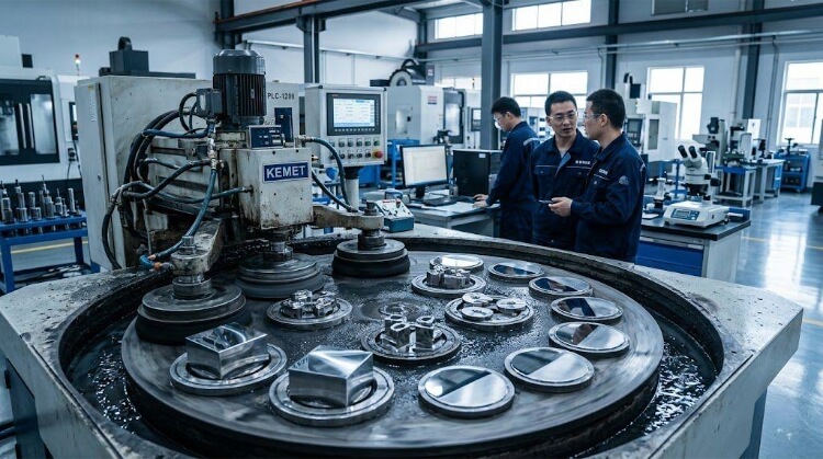
Why Some Precision Parts Still Fail After Grinding?
Grinding is highly efficient for sizing parts, but it is an inherently aggressive process. It relies on fixed abrasives, high spindle speeds, and rigid clamping—variables that introduce physical and thermal forces detrimental to extreme tolerances.
Flatness vs. Surface Finish
A common trap in manufacturing is confusing surface finish (Ra) with geometric flatness. A ground part can achieve a highly reflective, Ra 0.2 µm mirror-like finish, yet still be physically bowed or wavy by 0.02mm across its profile.
Because grinding wheels follow the linear, rigid path of the machine, any microscopic deflection in the spindle, machine bed, or the fixture itself translates directly into flatness errors on the workpiece.
Thermal Stress and Distortion
Grinding generates intense localized friction. Even with heavy flood coolant, this creates a Heat-Affected Zone (HAZ) on the material surface.
For high-value thin-wall components—such as aerospace 6061-T6 aluminum plates or 304 stainless steel flanges—this localized thermal expansion induces severe internal residual stress. The shop-floor reality is this: a part may measure perfectly flat while clamped tightly on the magnetic chuck, but the moment the magnet is turned off, the internal stress relieves. The plate instantly springs back and bows out of tolerance.
Lapping eliminates this entirely because it operates near room temperature with zero clamping force.
Sealing Surface Contact
Standard grinding leaves a distinct, directional grain pattern (lay) on the metal. In mechanical assemblies like hydraulic spool valves or fluid control manifolds, high-pressure gases or liquids can channel right through these microscopic directional grooves, causing leaks.
True zero-leakage sealing requires absolute metal-to-metal contact. A directional ground finish simply cannot reliably provide this level of mating surface area.
Hard and Brittle Materials
Advanced engineering materials like alumina ceramics, sapphire glass, and tungsten carbide wear rings possess extreme hardness but very low fracture toughness.
The rigid, high-speed impact of a bonded grinding wheel often causes micro-cracking and severe edge chipping. These materials require a finishing process that gently wears the surface away without the sudden mechanical shock of standard abrasives.
How Lapping Controls Surface Accuracy?
Instead of forcing a spinning wheel into a rigidly clamped part, lapping uses low pressure (typically 1 to 2 PSI), slow rotation speeds, and a stress-free environment to mechanically average out surface imperfections.
Loose Abrasive Cutting
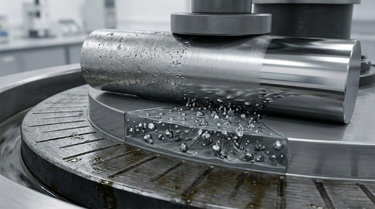
Lapping replaces bonded grinding wheels with a slurry—a precisely mixed compound of a liquid carrier (oil or water-based) and free abrasive particles. Depending on the material, this might be calcined aluminum oxide for soft metals, or 1-5 micron monocrystalline diamond for carbides.
This slurry is continuously fed into the gap between a rotating, heavy lapping plate (usually cast iron) and the workpiece.
Rolling and Micro-Cutting
As the lapping plate rotates, the abrasive particles become temporarily trapped. They constantly roll, tumble, and slide across the gap.
This continuous rolling action causes the microscopic sharp edges of the abrasives to take tiny “bites” out of the high spots on the part’s surface. Material is removed gradually, often at rates of just fractions of a micron per minute.
Surface Averaging Effect
The core mechanism of lapping is mechanical averaging. The workpiece is placed inside a conditioning ring and moves in a planetary, multi-directional motion across the perfectly flat plate.
Over time, the extreme physical flatness of the plate is transferred directly to the workpiece. Because the part is free-floating—held only by gravity or very light top weights—there are no external fixture stresses fighting the natural geometry of the metal.
Non-Directional Surface Finish
Unlike turning or surface grinding, the random, multi-directional kinematics of lapping leave no distinct grain pattern. The result is a uniformly matte, cross-hatched topography.
In mechanical engineering, this non-directional surface is highly functional. It maximizes the load-bearing contact area for mating parts and naturally retains microscopic oil films, preventing galling in heavy-duty sliding applications.
Where Lapping Fits in Manufacturing?
Because lapping is a slow, abrasive-wear process, it is never used for bulk material removal. From a manufacturing routing perspective, it sits at the absolute end of the line—the ultimate corrective step deployed only when CNC milling, turning, or precision grinding have reached their physical limits.
Machining Allowance Strategy
A frequent and costly mistake in process planning is leaving too much material for the lapping department. Because lapping removes material at fractions of a micron per minute, leaving an excessive allowance will skyrocket your cycle times.
⚠️ Procurement Trap: Using lapping as a bulk-removal process to fix sloppy CNC turning will instantly destroy your part’s profit margin. High-precision lapping machine-hour rates are expensive.
The shop-floor rule: Precision grinding or fine CNC turning should bring the part to within 0.01mm to 0.03mm (0.0004″ to 0.0012″) of the final thickness. Lapping should only be responsible for removing this final micro-layer to achieve the required flatness and Ra.
Final Surface Correction
Even the best precision grinders leave micro-errors: slight bowing, crowning, or tapering due to machine vibration or wheel wear. Lapping acts as the great equalizer. The heavy cast-iron lapping plate acts as a massive, perfectly flat geometric reference. It automatically targets and wears down the “high spots” on a workpiece, mathematically correcting the “potato chip” warping effect left by previous machining steps.
Thin-Wall and Non-Magnetic Parts
Workholding is the enemy of thin-wall precision. If you need to grind a 2mm thick titanium or aluminum plate, magnetic chucks are useless. If you use a vacuum chuck, the vacuum physically pulls the warped plate flat against the table. The grinder cuts a perfect plane, but the moment the vacuum is released, the metal springs right back to its warped state.
Lapping solves this through free-floating carriers. Parts are placed into nesting templates that simply guide them across the plate. Gravity provides the downward force. Zero clamping means zero induced stress, resulting in true, relaxed flatness.
Batch Processing Stability
Unlike CNC grinding—which is largely a serial, one-part-at-a-time process—lapping is highly efficient for batch production of small, critical components. A standard 36-inch planetary lapping machine can simultaneously process dozens of mechanical seals, ceramic washers, or valve plates.
Because all parts share the exact same conditioning rings and slurry environment, the dimensional stability and tolerance consistency across the entire batch are exceptionally high.
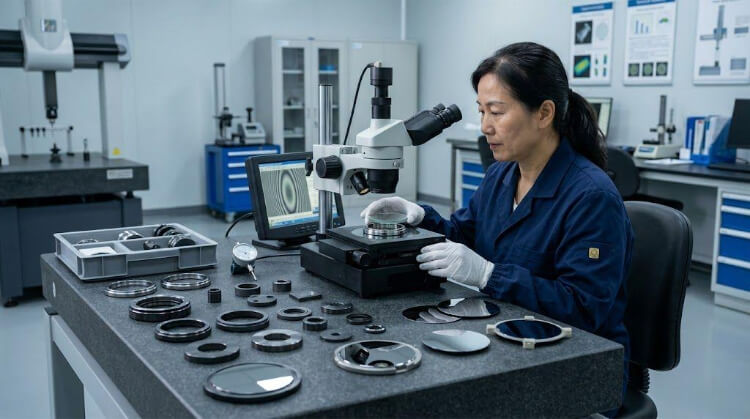
Measuring Flatness After Lapping
Standard shop tools like calipers, micrometers, or even standard CMMs (Coordinate Measuring Machines) lack the data density required to verify sub-micron flatness. After lapping, inspection shifts from mechanical probing to optical and physical metrology.
🌡️ The Thermal Trap (Crucial for QA): At sub-micron tolerances, thermal expansion is your biggest enemy. True flatness inspection must be conducted in a strictly temperature-controlled metrology lab (typically 20°C / 68°F). You cannot reliably verify a 2-light-band tolerance on a hot, fluctuating shop floor—the metal will literally move while you measure it.
Optical Flats
This is the gold standard for shop-floor flatness verification. An optical flat—a perfectly polished quartz glass disc—is placed over the lapped part under a monochromatic helium lamp. This creates visible interference fringes (light bands).
By counting these curved lines, an inspector can read the exact topography. One helium light band equals exactly 0.29 microns (11.6 micro-inches). If a print calls for “flatness within 2 light bands,” the shop must hold a physical flatness of ~0.58 microns.
Surface Profilometers
While optical flats measure macro-geometry (flatness), profilometers measure micro-texture. A diamond-tipped stylus is dragged across the lapped surface to measure the microscopic peaks and valleys. This is critical for verifying that the lapping slurry has fully removed the directional grinding marks and achieved the required non-directional Ra (Average Roughness).
Contact Pattern Inspection
For larger components where optical flats are impractical, engineers rely on physical contact mapping. A master granite surface plate is coated with a micro-thin layer of engineer’s blue (Prussian blue) compound. The lapped part is gently rubbed against the plate. When flipped over, the blue dye reveals the exact contact bearing area.
A high-quality lapped sealing surface will show a uniform, unbroken dye distribution across 90%+ of its surface—proving there are no low spots that could cause leaks.
Laser Interferometry
For ultra-critical aerospace, medical, and semiconductor components (like silicon wafers), human interpretation of light bands isn’t enough.
Laser interferometers provide non-contact, computerized topographical mapping. These systems fire a laser at the surface, instantly calculating thousands of data points to generate a highly detailed, 3D model of the part’s flatness, ensuring absolute compliance without physically touching the sensitive surface.
Lapping vs. Grinding vs. Honing
A common issue in mechanical design is specifying the wrong finishing process on a drawing. While grinding, honing, and lapping are all abrasive machining methods, they are not interchangeable. They solve entirely different geometric problems.
Material Removal Rate (MRR)
Grinding: The workhorse for precision sizing. It uses bonded wheels to remove material aggressively, often taking off millimeters per minute.
Honing: A moderate-removal process, typically removing 0.02mm to 0.1mm of material to achieve a final dimension.
Lapping: The slowest of the three. It removes material at the micro-level (fractions of a micron per minute). It is strictly a surface-correction process, not a bulk sizing process.
Heat and Residual Stress
Grinding: Generates intense friction and heat at the point of contact, requiring heavy flood coolant. It often leaves a Heat-Affected Zone (HAZ) and induces residual stresses that cause parts to warp.
Honing: Slower speeds and larger contact areas generate significantly less heat than grinding, minimizing part distortion.
Lapping: A “cold” process. Running at extremely low speeds (e.g., 40-80 RPM) and low pressures, lapping occurs essentially at room temperature, inducing absolutely zero thermal or mechanical stress into the workpiece.
Flat Surface vs. Internal Bore Finishing
Grinding: Versatile, capable of processing flat surfaces (surface grinding) and outside/inside diameters (cylindrical grinding), but leaves a directional surface lay.
Honing: Strictly an internal cylindrical process. It uses expanding abrasive stones to correct the roundness, straightness, and taper of internal bores (like engine cylinders), leaving a characteristic cross-hatch pattern for oil retention.
Lapping: Primarily used for external flat surfaces. It is the only process that can achieve true, non-directional sub-micron flatness across a wide plane.
Precision Limits
Grinding: Generally maxes out around 0.002mm (2 microns) for flatness.
Honing: Can hold bore diameter and cylindricity tolerances down to 0.001mm (1 micron).
Lapping: Can achieve flatness measured in light bands (0.3 microns) and Ra surface finishes down to 0.05 µm (2 micro-inches) or better.
| Feature / Parameter | Precision Grinding | Honing | Lapping |
|---|---|---|---|
| Primary Application | Bulk sizing, flat surfaces, external/internal cylinders | Internal cylindrical bores (e.g., engine cylinders, valves) | Extreme flatness, absolute parallelism, sealing surfaces |
| Abrasive Type | Bonded solid wheel | Bonded expandable abrasive stones | Loose abrasive particles suspended in a liquid slurry |
| Material Removal Rate | High (mm per minute) | Moderate (0.02mm – 0.1mm total allowance) | Very Low (Fractions of a micron per minute) |
| Heat & Residual Stress | High (Risk of HAZ, requires heavy flood coolant) | Low (Moderate friction, minimal distortion) | Zero / Cold (Room temp, completely stress-free) |
| Workholding / Clamping | Rigid (Magnetic chuck, vise, or vacuum plate) | Rigid or Gimbaled (Part or tool is rigidly held) | Free-Floating (Zero clamping force, gravity-fed) |
| Typical Precision Limit | ~2.0 µm (0.00008") | ~1.0 µm (0.00004") Cylindricity | ~0.3 µm (1 Light Band) Flatness |
| Surface Finish (Ra) | 0.2 µm – 0.8 µm | 0.1 µm – 0.4 µm | 0.05 µm or better |
| Surface Topography | Directional (Linear grain / lay) | Cross-hatched (Optimized for oil retention) | Non-directional (Matte finish, max contact area) |
Common Shop-Floor Problems During Lapping
Lapping is not a magic solution; it is a highly sensitive process. Because it operates at the microscopic level, tiny variables can cause immediate quality failures.
Edge Rounding
Because lapping relies on a liquid slurry, the abrasive fluid creates a microscopic “bow wave” as it hits the leading edge of the workpiece. This fluid dynamic causes the abrasive to cut slightly deeper at the very edges of the part, resulting in a microscopic radius or “roll-off” on what should be a perfectly sharp 90-degree corner.
Shop-floor fix: Using sacrificial “dummy rings” around the part to absorb the roll-off effect, keeping the actual part perfectly flat edge-to-edge.
💡 DFM Tip for Engineers: If a razor-sharp 90-degree edge is not functionally critical for your assembly, specify a small allowable edge break or undercut on your drawing. This eliminates the need for expensive dummy rings and reduces your unit cost.
Embedded Abrasives
When lapping softer materials like aluminum, copper, or 316 stainless steel, the metal is softer than the cast-iron lapping plate. Instead of rolling, the hard abrasive particles (like diamond or silicon carbide) can embed themselves directly into the soft metal surface. The part essentially becomes a lap itself, which will aggressively wear down any mating part in its final assembly.
Surface Scratches
In lapping, cleanliness is absolute. If a single 15-micron stray particle drops onto a lapping plate running a 3-micron slurry, that oversized particle will tear deep, looping scratches (called “pig-tails”) across the parts.
Because lapping is a batch process, a single contamination event doesn’t just ruin one part—it causes an instant 100% scrap rate for the entire run. This is why top-tier shops isolate their lapping machines in climate-controlled, cleanroom-like environments.
Plate Wear
The cast-iron lapping plate removes material from the part, but the part also wears the plate. If a shop runs too many small parts in the center of the plate, the plate will eventually wear into a concave bowl shape. Any parts lapped on a concave plate will inevitably come out convex.
Shop-floor fix: Continuous use of heavy conditioning rings that constantly re-flatten the plate during production.
Cleaning and Contamination Control
You cannot simply wipe down a lapped part and ship it. The slurry leaves a microscopic film of oil, metallic dust, and abrasives.
If not surgically removed, this leftover slurry will act as a grinding paste inside your final assembly, destroying high-pressure hydraulic seals or contaminating cleanrooms within hours of operation. Post-lapping parts must go through strict multi-stage ultrasonic cleaning lines immediately to pull embedded contaminants from the micropores of the metal.
Conclusion
Lapping is not the fastest finishing process, and it is not the right choice for every precision part. However, when a component requires extremely flat contact surfaces, low surface stress, or stable geometry after machining, lapping is often the process that solves the problem when grinding or CNC machining can no longer meet the requirement.
If your part needs tight flatness control, precise sealing surfaces, or stable finishing on hard materials, an early engineering check can help avoid many production problems before machining starts. This step can reduce rework, cost, and delays.
You can send us your drawings, tolerance requirements, or project details. Our team can then review your part and help you c
Hey, I'm Kevin Lee

For the past 10 years, I’ve been immersed in various forms of sheet metal fabrication, sharing cool insights here from my experiences across diverse workshops.
Get in touch
Kevin Lee
I have over ten years of professional experience in sheet metal fabrication, specializing in laser cutting, bending, welding, and surface treatment techniques. As the Technical Director at Shengen, I am committed to solving complex manufacturing challenges and driving innovation and quality in each project.