Compound die stamping is a sheet metal manufacturing process that performs multiple cutting operations, such as piercing and blanking, in a single press stroke at one station. It produces highly accurate, perfectly flat parts, making it cost-effective for medium-to-high volume production without progressive station transfers.
While the definition is straightforward, deciding whether to invest in compound tooling requires a strict engineering and financial evaluation.
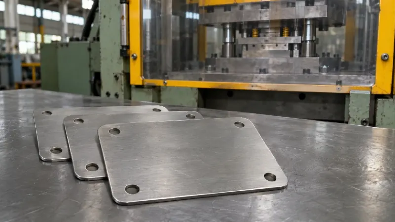
Consider a practical shop-floor example: a flat mounting plate measuring 80 × 50 × 1 mm, made of 304 stainless steel, featuring four Ø6 mm through-holes and R3 corners. During early prototyping, laser cutting works well while the drawing is still changing. Once the design stabilizes and order volumes increase, a compound die can stamp this exact profile in a fraction of a second.
Before cutting steel for a $6,000 tool, you must verify if your part geometry allows for simultaneous blanking and calculate exactly how many pieces you need to order to break even on the die cost.

When Is Compound Die Stamping a Good Fit?
Choosing the right stamping method dictates your production speed and unit price. Evaluate your part’s geometry and expected volume to see if a compound die makes financial sense.
Piercing and Blanking in One Stroke
In a compound die, two primary cutting actions happen in the same station almost simultaneously. Piercing cuts the four Ø6 mm holes, turning the internal slugs into scrap. Blanking cuts the 80 × 50 mm outer profile, separating the final mounting plate from the strip.

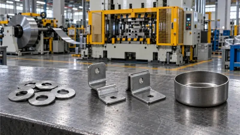
This differs fundamentally from progressive die stamping. In a progressive setup, the material strip advances through multiple stations—piercing the holes at station one, and blanking the perimeter at station three, for example. While a progressive die also outputs a finished part with every stroke, the material must index forward between actions. A compound die completes all cutting for a single part without moving the strip.
Flat Parts and Parts That Need Forming
The primary engineering advantage of cutting everything in one station is dimensional accuracy. For a round washer, this ensures the inner and outer diameters remain strictly concentric, often holding tolerances within ±0.02 mm. For our mounting plate, the distance between the four holes and the outer locating edges is fixed by the tool steel block itself. This eliminates the positional tolerance stack-up caused by repositioning parts across progressive stations.
Compound dies are tailored for flat parts. If a part requires forming, the manufacturing route usually changes. The table below outlines how geometry and order volumes dictate the process choice:
| Part Profile & Order Status | Primary Process Route to Evaluate |
|---|---|
| Flat prototype, drawing subject to change | Laser cutting |
| Flat part with holes, stable drawing (e.g., 5,000 - 50,000 parts) | Compound die stamping |
| Part with a single bend, volume unconfirmed | Laser cutting + press brake, or compound blanking + secondary bending |
| Part with multiple bends, continuous high volume (e.g., 100,000+ parts) | Progressive die stamping (compare against total cost of separated operations) |
What Should You Check on the Part Drawing?
A minor dimensional oversight can cause premature tool wear or assembly failure. Review these specific clearances and tolerances before finalizing your stamping drawing.
Hole Diameter, Edge Distance, and Web Width
Before machining the tooling, manufacturers evaluate the physical dimensions of the cut. For our 304 stainless steel plate, the hole centers are 10 mm from the adjacent outer edges. With a 3 mm hole radius, the net edge distance—the actual material left between the hole edge and the outer blanked edge—is exactly 7 mm.
As a rule of thumb for 304 stainless steel, this web width should be at least 1.5 to 2.0 times the material thickness (1.5T – 2T). Since our plate is 1 mm thick, a 7 mm web provides ample strength to prevent part distortion and protects the die block from fatigue cracking. Similarly, the Ø6 mm hole safely exceeds the minimum stamping requirement for stainless steel, which must typically be greater than 1.2T to prevent the punch from snapping under the cutting load.
Locating Edges, Flatness, and Burr Limits
A stamped part is only acceptable if it functions correctly in the final assembly. If our mounting plate relies on two adjacent outer edges for positioning, the drawing must use those specific edges as datums to control the hole group locations.
Because one side of the plate must sit flush against a mating component, flatness and burr limits require explicit definitions. The drawing should specify which side of the plate requires inspection for hole and perimeter burrs, and whether acceptance is based on pre-deburring or post-deburring states. This distinction has direct mechanical consequences: even if all four holes align perfectly with the mating threads, a 0.1 mm burr left on the contact surface can lift the plate, preventing it from seating flat and causing the assembly to fail.
What Must the Die Handle on Every Stroke?
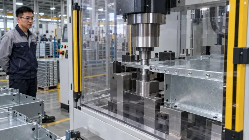
A compound die performs all cuts simultaneously, placing intense mechanical stress on the press. Understanding these physical limits ensures your tooling survives high-volume production without catastrophic failure.
Cutting Force and Load Balance
To size the press correctly, manufacturers calculate the total cutting force for one stroke. For our mounting plate, the outer perimeter plus the four Ø6 mm holes creates a total cutting length of roughly 330 mm. Assuming a material thickness of 1 mm and an estimated shear strength of 400 N/mm² for 304 stainless steel, the baseline cutting force is approximately 132 kN (about 13.5 metric tons).
Suppliers use this baseline to verify press capacity. In practice, to safely absorb the severe reverse load (snap-through) inherent to compound stamping, a manufacturer will typically route this part to a press with at least double the capacity, such as a 30-ton or 45-ton press. They also check for load balance—engineers often stagger the punch lengths so the holes and the perimeter shear milliseconds apart, mitigating peak tonnage.
Die Clearance and Cut Edges

The gap between the punch and the die block is the die clearance. For 1 mm thick 304 stainless steel, a typical per-side clearance is 8% to 10% of the material thickness (0.08 mm to 0.10 mm).
Suppliers rely on trial runs to confirm if this clearance is optimal. If the clearance is too tight, friction spikes and the tool wears rapidly; if too loose, the rollover zone increases and excessive burrs form. Quality inspectors establish separate checkpoints: one for the hole edges (dictated by the punch) and one for the outer blanked edge (dictated by the die cavity).
Part Ejection and Scrap Removal

A compound die must physically expel the finished part before the next stroke. Usually, the four pierced slugs drop through the die block, while a spring-loaded shedder plate pushes the finished 80 × 50 mm plate back up to the die surface, where an air blow-off removes it.
During a trial run, operators watch for two specific failures: whether the finished part clears the tool area in time, and whether the pierced slugs pull back up onto the die surface (slug pulling). Slug pulling can destroy a die, so engineers mitigate it by machining slug retention grooves into the die block. This ejection wait time is why compound stamping often runs at a slower strokes-per-minute (SPM) rate than progressive stamping.
When Does Compound Die Stamping Cost Less?
Lower piece prices only matter if your order volume justifies the upfront investment. Comparing stamping against laser cutting requires a strict break-even analysis based on total cost.
Tooling Cost and Break-Even Quantity
To find the most cost-effective route, compare identical parameters: the same drawing, material, and inspection criteria. The goal is to calculate the precise volume where tooling amortization makes the stamped piece price cheaper than the tool-free laser route.
Assume laser cutting requires zero dedicated tooling and costs $1.50 per piece. The compound die costs $6,000 upfront, but drops the piece price to $0.90. The initial tooling investment pays for itself at exactly 10,000 units.
| Production Volume | Laser Cutting Route ($1.50/pc) | Compound Die Route ($6k Tool + $0.90/pc) | Most Cost-Effective Choice |
|---|---|---|---|
| 5,000 parts | $7,500 | $10,500 | Laser Cutting |
| 10,000 parts | $15,000 | $15,000 | Break-Even Point |
| 20,000 parts | $30,000 | $24,000 | Compound Die |
For orders delivered in split batches, factor in separate machine setup fees and potential die maintenance costs for each production run.
Material Yield and Scrap Value
Piece prices rely heavily on material utilization. Laser cutting software nests the 80 × 50 mm plates tightly across an entire sheet. Stamping requires cutting the material into specific coil widths and leaving a structural web (our 7 mm calculation) between every part to carry the strip.
If the stamping layout reduces material yield and adds $0.10 in net material cost per part (after deducting recyclable scrap value), the stamped piece price increases from 0.90 to 1.00. Consequently, the break-even volume shifts from 10,000 up to 12,000 units (6,000 / (1.50 – $1.00)). Real-world purchasing decisions should substitute these estimates with exact nesting layouts and current raw material quotes.
Secondary Operations and Quote Scope
Before issuing a purchase order, verify exactly what the piece price covers. Compare both quotes to ensure they include necessary secondary operations like deburring, parts washing, flattening, and the agreed-upon inspection reports.
Have the supplier use the first-off trial parts to verify if the as-stamped edges meet your burr limits natively. If mandatory tumbling is added, patch that processing fee back into your comparison table to reflect the true landed cost. Finally, clarify who assumes the cost for routine tool maintenance. Punching 304 stainless steel dulls tool edges rapidly; ensure your $6,000 investment includes routine sharpening for the life of the project without hidden maintenance surcharges.
How Do You Approve the Parts for Production?
Approving a stamped part requires bridging 2D tolerances with shop-floor reality. A structured inspection protocol ensures continuous press operations yield functional components, not just a perfect first sample.
First-Article Inspection
Before releasing a production run, the quality team measures the first off-tool samples against a strict First-Article Inspection (FAI) checklist. For our 80 × 50 mm mounting plate, this involves verifying specific features against defined datums.
| Feature | Requirement | Measurement Method | Datum / Setup |
|---|---|---|---|
| Hole Diameters | Ø6.00 ± 0.05 mm | Pin gauges | N/A |
| Hole Positions | 10.0 ± 0.1 mm | CMM / Optical comparator | Two adjacent locating edges |
| Flatness | Max 0.1 mm deviation | Height gauge on surface plate | Resting on the designated contact face |
| Burr Height | Max 0.05 mm | Micrometer | Checked pre-deburring on the exit side |
Dimensional checks must be paired with functional assembly verification. Operators drop the plate onto the mating part or a custom checking fixture. If the four holes accommodate the fasteners but the plate rocks due to a 0.05 mm burr on the contact face, the part fails FAI. Once FAI is approved, production transitions to standard Acceptable Quality Limit (AQL) sampling for the remainder of the batch.
Trial Run at Production Speed
A single manually triggered stroke does not reflect real-world manufacturing. The supplier must execute a trial run using the actual 1 mm 304 stainless steel coil at the planned production speed (strokes per minute, or SPM).
Operators pull samples during the initial startup and again during stable running to check for thermal drift. As the tool steel heats up under rapid, continuous stamping, die clearances can tighten, affecting edge quality. The process is only approved when dimensions remain stable, tonnage monitors show no force spikes, and both finished plates and scrap slugs eject reliably without jamming the press.
Tool Wear and Reinspection
During ongoing production, operators use visual cues to troubleshoot tool wear. 304 stainless steel is abrasive and work-hardens quickly; even robust tools may require routine sharpening every 30,000 to 50,000 strokes.
If the burr height gradually increases, the cutting edges are dulling. Frequent dulling on high-volume runs justifies upgrading the punch from standard D2 tool steel to a TiCN-coated carbide. If sudden indentations or severe scratches appear on the plate’s surface, a pierced slug has likely failed to drop and was pulled back onto the die face (slug pulling).
Whenever the tool room addresses these issues, targeted reinspection is mandatory. If a Ø6 mm punch is replaced, quality control must reverify the exact hole diameter, its position, and the internal burr. If the outer blanking cavity is ground and sharpened, they must reverify the 80 × 50 mm profile, the 7 mm net edge distance, and the perimeter burr before restarting the press.
Ready to scale your production? Stop guessing whether laser cutting, progressive stamping, or compound die stamping is the most cost-effective route for your current volume. Send your 2D PDFs and 3D CAD (STEP) files to Shengen. Our engineering team will evaluate your edge clearances, calculate your exact tooling break-even quantity, and build a manufacturing routing that minimizes your total landed cost.
Hey, I'm Kevin Lee

For the past 10 years, I’ve been immersed in various forms of sheet metal fabrication, sharing cool insights here from my experiences across diverse workshops.
Get in touch
Kevin Lee
I have over ten years of professional experience in sheet metal fabrication, specializing in laser cutting, bending, welding, and surface treatment techniques. As the Technical Director at Shengen, I am committed to solving complex manufacturing challenges and driving innovation and quality in each project.