Bad sheet metal drawings delay quotes, cause confusion in shops, and result in scrap. Teams lose days sending emails to check bends, hole sizes, and surface finishes. Clear, standard, and complete drawings solve these problems. This guide shows what to include, how to set dimensions, and which notes matter most.
Good sheet metal drawings are the start of smooth production. Let’s look at how to prepare them for the best results.
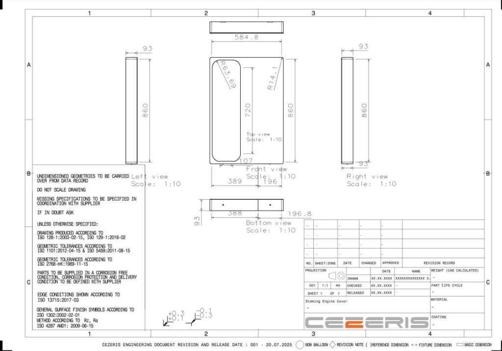
What Are Sheet Metal Drawings?
Sheet metal drawings are technical documents that show a part’s size, shape, and key features. They often list material type, thickness, and finish requirements. Depending on the project, these drawings can be in 2D or 3D. They provide precise cutting, bending, welding, and finishing instructions.
These drawings are the primary reference for every step of fabrication. Engineers use them to choose tooling, plan cutting paths, and decide forming methods. Production teams rely on them to keep work consistent and accurate. Without correct drawings, mistakes can occur at many stages.
Accurate and precise drawings help prevent costly errors and delays. Every measurement and note must be correct. A simple layout with clear symbols makes the information easy to read. Good communication between design and production teams starts with well-prepared drawings.
Types of Sheet Metal Drawings
Different types of sheet metal drawings serve specific roles in design and production. Choosing the right type makes communication clearer and work more accurate.
Concept Drawings for Early Design Stages
Concept drawings present the basic idea of a part or product. They highlight the overall shape, layout, and main features. These drawings are often used in early discussions to collect feedback before moving into detailed design.
Detailed Fabrication Drawings
Detailed fabrication drawings provide exact dimensions, tolerances, materials, and finishes. They also mark bending lines, hole sizes, and welding points. These are the primary references for cutting, forming, and finishing work.
Assembly Drawings for Multi-Part Builds
Assembly drawings show how different parts fit together to make a complete product. They include part numbers, connection points, and fastener details. This helps workers assemble the product in the correct order.
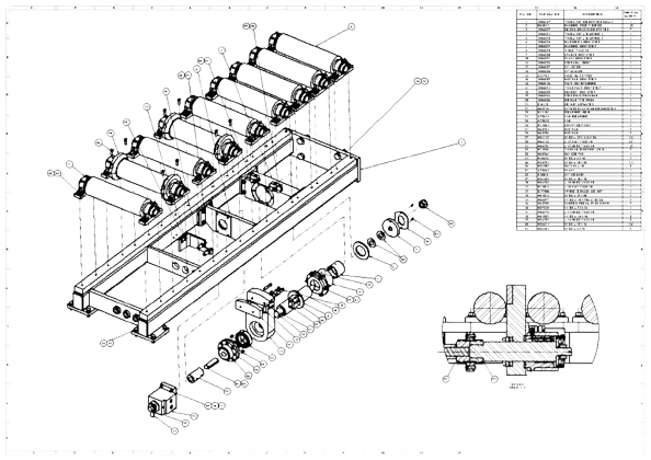
Exploded Views for Complex Builds
Exploded views pull apart each part in space while showing how they connect. They are helpful for complex projects with many components. This view makes the assembly sequence and part identification easier to understand.
Core Elements of a Sheet Metal Drawing
A good sheet metal drawing gives all the details needed for correct production. Each part of the drawing has a clear purpose in guiding the work.
Dimensions and Tolerances
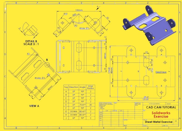
Dimensions show the exact size of every feature. Tolerances explain how much variation is allowed. Smaller tolerances give higher accuracy but can increase production costs.
Bend Lines and Bend Notes
Bend lines show where the sheet will be folded, and bend notes describe the angle, direction, and radius of the bend. Precise bending details help prevent mistakes during forming.
Hole and Slot Specifications
The drawing should list each hole or slot’s size, shape, and position. It should also include any countersinks, counterbores, or thread requirements. Accurate hole details make sure parts fit correctly during assembly.
Material Type and Thickness
The drawing needs to state the exact material and thickness. This affects cutting settings, bending force, and the part’s strength.
Surface Finish Instructions
Surface finish notes explain how the part should look and feel after production. This may include powder coating, anodizing, brushing, or plating. Clear instructions help achieve the proper appearance and long-lasting quality.
Standards and Conventions in Sheet Metal Drawings
Standards and conventions make sheet metal drawings clear and easy to read for different teams and countries. They help keep manufacturing consistent.
Common International Standards (ISO, ANSI, DIN)
ISO, ANSI, and DIN are the most used drawing standards. ISO is common in global projects. ANSI is the standard in the United States. DIN is widely used in Germany. Each standard sets clear rules for dimensions, tolerances, and symbols.
Industry Symbols and Notations
Symbols show processes, features, and finishes without long text. Typical examples are welding symbols, surface roughness marks, and bend direction arrows. Using the correct symbols saves space and reduces misunderstandings.
Units of Measurement and Conversion
Drawings must state whether dimensions are in millimeters or inches. Mixing units can cause costly mistakes, so conversions must be correct. Many companies choose metric for precision, while others use imperial to match existing tools and equipment.
Tools and Software for Creating Sheet Metal Drawings
The right tools and software make creating accurate sheet metal drawings easier and speed up the process from design to production.
CAD Programs for 2D Drafting
2D CAD programs help make flat pattern drawings and simple layouts. They allow designers to show dimensions, bend lines, and other basic details. Popular options include AutoCAD and DraftSight. These programs are straightforward and pleasing for quick edits.
3D Modeling Software with Sheet Metal Modules
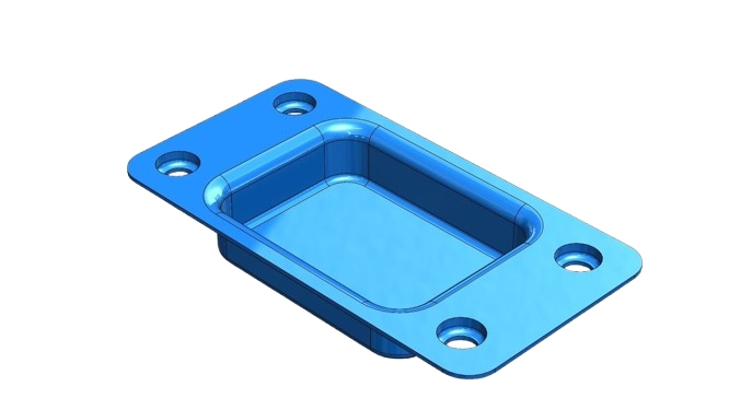
3D modeling software can create detailed models and unfold them into flat patterns. Many have built-in sheet metal modules that add bend allowances, corner reliefs, and accurate material thickness. Programs like SolidWorks, Inventor, and Fusion 360 help visualize the part before production.
Integrating CAM for Production Efficiency
CAM software links the drawing to manufacturing machines. It can generate tool paths for laser cutting, punching, or bending. Integration with CAD saves time and reduces errors because changes in the design update the production files automatically. This leads to faster setup and smoother workflow.
Best Practices for Dimensioning
Good dimensioning makes a drawing clear and easy to follow. It also helps reduce mistakes during fabrication. The way dimensions are placed can affect both speed and accuracy in production.
Placing Dimensions for Readability
Place dimensions outside the main part view whenever possible. Please keep them in line and evenly spaced. Avoid placing them over lines or features that make them hard to see.
Using Datum Points and Reference Edges
Choose clear datum points or reference edges for measurements. These serve as fixed starting points during fabrication. Using consistent references helps keep measurements accurate through all steps.
Avoiding Over-Dimensioning or Conflicts
Only include the dimensions needed to make the part. Too many can create confusion or lead to conflicting values. Give one apparent reference for each measurement to keep the drawing simple and error-free.
Revision Control and Version Management
Reasonable revision control keeps drawings accurate and up to date. It helps avoid mistakes when different teams work from different versions.
Tracking Changes in Drawings
Every change to a drawing should be recorded. This can include changes to dimensions, materials, or processes. A clear history of change makes understanding what was updated and why easier.
Proper Revision Numbering Systems
Use a clear numbering or lettering system for revisions. Many companies start with “Rev A” or “Rev 1” and move to the following letter or number for each change. A simple, consistent system helps teams quickly identify the latest version.
Communicating Updates to Production Teams
Updates should be shared with all production teams. This can be done through printed copies, digital files, or a shared database. Having everyone have the current version reduces errors and rework.
Collaborating Between Designers and Fabricators
Collaboration between design and production teams helps prevent mistakes and speed delivery. Clear communication ensures that the design works well in actual manufacturing.
Sharing CAD Files and Formats
Send CAD files in formats the fabricator’s software can open, such as DXF, DWG, or STEP. When possible, include both 2D and 3D files. This gives the production team a full view of the part and how it should be made.
Getting Feedback from Manufacturing Teams
Ask the fabrication team to review the drawings before production starts. They can spot issues like hard-to-make features, unclear tolerances, or limits with materials. Getting this feedback early saves time and avoids expensive rework.
Design for Manufacturability (DFM) Considerations
Create designs that fit the shop’s capabilities. Avoid excessively tight tolerances, unnecessary bends, or features that need special tools. Keeping designs production-friendly and straightforward lowers costs and shortens lead times.
Conclusion
Sheet metal drawings are the blueprint for accurate and efficient fabrication. They show every detail a manufacturer needs, from dimensions and tolerances to materials and finishes. Precise drawings reduce errors, speed production, and ensure the final product meets requirements.
We can provide expert support from design to production if you need high-quality sheet metal parts made to precise specifications. Contact us today to discuss your project and get a tailored solution.
Hey, I'm Kevin Lee

For the past 10 years, I’ve been immersed in various forms of sheet metal fabrication, sharing cool insights here from my experiences across diverse workshops.
Get in touch

Kevin Lee
I have over ten years of professional experience in sheet metal fabrication, specializing in laser cutting, bending, welding, and surface treatment techniques. As the Technical Director at Shengen, I am committed to solving complex manufacturing challenges and driving innovation and quality in each project.

