Every product that relies on sheet metal parts depends on accuracy. When tolerances are unclear or too loose, parts won’t fit, leading to costly mistakes and delays. Tighter tolerances often mean higher costs, but vague expectations create bigger issues. How can you balance precision and practicality? That’s where precise sheet metal tolerances come in.
Tolerances may seem simple, but they significantly impact nearly every step of sheet metal fabrication. Let’s take a closer look at what they are and how to apply them.
What Are Sheet Metal Tolerances?
Sheet metal tolerances refer to the allowable limits of variation in a part’s size, shape, or feature location. They define how much a measurement can shift from the intended design. Tolerances apply to dimensions such as part length, width, hole size, and bend angles. They help manufacturers determine when a part meets specifications or needs to be remade. Without precise tolerances, parts may not fit or function well.
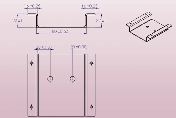
Tolerances are typically represented by “±” values on technical drawings. For instance, a part might be listed as 50 mm ± 0.2 mm, meaning it can be between 49.8 mm and 50.2 mm. These values help manufacturers maintain consistency in their parts. They are set before production and guide the fabrication process.
Why Tolerances Matter in Sheet Metal Fabrication
Tolerances affect how parts are made, fit together, and perform over time. If parts don’t meet tolerance specs, they might not assemble correctly. Or they may wear out faster. Worse, they might fail in the field.
Tighter tolerances need more precise equipment and careful processing. This usually takes more time and money. On the other hand, loose tolerances may reduce cost but could affect the function of the final product.
Setting the proper tolerance is a balance. The goal is to maintain parts within acceptable limits while ensuring cost-effectiveness in production. This is especially true in high-volume production, where even a minor mistake can result in a significant loss.
Who Sets the Standards for Tolerances?
Industry standards usually guide tolerances. In the U.S., many manufacturers follow ANSI or ASME standards. For example, ASME Y14.5 is a common standard for geometric dimensioning and tolerancing (GD&T).
In sheet metal work, many also refer to ISO standards or in-house company guidelines. Sometimes customers specify their tolerances based on the final product’s function.
Core Concepts of Tolerancing
Before applying tolerances, it’s essential to understand what they truly represent. These basic ideas shape how parts are measured and accepted in the production process.
Nominal Dimensions vs. Actual Measurements
A nominal dimension is the ideal target size written on the drawing. It’s what the designer wants the part to be.
The actual measurement is what the part ends up being after it’s made. There is always some variation. No machine can hit the exact number every time. That’s where tolerances come in.
For example, a nominal hole size might be 5.00 mm. After machining, it may measure 5.02 mm. If the tolerance is ±0.05 mm, then the hole is acceptable because it falls within the range of 4.95 mm to 5.05 mm.
Unilateral, Bilateral, and Limit Tolerances
There are different ways to show tolerances:
- Unilateral tolerance allows variation in only one direction. For example, 10.00 mm +0.10/-0.00 means the part can be a little bigger but not smaller.
- Bilateral tolerance allows variation in both directions. For example, 10.00 mm ±0.05 means it can be between 9.95 mm and 10.05 mm.
- Limit tolerance indicates the upper and lower limits directly, such as 9.95 mm – 10.05 mm. This is easier to check during the inspection.
Choosing the right type depends on the part’s function. Some features may need to fit tightly, while others allow more play.
Understanding Geometric Dimensioning and Tolerancing (GD&T)
GD&T is a system that controls shape, orientation, and position—not just size.
It uses special symbols to show how much a part can vary without affecting performance. For example, a hole might need to be round, straight, and centered in a specific zone.
Instead of just saying, “Make this hole 10 mm ±0.1,” GD&T might say, “This hole must stay within this round tolerance zone even if the size varies.”
GD&T is useful when parts must fit together precisely, like in enclosures or moving assemblies. It can make inspection easier and ensure that parts function as they’red.
Types of Sheet Metal Tolerances
Tolerances go beyond just length or width. In sheet metal fabrication, different types help control size, shape, and material behavior. Each type has a clear role in the final part’s performance.
Dimensional Tolerances
Dimensional tolerances control the basic size of the part. They apply to measurements like length, width, height, hole diameter, and slot width.
For example, a flat panel with a nominal width of 100 mm might have a dimensional tolerance of ±0.3 mm. That means any part between 99.7 mm and 100.3 mm is acceptable.
These tolerances are standard in bending, punching, and laser cutting. They help ensure that parts can be assembled or mounted without issues.
Geometric Tolerances
Geometric tolerances control the shape and position of features. They make sure a hole is round, a surface is flat, or a bend is at the right angle.
Standard geometric tolerances include:
- Flatness
- Parallelism
- Perpendicularity
- Position
- Circularity
For example, a flatness tolerance prevents a surface from warping excessively. A position tolerance ensures that holes are in the correct place, allowing fasteners to line up correctly.
These tolerances are crucial when parts must align or move together, such as in enclosures, frames, or hinges.
Material Tolerances
Material tolerances deal with the thickness and surface quality of the raw sheet metal.
Sheet metal thickness can vary slightly across a sheet of metal. For instance, a 1.00 mm stainless steel sheet may have a tolerance of ±0.03 mm depending on the mill standard.
Other material-related tolerances include:
- Surface roughness
- Grain direction
- Coating thickness
Knowing the range of these variations helps during design and inspection. It also affects forming and welding, where consistent thickness and surface are critical.
Standard Tolerance Ranges by Process
Each fabrication method has its typical accuracy range. Knowing what each process can achieve helps you set the right tolerances without overdesigning.
Laser Cutting Tolerances
Laser cutting offers high precision. It works well for complex shapes and tight cuts.
Typical tolerance: ±0.05 mm to ±0.1 mm, depending on material thickness and part size.
Thinner sheets allow tighter control. Thicker materials or long cuts may see more variation due to heat or beam drift. Edge quality is usually smooth, but sharp corners may round slightly on thicker parts.
CNC Punching Tolerances
CNC punching is a fast and efficient method for creating holes and cutouts. Tolerances depend on tool condition and sheet thickness.
Typical tolerance: ±0.2 mm to ±0.4 mm.
Some edge deformation or burrs can occur, especially near hole clusters or edges. For clean holes with tight size control, reaming or laser cutting is often preferred.
Bending and Forming Tolerances
Bending adds complexity. Metal stretches and springs back after forming, making it harder to achieve exact angles.
Typical angle tolerance: ±1°
Typical length tolerance after bending: ±0.25 mm to ±0.8 mm
Material type, thickness, bend radius, and tooling all influence the outcome. Bends that are close to holes or edges require special attention to prevent distortion.
Welding and Assembly Tolerances
Welding generates heat, which can cause parts to warp or alter their dimensions. Even a slight misalignment before welding can result in a poor fit.
Typical tolerance: ±0.5 mm to ±2.0 mm, depending on part size and weld length.
For critical features, fixtures are used to hold parts in place during welding. Post-weld grinding or straightening may be needed for tighter control.
Surface Finishing and Coating Tolerances
Finishing processes add thickness or change dimensions slightly. These need to be considered when parts must fit tightly.
Common finishes:
- Powder coating: adds 20–100 µm
- Anodizing: adds 5–50 µm
- Electroplating: adds 10–30 µm
Tolerances should allow space for the finish layer. If not, parts may not fit after coating. It’s common to machine critical surfaces after finishing or mask them during the process.
Best Practices for Specifying Tolerances
Choosing the proper tolerance helps save time and cost and reduces errors. These tips help keep your designs practical and easier to produce.
Avoid Over-Tolerancing in Designs
Tight tolerances drive up costs. They require slower speeds, more inspections, and precise equipment. If a part doesn’t need tight control, don’t add it.
For example, if a hole is only for airflow, a tolerance of ±0.5 mm might be sufficient. However, if it aligns with a dowel pin, you may need a tolerance of ±0.05 mm.
Set tight tolerances only where they affect fit, function, or safety. Everything else should be looser to speed up production and reduce cost.
Coordinate Early with Fabricators
Consult with your fabrication team before finalizing tolerances. They can tell you what their machines can hold and where you can ease up.
Each shop has different machines, setups, and capabilities. What one factory can do easily might be a challenge for another.
Early input saves time. It avoids redesigns and keeps production moving without surprises.
Use Functional Tolerancing for Critical Features
Focus your tightest tolerances on the features that matter most.
Examples:
- Mounting holes that must align
- Tabs that slide into slots
- Surfaces that form a seal
This approach is called functional tolerancing. It keeps the part working right without over-controlling less critical areas.
Use looser tolerances for cosmetic or non-load-bearing features. This keeps manufacturing flexible and cost-effective.
Document Tolerances Clearly in Drawings
Use consistent symbols and formats. Place tolerances close to the dimensions they apply to.
Avoid vague notes like “all dimensions ±0.1 mm” unless that’s genuinely what you need. Generic tolerances can lead to confusion and increase costs.
For geometric tolerances, use proper GD&T symbols. Include feature control frames, datums, and zones where needed.
Precise drawings help everyone—programmers, machinists, inspectors—know what’s expected. That reduces mistakes and maintains high quality.
Inspection and Quality Control
Inspection ensures that parts remain within specification and maintain consistency from batch to batch. The right tools and checks help catch problems early and reduce waste.
Measuring Tools and Methods
Basic tools are used to quickly and accurately check dimensions.
Common tools include:
- Calipers for external and internal dimensions
- Micrometers for small and precise measurements
- Height gauges and angle finders for flatness and bends
For faster production checks, go/no-go gauges or custom jigs can verify fit without complex setups. These tools are most effective for repeat parts and quick inspections.
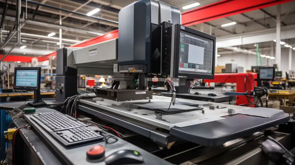
Coordinate Measuring Machine (CMM) Checks
A CMM is used for high-accuracy inspections. It measures part dimensions in 3D using a touch probe or laser.
CMMs are ideal for checking:
- Complex features
- Tight tolerances
- GD&T requirements like position or flatness
CMM data helps confirm that parts meet design intent. It also creates inspection reports for traceability. These are often required in regulated industries or for high-value parts.
First Article Inspection (FAI)
FAI is the detailed check of the first part made in a batch. It confirms that all features meet the drawing before mass production starts.
An FAI report includes:
- Actual measurements of each feature
- Material certs and surface finish checks
- Any deviation or notes
FAI helps catch mistakes early. It gives both the customer and supplier confidence before production runs continue.
In-Process vs. Final Inspection
In-process inspection happens during fabrication. It checks features at key steps—after cutting, bending, or welding. This helps catch problems before they affect the entire part.
The final inspection happens after all work is done. It confirms that the finished part meets all specs and is ready for shipping.
Both are useful. In-process checks reduce rework. Final checks make sure the product is good before it leaves the factory. A mix of both maintains high quality and keeps defects low.
Conclusion
Sheet metal tolerances control the difference between a part’s design and the final product. They help ensure proper fit, function, and quality across every stage of fabrication. Factors like material type, process, and part geometry all affect which tolerances are realistic. Applying the proper tolerance in the right place avoids costly rework and delays.
Need precision sheet metal parts built to your specs? Contact our team for a prompt quote and expert support. We’re ready to help with your next project.
Hey, I'm Kevin Lee

For the past 10 years, I’ve been immersed in various forms of sheet metal fabrication, sharing cool insights here from my experiences across diverse workshops.
Get in touch
Kevin Lee
I have over ten years of professional experience in sheet metal fabrication, specializing in laser cutting, bending, welding, and surface treatment techniques. As the Technical Director at Shengen, I am committed to solving complex manufacturing challenges and driving innovation and quality in each project.


