Electric resistance welding (ERW) is a manufacturing process that fuses metals using localized heat generated by electrical resistance and mechanical pressure. It requires no filler materials or shielding gases, making it a high-speed, cost-effective method for sheet metal assembly and mass production.
While the underlying physics are straightforward, achieving consistent results on the factory floor is a completely different challenge. A poorly controlled ERW process quickly leads to high scrap rates, weak joints, or ruined surface finishes.
Reliable results depend on material selection, joint design, electrode condition, and precise process control. This guide explains how to select the right resistance welding process, design weldable parts, control common defects, and estimate production requirements for your manufacturing projects.
Understand How Resistance Welding Forms the Joint
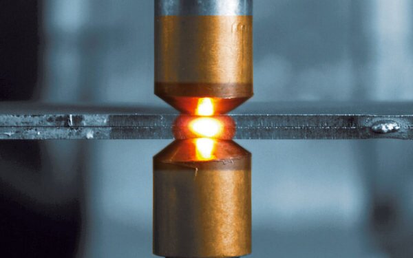
To master resistance welding, you must first grasp the physical forces at play. Current, time, and pressure combine to fuse metals seamlessly without filler materials.
Joule Heating and Electrode Force Mechanics
The core mechanism of resistance welding is Joule heating. When copper electrodes clamp metal sheets together, the natural electrical resistance at the metal interface converts the applied current into heat.
This process follows a basic physical relationship:
Q = I²Rt
In this formula, heat (Q) is determined by current (I), electrical resistance (R), and weld time (t). Because current is squared, it has the largest impact on heat generation. Even minor voltage drops in a factory grid can result in cold welds.
Current and weld time control the total heat input, while electrode force serves a mechanical purpose. The force controls the contact pressure and contains the molten metal. Excessive heat or insufficient electrode force causes expulsion (spatter)—where molten metal blasts out of the joint. Insufficient heat fails to melt the interface completely, creating a weak weld that may fail under load.
Weld Cycle and Nugget Formation
A consistent joint requires a precise mechanical and electrical sequence. The welding machine controller typically manages four main stages for every weld:
- Squeeze time: The electrodes close and apply full mechanical force before the current begins to flow. This ensures stable electrical contact and clamps the parts flat.
- Weld time: Electrical current passes through the sheets, melting the metal at the interface to form a molten pool.
- Hold time: The current stops, but the electrodes maintain full pressure while the molten metal cools and solidifies into a solid weld nugget.
- Off time: The electrodes retract, releasing the part so the operator or robot can index to the next weld location.
Engineering Tip: Releasing electrode pressure before the hold time completes is a leading cause of internal voids and unseen weld cracking.
Choose the Right Resistance Welding Process
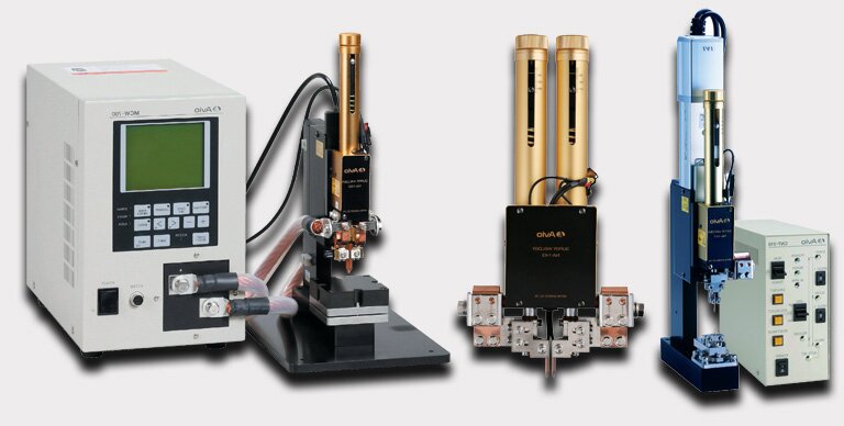
In manufacturing, “electric resistance welding” (ERW) serves as an umbrella term for a family of processes. While high-frequency ERW is widely used in continuous tube and pipe production, most product design and sheet metal assembly rely on spot, seam, and projection welding.
Spot and Seam Welding for Sheet Metal Assemblies
Resistance spot welding is the standard process for repeated lap joints in sheet metal assemblies. It is highly efficient for materials typically ranging from 0.5mm to 3.0mm in thickness per sheet.
Typical applications include:
- Enclosures: Where overlapping sheet metal flanges provide structural rigidity.
- Brackets: For fast assembly without adding the weight of mechanical fasteners.
- Automotive panels: Suitable for high-speed, automated robotic welding.
- Electrical cabinets
- Appliance components
Resistance seam welding operates on the same physical principles but uses rotating copper-alloy wheels instead of point electrodes. As the sheet feeds between the wheels, the machine pulses the current to create a series of overlapping weld nuggets.
Typical applications include:
- Tanks: Where leak-resistant or hermetic seams are required.
- Drums and metal containers
- Thin-wall tubular products
Projection Welding
Unlike spot welding, where the electrode tip defines the weld location, projection welding uses the shape of the part itself to concentrate current and pressure. One of the mating parts features small, raised dimples (projections). When flat electrodes apply force, these projections heat rapidly, collapse, and fuse with the flat mating sheet.
This process allows for multiple weld points in a single machine stroke and reduces visible indentation on the external surface (a major cosmetic advantage). Common applications include:
- Weld nuts and weld studs: Fasteners are supplied with pre-formed projections.
- Crossed wires: Commonly used in wire mesh manufacturing.
- Multiple weld points: For small stamped parts needing simultaneous welds.
- Thick-to-thin joints: Where spot welding would cause severe heat imbalance.
Weld consistency in this process relies heavily on projection shape, precise part location, and rigid fixture accuracy to ensure all projections collapse evenly.
Butt and High-Frequency Welding
Upset butt welding and flash welding are used to join the ends of components rather than overlapping sheets. Typical applications involve wire and rod, rings, structural profiles, and rail components.
High-frequency (HF) contact and induction welding use high-frequency current to heat the edges of a continuous seam. This method is almost exclusively used for continuous tube and pipe production in rolling mills.
| Process | Joint Type |
Typical Application |
Production Volume |
Main Limitation |
|---|---|---|---|---|
| Spot Welding | Lap joint |
Enclosures, brackets |
Medium to High | Leaves visible surface indentations |
| Seam Welding | Continuous lap | Fluid tanks, drums | Medium to High | Limited to straight lines or large radii |
| Projection | Lap or hardware | Weld nuts, wire mesh | High | Requires precise fixturing |
| Butt / Flash | End-to-end | Rods, rings, chain links | Medium to High | Often requires post-weld grinding |
| HF ERW | Continuous seam | Structural steel tube | Very High | Economical only for continuous linear production |
Check Material and Thickness Limits
Every alloy behaves differently under the electrode. Your material choice directly dictates your cycle times, maintenance intervals, and the risk of hidden cold welds.
Low-Carbon and Stainless Steel Alloys
Low-carbon steel (mild steel) is the baseline material for resistance welding. It provides a wide, forgiving parameter window by naturally balancing electrical resistance and thermal conductivity. This results in stable nugget formation and excellent repeatability. For automated production lines, mild steel requires the least amount of process troubleshooting.
Stainless steel behaves differently. Because it possesses higher electrical resistance and lower thermal conductivity than carbon steel, heat concentrates much faster at the joint. While this means stainless requires less welding current, it introduces significant cosmetic challenges. The intense, localized heat often causes heat tint (discoloration) and leaves visible electrode marks.
Galvanized and Coated Sheet Metal
Applying a protective zinc coating to steel fundamentally changes the electrical contact. Zinc melts at a much lower temperature than steel. During the weld cycle, the zinc layer melts first, acting as a conductive bridge that lowers the contact resistance and forces the machine to push more current to achieve the same heat.
For production, coated steels introduce significant maintenance variables, primarily electrode contamination. The molten zinc alloys with the copper electrodes, forming a brass layer on the tip. This causes the electrodes to physically stick to the workpiece and accelerate tip wear, which drops the current density and causes cold welds.
⚠️ Production Note: Welding galvanized steel introduces molten zinc into the copper electrodes. Without automated tip dressing (cutting the electrode face back to its original geometry), cycle times drop and cold welds increase. Always verify that your manufacturing partner accounts for this in their high-volume tooling strategy.
High-Conductivity Metals and Complex Stacks
Metals with high thermal and electrical conductivity actively resist this welding process. The heat dissipates into the surrounding metal before a stable molten pool can form.
- Aluminum: Requires massive current spikes (often 2 to 3 times that of steel), extremely short weld times, and aggressive mechanical or chemical removal of surface oxides prior to welding. It degrades electrodes rapidly.
- Copper: Notoriously difficult to spot weld to itself because heat moves away from the joint instantly. It typically requires specialized refractory electrodes (like tungsten or molybdenum) that generate heat at the electrode face to push into the copper.
When dealing with material stacks, there is no universal “maximum thickness” rule—final limits must be verified by equipment capacity and destructive testing. However, engineers must carefully evaluate thickness ratios (joining a 3.0mm sheet to a 0.5mm sheet is difficult as the thin sheet overheats before the thick sheet melts) and total layer count (welding three or more layers increases the risk of internal voids and inconsistent heat distribution).
Design Parts for Reliable Welding (DFM)
Excellent manufacturing begins on the drafting board. Optimize your part geometry and clearances early to avoid expensive tooling revisions and assembly failures.
Electrode Clearances and Minimum Flange Widths
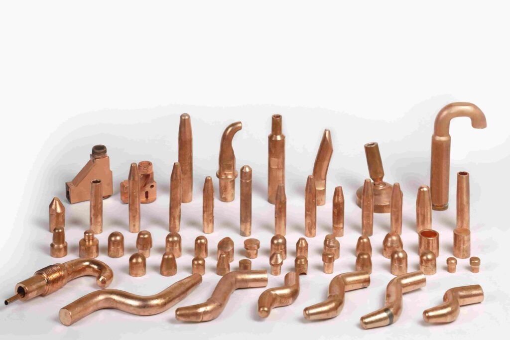
Resistance welding electrodes require unobstructed, perpendicular access to both sides of the joint. If the tooling cannot physically reach the weld location, the part cannot be manufactured.
During the design phase, engineers must verify:
- Approach direction: Are there deep enclosures, ribs, or hardware blocking the electrode shank?
- Nearby bends: Tooling will crash if a weld is placed too close to a vertical wall or bend radius.
- Minimum flange width: The flange must be wide enough to accommodate the full face of the electrode, the expanding weld nugget, the required edge distance, and normal sheet metal folding tolerances.
Shunting Effects, Weld Spacing, and Edge Distances
Placing a weld too close to the edge of a flange causes edge blowout (expulsion). The molten metal lacks enough surrounding solid material to contain it, resulting in severe local deformation, sharp burrs, and weak joint strength.
Equally important is the spacing between multiple welds, driven by a phenomenon called shunting. Electric current takes the path of least resistance. If a new spot weld is placed too close to a previously completed weld, a large portion of the current will “shunt” (divert) through the existing solid weld rather than flowing through the new sheet interface. The result is a cold, undersized nugget at the new location.
While a general guideline like 3 to 4 times the material thickness (3t to 4t) is often cited as a starting point for weld spacing, this is not a universal rule. Actual required spacing is dictated by the target nugget size, material conductivity, electrode diameter, and the programmed welding sequence.
Part Fit-Up and Welded Fastener Integration
A resistance welder is not a press brake; it should not be used to force poorly formed parts together. If there are gaps, springback, or burrs between the mating sheets, the machine wastes its electrode force closing the gap rather than containing the weld. This leads to heavy expulsion, rapid electrode damage, and inconsistent weld strength. Parts must sit flush in the fixture before the electrodes clamp down.
When integrating weld nuts and studs (projection welding), control over the hardware is critical. Engineers must specify:
- Hole position and tolerances: To ensure the fastener seats flat against the sheet.
- Thread protection: Weld spatter can easily ruin internal threads; specify spatter-resistant coatings or masking if necessary.
- Mechanical performance: The final assembly drawings must clearly define the required push-out strength and torque resistance for all welded hardware, which the factory will verify via destructive testing during setup.
Engineering Tip: Always design self-locating features into sheet metal parts (such as tabs and slots) wherever possible. This reduces reliance on expensive custom welding fixtures and prevents parts from shifting under electrode pressure.
Control the Main Welding Parameters
Precision relies on strict control of your machinery’s variables. Balancing current, force, and timing is essential to maintain consistent nugget sizes and joint strength.
Current, Time, and Electrode Force
Process stability relies on balancing three core variables: current, weld time, and electrode force.
Current and time dictate the total heat input. Insufficient heat generation leads to small weld nuggets, incomplete fusion, and “cold welds” that possess little to no mechanical strength. Conversely, excessive heat causes expulsion (where molten metal shoots out from the joint interface), surface burning, protective coating damage, and deep surface indentations.
Electrode force serves a dual purpose. Mechanically, it contains the molten metal pool to prevent expulsion. Electrically, it dictates the contact resistance between the sheets. Higher electrode force presses the microscopic peaks of the metal surfaces closer together, lowering the contact resistance.
Engineering Tip: A common factory error is increasing electrode force to stop expulsion without adjusting the current. Because higher force lowers contact resistance, it decreases the total heat generated, frequently turning an expulsion problem into a hidden cold weld problem.
Electrode Shape, Cooling, and Wear
The physical geometry of the copper electrode dictates the current density (Amps per square millimeter) and the pressure distribution across the joint.
In a high-volume production environment, electrodes degrade continuously. The repeated heat and mechanical pounding cause “mushrooming”—the tip flattens and its contact area enlarges. If the contact area increases by just 20%, the current density drops significantly. The machine will continue to deliver the programmed current, but the dispersed heat will no longer be sufficient to melt the steel, resulting in joint failure.
Stable production requires active heat removal and surface maintenance:
- Cooling-water flow: Chilled water must circulate directly inside the electrode shank to extract heat between cycles.
- Tip dressing: Automated or manual cutting tools must periodically shave the copper tip back to its original geometry to maintain consistent current density.
Welding Windows and Process Monitoring
Relying on a single, fixed machine setting is a risk in mass manufacturing. Production should instead operate within an approved “parameter window” (often mapped as a lobe curve) that accounts for normal fluctuations in material thickness, factory voltage, and tool wear.
A standard welding schedule must explicitly define:
- Allowable current and force ranges
- Weld and hold times
- Electrode alloy and tip geometry specifications
- Mandatory tip dressing intervals
Modern manufacturing relies on in-process monitoring rather than just post-weld inspection. By tracking actual current delivery, electrode displacement (how much the metal compresses as it melts), and dynamic resistance curves in real-time, process controllers can detect electrode wear, surface contamination, or missing parts before a defective batch is produced.
Prevent Defects and Verify Weld Quality
Visual checks are never enough to guarantee structural integrity. Implement rigorous testing and monitoring to catch hidden defects before parts reach your customers.
Cold Welds and Small Nuggets
Cold welds are the most dangerous defect in sheet metal assembly because the joint appears fully formed on the outside but lacks internal fusion.
Common causes include low current, worn (mushroomed) electrode tips, heavy surface contamination (like oil or heavy mill scale), and current shunting through adjacent welds. Because a cold weld leaves a normal-looking indentation on the metal surface, visual inspection cannot reliably identify it. Detecting cold welds requires strict adherence to destructive testing schedules and in-process current monitoring.
Expulsion, Indentation, and Electrode Sticking
Expulsion is a visible indicator of process instability. It is primarily caused by excessive current, delayed hold times, low electrode force, or poor sheet fit-up that prevents the electrodes from properly containing the molten pool.
Visible expulsion does not mean the weld is stronger; in fact, the loss of metal often results in deep electrode marks, severe assembly distortion, and a weaker overall joint. For coated materials like galvanized steel, excessive heat also causes the zinc to alloy with the copper tip, leading to severe electrode sticking and part deformation upon release.
| Defect | Primary Cause | First Corrective Action |
|---|---|---|
| Cold Weld / No Fusion | Insufficient current density | Check tip for mushrooming; dress tip or increase current. |
| Heavy Expulsion | Force too low or current too high | Increase electrode force; verify parts sit flat in fixture. |
| Deep Indentation | Excessive heat or excessive force | Decrease current/weld time; verify correct tip diameter. |
| Electrode Sticking | Coating buildup (brass formation) | Implement tip dressing; optimize cooling water flow. |
| Edge Blowout | Weld placed too close to flange edge | Adjust weld location or increase flange width. |
Inspection, Testing, and Production Approval
Quality verification occurs in two phases: pre-production setup and in-process monitoring.
Destructive Testing (Setup & Verification):
Before a production run begins, the welding schedule must be validated through destructive methods.
- Peel and Chisel Tests: Physically tearing the welded sheets apart. A successful weld will pull a “button” of solid metal out of one sheet, proving the weld is stronger than the base material.
- Tensile Shear and Push-Out Tests: Laboratory tests used to verify that the joint meets the precise load requirements defined in the engineering drawings.
- Metallographic Cross-Sections: Cutting and etching the weld to inspect internal nugget diameter and check for micro-cracking.
Non-Destructive & In-Process Inspection:
During mass production, operators rely on visual inspection to catch part deformation, severe indentation, or surface burning. Simultaneously, automated ultrasonic inspection or dynamic resistance analysis monitors the internal integrity of the joint without destroying the final assembly.
Transparency is key to international supply chains. We provide complete metallurgical cross-section reports and destructive test logs alongside our initial sample shipments, ensuring engineering teams across the globe have verifiable proof of joint integrity before authorizing mass production.
Conclusion
Electric resistance welding is just one piece of the puzzle. Whether you are transitioning a custom sheet metal enclosure from rapid prototyping directly into mass manufacturing, or integrating CNC machined components with welded assemblies, success requires a fabrication partner who understands the mechanical realities of the factory floor.
Every engineering decision—from selecting the right alloy to respecting minimum flange widths—directly impacts final production costs, assembly speed, and joint integrity. Do not let poor fit-up or process instability delay your supply chain.
Ready to move your project into production?
Submit your STEP files or technical drawings to Shengen today for a comprehensive Design for Manufacturability (DFM) review. We will evaluate your designs for weldability, tolerance stack-ups, and cost-efficiency to ensure a seamless transition from concept to finished assembly.
Hey, I'm Kevin Lee

For the past 10 years, I’ve been immersed in various forms of sheet metal fabrication, sharing cool insights here from my experiences across diverse workshops.
Get in touch
Kevin Lee
I have over ten years of professional experience in sheet metal fabrication, specializing in laser cutting, bending, welding, and surface treatment techniques. As the Technical Director at Shengen, I am committed to solving complex manufacturing challenges and driving innovation and quality in each project.