Getting precise bends in sheet metal can make or break your project. Bend allowance impacts part dimensions, material use, and assembly. This guide will help you see what bend allowance is, why it matters, and how you can use it for better results.
To clearly understand how bend allowance works, we need to look at the key factors that influence it. We also need to review simple ways to calculate it. Finally, let’s go over a few practical examples. This will help us make accurate bends every time.
What is Bend Allowance in Sheet Metal Fabrication?
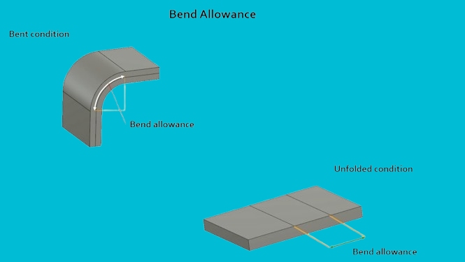
Bend allowance is the curved length of metal between the bend lines. It tells you how much material is needed in the bend area. When metal bends, it stretches slightly on the outer side and compresses on the inner side. The bend allowance measures that change.
The allowance depends on factors like material type, thickness, bend angle, and inside radius. Each bend in a part adds length, and ignoring that leads to wrong sizes. By calculating the bend allowance, you can adjust the flat pattern before bending. This helps make sure the finished part comes out right.
The Science Behind Bend Allowance
To bend sheet metal accurately, you need to know what happens inside the material. These changes affect the shape, length, and fit of the final part.
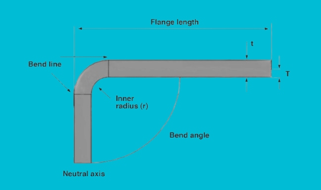
Bend Line and Neutral Axis Explained
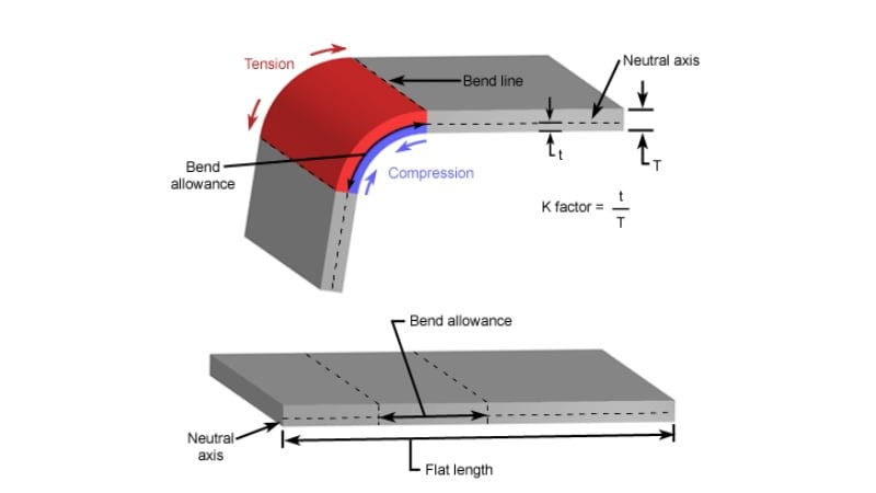
The bend line marks the start of the bend. On one side of this line, metal compresses. On the other side, it stretches. Between the two is the neutral axis. This line stays the same length, even as the metal bends.
For most bends, the neutral axis shifts toward the inside of the bend. It’s not centered. For example, in a 90° bend on 1.0 mm thick steel, the neutral axis often sits about 0.4 mm from the inner surface. That value changes with material type and bend radius.
K-Factor and Its Role in Calculating Bend Allowance
The K-Factor defines where the neutral axis lies. It’s calculated using this formula:
K = t / T
- t = distance from the inner surface to the neutral axis
- T = material thickness
Common K-Factor values:
- Soft aluminum (5052-H32): 0.33 to 0.42
- Cold rolled steel (SPCC): 0.40 to 0.50
- Stainless steel (304): 0.45 to 0.50
- Titanium Grade 2: 0.30 to 0.35
Let’s say you’re working with 2 mm thick cold rolled steel, and your measured K-Factor is 0.45. The neutral axis sits 0.9 mm from the inner surface. That data helps ensure your flat pattern length calculation stays accurate.
Key Factors Influencing Bend Allowance
Several factors affect how much material is needed for a bend. Each one changes how metal stretches and compresses during forming.
Material Type and Its Impact
Different metals stretch in various ways. Softer materials like aluminum bend more easily and require less force. Harder metals like stainless steel need more force and may spring back more after bending.
For example, aluminum 5052 bends easily and often uses a lower bend allowance. Stainless steel 304 resists bending more and requires a larger bend radius to avoid cracking. Material ductility and tensile strength are key to how it reacts under pressure.
If you’re bending high-carbon steel, you’ll need to add more allowance to avoid over-bending or part distortion. Always consider the metal’s mechanical properties.
Thickness of the Metal Sheet
Thicker sheets stretch more during bending. As thickness increases, the bend area becomes longer. This means a higher bend allowance is needed.
For instance, a 3 mm thick steel sheet bent at 90° will require a longer bend allowance than a 1 mm sheet at the same angle and radius. Here’s a general rule: as thickness goes up, so does bend allowance.
A thicker sheet also shifts the neutral axis further from the inner surface. That directly affects the K-Factor and makes the flat pattern longer. Always measure or calculate based on actual thickness.
Bend Radius and Its Significance
The bend radius is the inside curve of the bend. A small radius stretches the outer surface more, which increases the bend allowance. A larger radius causes less stretching and needs less allowance.
For example, bending 1.5 mm steel with a 1.5 mm radius will need more bend allowance than bending the same sheet with a 3 mm radius. Small radii risk cracking, especially in hard materials.
A good practice is to match the bend radius to the sheet thickness. For mild steel, a radius equal to material thickness (1T) is usually safe. For aluminum, you can often go smaller, but for stainless steel, consider using a radius of 1.5T or more.
Angle of Bend and How It Affects Allowance
The bend angle is how far the sheet is bent, measured in degrees. The sharper the angle, the more the metal stretches. This means larger bend angles need more allowance.
A 90° bend requires more material in the bend zone than a 45° bend. A 135° bend stretches even more and needs a longer flat layout. Here’s a quick comparison using a 1 mm steel sheet with a 1 mm radius:
- 45° bend ≈ 1.1 mm allowance
- 90° bend ≈ 1.6 mm allowance
- 135° bend ≈ 2.4 mm allowance
The higher the angle, the more the flat pattern must compensate for material stretch.
Bend Allowance Formulas and Calculations
To create an accurate flat pattern, you need to calculate bend allowance correctly. This section shows how to do it step by step.
Introduction to the Bend Allowance Formula
The most widely used formula for bend allowance is:
BA = (π × A × (R + K × T)) / 180
Where:
- BA = Bend Allowance
- π = 3.1416
- A = Bend angle in degrees
- R = Inside bend radius
- T = Material thickness
- K = K-Factor (depends on material and bend setup)
This formula gives the arc length of the neutral axis, which is what you add to the flat length to get accurate results.
Step-by-Step Calculation Process
Let’s walk through an example.
Material: Aluminum 5052-H32
Thickness (T): 2 mm
Inside Radius (R): 2 mm
Bend Angle (A): 90°
K-Factor: 0.38
Step 1: Plug values into the formula
BA = (3.1416 × 90 × (2 + 0.38 × 2)) / 180
Step 2: Calculate the neutral axis term
2 + (0.38 × 2) = 2.76
Step 3: Multiply
3.1416 × 90 × 2.76 = 779.06
Step 4: Divide
779.06 / 180 = 4.33 mm
The bend allowance is 4.33 mm. You add this to your flat pattern to account for bending.
Common Mistakes to Avoid in Calculations
- Wrong K-Factor: Using a general guess can lead to size issues. Always use tested or recommended values for your specific material and setup.
- Ignoring actual thickness: If your sheet is coated or mismeasured, even a slight difference affects the result.
- Incorrect radius: Using tooling radius instead of actual bend radius can lead to errors. Measure the formed bend if unsure.
- Confusing bend angle: Always measure the included angle. Don’t mix up inside and outside angles.
- Not rounding the result: Use one decimal place when rounding bend allowance. Too many or too few can create inconsistencies in production.
Bend Allowance Calculator
Bend Allowance vs. Bend Deduction
These two methods help you plan the flat length for a bent part. Both are useful, but they are used in different ways.
Key Differences and When to Use Each
Bend Allowance (BA) is the arc length of the bend, measured along the neutral axis. You add it to the total flat length. It’s used when you know the bend angle, radius, and K-Factor.
Bend Deduction (BD) is the amount you subtract from the total flange lengths to get the flat pattern. It’s based on the same bend, but it uses outside measurements.
Use Bend Allowance when you calculate from the inside of the bend or when you want to work from known radius and material values. It gives you more control in CAD or CNC software.
Use Bend Deduction when you measure the part from outside to outside, especially in manual layouts or simple flat pattern drawings. It’s often used in press brake operations where flange lengths are known.
Both lead to the same flat length in the end, just from different starting points.
How to Convert Between Bend Allowance and Bend Deduction?
You can convert between Bend Allowance and Bend Deduction using this formula:
BD = FL1 + FL2 – BA – Total Flat Length
But for most use cases, this simpler version is used:
BD = FL1 + FL2 – Flat Length
Or, more commonly:
Flat Length = FL1 + FL2 – BD
Where:
- FL1 and FL2 are flange lengths
- BD is the bend deduction.
- BA is the bend allowance.
Here’s a quick example:
- FL1 = 30 mm
- FL2 = 40 mm
- BA = 4.33 mm
Then:
Flat Length = 30 + 40 – Bend Deduction
or
Flat Length = 30 + 40 + BA – 2 × Outside Setback
The choice between BA and BD depends on how you measure and design your parts. Use whichever fits your tooling setup or CAD process.
Best Practices for Optimal Bend Allowance
Getting the bend allowance right improves fit, reduces scrap, and makes production smoother. Here are ways to keep your bends accurate and repeatable.
Tips for Consistent and Accurate Bending
- Use the same tools: Stick with the same punch and die set across production. Changing tooling affects the bend radius and results.
- Set standard K-Factors: Use tested K-Factors for each material and thickness. For example, use 0.38 for aluminum 5052 and 0.44 for mild steel.
- Bend perpendicular to grain: Bending along the grain increases cracking. Go across the grain whenever possible.
- Avoid sharp radii: Use a bend radius equal to at least 1x material thickness for clean results unless the design requires otherwise.
- Keep tooling clean: Dirt and worn tools create inconsistent bends.
- Control spring back: Use bottoming or coining for high-precision parts where springback must be minimal.
How to Validate Your Bend Allowance Calculations?
- Make test bends: Cut a short strip and perform a bend. Measure the actual result, then compare it to your flat layout. Adjust the K-Factor if needed.
- Check against CAD output: Use the calculated flat length to create a CAD drawing. Bend a sample and match it to the CAD part.
- Measure the neutral axis manually: Use calipers to measure from the inner bend to the centerline of the bend arc. Calculate the actual K-Factor and update your formulas.
- Track repeat jobs: Keep records of bend results for repeat parts. Use this data to fine-tune future calculations.
- The review formed part tolerances: If hole positions or flange lengths are off, it may point to the wrong bend allowance. Adjust accordingly.
Following a few repeatable steps helps reduce trial and error. Once you dial in your setup, the results stay reliable across batches.
Conclusion
Bend allowance is the added length in the flat pattern to account for the material stretch during bending. It helps ensure your finished part has the correct size and shape. Factors like material type, thickness, bend angle, bend radius, and the K-Factor all affect the allowance.
Need help with accurate sheet metal bending or prototyping? Our engineers are ready to support your next project. Contact us to get a free consultation or quote.
Hey, I'm Kevin Lee

For the past 10 years, I’ve been immersed in various forms of sheet metal fabrication, sharing cool insights here from my experiences across diverse workshops.
Get in touch
Kevin Lee
I have over ten years of professional experience in sheet metal fabrication, specializing in laser cutting, bending, welding, and surface treatment techniques. As the Technical Director at Shengen, I am committed to solving complex manufacturing challenges and driving innovation and quality in each project.
Related Resource

Fingerprint Resistant Stainless Steel: How It Works,and How to Choose


