In many factories, robots spend more time correcting misaligned parts than assembling them. Automation only performs as well as the parts it handles. A well-designed metal part enables faster cycles, smoother robotic motion, and fewer operator adjustments. Poor design introduces misfeeds, downtime, and costly manual fixes.
This article explains how engineers can design automation-ready sheet metal parts that transition efficiently from CAD to mass production, balancing precision, manufacturability, and robotic compatibility.
Design Goals for Automation-Friendly Metal Parts
Intelligent automation starts with clear design intent. These core principles ensure every part of your robot’s handling behaves predictably, reducing misalignment and cycle interruptions.
Consistency and Repeatability Over Complexity
Automated systems rely on repetition. A robotic press or gripper performs identical motions thousands of times, expecting each part to match the last. Even minor variation—uneven bend radii, irregular holes, or inconsistent flange width—can interrupt feeding or trigger quality stops.
Key Practices
- Use standardized hole diameters (4 mm, 6 mm, and 8 mm) that are compatible with automated punching and riveting tools.
- Maintain uniform sheet thickness to prevent fixture misalignment.
- Define clear primary datums for robotic positioning and inspection systems to ensure accurate positioning and inspection.
In high-speed assembly lines, even a ± 0.1 mm variation can trigger feeder faults that require manual resets—costing 3–5 minutes per stop. Consistent geometry maintains steady cycle times and improves yield.
💡 Design Tip: Keep hole-to-edge spacing uniform across mirrored parts. Robots use these distances for auto-alignment during pick-and-place operations.
Simplify for Handling and Assembly
Every robot relies on geometry that can be gripped and oriented consistently, every time. Irregular contours, fragile tabs, or offset holes confuse vision sensors and cause misfeeds.
A good rule: Design for one obvious orientation—so the machine always “knows” how to pick it.
- Avoid narrow or nested shapes that may tangle in feeders.
- Add simple orientation cues such as flat reference edges or symmetrical corners.
- Replace sharp transitions with gradual radii to support smooth gripper contact.
Simplified geometry improves throughput. Studies show that streamlining part profiles can reduce feeding errors by 30–40 % and enhance throughput stability across multi-shift operations.
⚠️ Common Mistake: Designing decorative cutouts that vary between left- and right-hand parts. Vision systems treat them as different models, doubling programming effort.
Design for Modularity and Maintenance
Automated systems favor modular designs that are easy to assemble, test, and replace. If every repair requires complete disassembly, downtime and labor costs multiply quickly.
Modularity offers several automation benefits:
- Parallel assembly: Sub-modules can be fabricated and tested on separate stations.
- Faster maintenance: Replaceable modules reduce repair time by 20–30%.
- Future scalability: Upgraded modules can reuse mounting interfaces without requiring a redesign of the entire frame.
Standardized hardware—such as self-clinching nuts, quick-release panels, and mounting tabs—helps both robots and technicians assemble or service products without the need for custom tools.
💡 Design Tip: Use identical fastener types across all sub-assemblies. Automated screwdrivers and feeders operate faster when hardware is standardized.
Material and Process Selection
Even flawless geometry fails without stable materials and consistent fabrication. Choosing the right alloy and process lays the foundation for automation reliability.
Matching Material to Function and Process
Automation requires materials that form, bend, and weld without unexpected deformation. Each metal behaves differently when exposed to heat, pressure, and tooling stress, so the choice affects both speed and reliability.
Standard Materials for Automated Fabrication:
- Cold-Rolled Steel (CRS): Offers stable strength and a smooth finish, making it ideal for automated stamping and bending lines.
- Stainless Steel 304/316: Resistant to corrosion and surface oxidation; performs well in cleanroom or outdoor automation systems.
- Aluminum 5052/6061: Lightweight, with good ductility for robotic bending; reduces tool wear and enables faster forming cycles.
- Copper and Brass: Excellent for conductive components, but require lower feed pressure and careful clamping due to softness.
Uniformity matters as much as type. Maintaining a ±0.05 mm thickness tolerance across batches can reduce rework rates by 20–30%, as consistent material thickness helps CNC tools and sensors calibrate more reliably.
💡 Design Tip: Choose materials with consistent coil flatness (≤ 2 mm deviation per meter). Uneven sheets cause gripper slip and tool misalignment in robotic feeders.
Fabrication Methods That Support Automation
Automated lines rely on processes that minimize variation and eliminate the need for human adjustment. Choosing the proper fabrication sequence allows machines to maintain precision across shifts without constant recalibration.
Automation-Compatible Fabrication Processes:
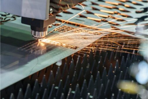
- Laser Cutting: Delivers tight tolerances (± 0.05 mm) and smooth edges that require no deburring. Fiber lasers can process at a rate of 100+ m/min in continuous operation with negligible variation.
- CNC Punching: Ideal for repetitive hole patterns; automated tool changers support mixed geometries with minimal downtime.
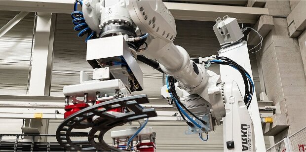
- Robotic Bending: Advanced press brakes equipped with angle sensors maintain ±0.2 ° accuracy, ensuring precise alignment across hundreds of parts.
- Robotic Welding: Produces uniform bead width and penetration depth, reducing inspection and rework cycles by up to 25 %.
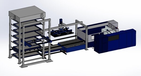
At Shengen, our production teams often recommend a hybrid setup—laser cutting for profile accuracy, robotic bending for repeatable forming, and CNC welding for consistency—especially for enclosures, frames, and bracket assemblies.
This combination ensures predictable cycle times and stable part geometry throughout 24/7 automated operation.
⚠️ Common Mistake: Designing parts that require multiple re-clamping steps between cutting and bending. Each manual transfer introduces a misalignment risk and slows automation by 15–20%.
Surface Finish and Post-Processing
A smooth, consistent surface allows grippers, conveyors, and sensors to perform accurately. Surface defects or inconsistent coatings can interfere with part detection or automated assembly alignment.
Popular Finishing Options for Automated Parts:
- Powder Coating: Strong, uniform coverage; designers should compensate for coating buildup (~ 0.08–0.12 mm per side) when defining hole and slot tolerances.
- Anodizing: Ideal for aluminum parts, providing both corrosion protection and stable surface friction for robotic gripping.
- Zinc Plating / E-Coating: Useful for conductive assemblies requiring EMI/RFI grounding continuity.
- Bead Blasting / Brushing: Creates consistent textures, improving visual inspection and optical sensor recognition.
Controlled tests have shown that maintaining a uniform surface finish reduces robotic vision errors by 15–20% and prevents false rejects during inspection. The finishing process is not just about aesthetics—it’s part of your automation quality strategy.
💡 Design Tip: When using reflective finishes (like polished stainless or chrome plating), add matte reference zones or fiducial marks for machine-vision detection.
Design Features That Improve Automated Assembly
Minor design tweaks create significant efficiency gains. These assembly-oriented details enable robots to work smoothly with minimal fixture adjustments.
Hole, Slot, and Tab Optimization
Holes and slots are more than functional—they define how easily machines can locate, grip, and align parts.
A poorly placed hole can break a production rhythm. Well-designed hole and slot systems improve repeatability and reduce fixture dependency.
Design Principles for Automation-Friendly Features:
- Maintain edge distances of 1.5–2.0 times the material thickness to prevent cracking during the forming process.
- Use standardized diameters (4, 6, and 8 mm) that are compatible with automated insertion tools.
- Align holes along typical datums for fast robotic orientation.
- Maintain uniform slot width to allow tolerance absorption during assembly.
💡 Design Tip: When adding alignment tabs, position them at symmetrical points. Robots use geometric balance to determine part orientation faster.
Self-locating features, such as tab-and-slot assemblies, can reduce fixture requirements by up to 35%, allowing robots to perform both alignment and joining in a single pass. For thin-gauge sheet metal frames, this design approach often eliminates the need for secondary jigs.
⚠️ Common Mistake: Using decorative or non-standard cutouts for alignment. Machine vision systems struggle to detect irregular shapes, which slows down cycle times.
Tolerances and Datum Control
Tolerances determine how reliably parts fit and how smoothly automation repeats that fit thousands of times.
Too tight, and parts jam or deform; too loose, and they rattle under vibration or fail inspection.
Best Practices for Automated Tolerance Planning:
- Define clear primary, secondary, and tertiary datums for positioning, bending, and joining.
- Avoid unnecessary tolerances of ±0.05 mm unless critical; ±0.1–0.2 mm is often adequate for robotic welding or bending.
- Simulate tolerance stack-up in CAD to predict cumulative error before production.
In robotic assembly studies, maintaining consistent datum schemes can reduce fixture setup time by 20–25 % and improve pass rates during first-article inspection.
💡 Design Tip: For parts assembled by dual-arm robots, align key datums along both axes to simplify calibration and reduce vision correction loops.
Fastener and Joint Selection
Choosing the proper joining method can dramatically improve automation throughput. Manual fastening steps slow production, while automation-friendly joints maintain consistent cycle timing.
Recommended Fastening and Joining Methods:
- Self-Clinching Fasteners (PEM/Rivet Nuts): Ideal for robotic pressing, eliminating torque variation and providing repeatable pull-out strength.
- Spot/Seam Welding: Consistent electrical contact ensures identical weld beads, providing stable joint penetration and integrity.
- Tab-and-Slot Joints: Allow for fast mechanical alignment, often eliminating the need for separate locating fixtures.
- Snap-Fit or Latch Systems: Suitable for light-duty covers or panels where fast assembly outweighs load-bearing needs.
In high-volume manufacturing, automated fastener insertion systems can process 1,000–1,200 components per hour with < 1 % deviation. Standardizing hardware types—using the same screw length, thread, and head style—further reduces tool change time and programming effort.
⚙️ Shengen Insight: In our production lines, switching from manual nut welding to robotic PEM insertion reduced total assembly time by 42 % and eliminated post-weld distortion issues.
Integrating Automation from Prototype to Production
Design validation bridges concept and scale. These steps turn a working prototype into a stable, high-volume automated process.
Early DFM and Simulation
Good automation starts with early validation. A DFM review highlights forming limits, tool reach, and tolerance stack-up before a single sheet is cut. Virtual simulations also confirm robotic motion paths, bending angles, and weld accessibility long before physical trials begin.
Best Practices for DFM Validation
- Simulate bending and springback angles to confirm forming stability.
- Validate robotic welding paths for clearance and access.
- Run digital pick-and-place simulations to detect orientation issues.
Early simulation saves real money. Factories that utilize DFM validation reduce engineering change orders by 30–50% and accelerate production readiness by 20–30%.
💡 Design Tip: Run a quick DFM check before finalizing CAD. Fixing a bend radius digitally costs minutes—fixing it after tooling costs weeks.
Prototype Runs to Validate Automated Steps
Even with simulation, a physical prototype tells the truth. Small pilot batches enable engineers to verify bending accuracy, alignment fit, and the real-world performance of materials. This phase exposes distortion, feed issues, or gripping inconsistencies that digital models may miss.
Prototype Run Objectives
- Verify hole distortion, springback, and weld quality.
- Confirm fixture alignment and assembly orientation.
- Collect statistical data for robotic calibration and repeatability.
Validated prototypes typically reduce scrap by 30–40% in later stages. At Shengen, pilot runs are standard before automation ramp-up—our engineers use live process data to fine-tune forming angles and feeding pressure, achieving smoother transitions into mass production.
⚠️ Common Mistake: Skipping prototype verification to “save time.” The first production batch then becomes the test—and often the most expensive lesson to learn.
Scalable Tooling and Fixture Design
Flexible tooling is the foundation of scalable automation. Static jigs are suitable for one part; modular fixtures, on the other hand, adapt to product revisions and mixed-model production without requiring significant downtime.
Scalable Tooling Guidelines
- Use interchangeable locator pins and plates for different models.
- Integrate quick-change clamps to reduce setup time.
- Standardize fixture interfaces for both robotic and manual operations to ensure consistency and efficiency.
These strategies shorten changeovers and improve machine utilization. In mixed-production environments, flexible fixtures can improve line efficiency by 25–35 % while maintaining consistent quality.
💡 Design Tip: Plan fixture holes and datum pads during the design phase. Retrofitting fixture compatibility later often doubles tooling cost.
Balancing Cost, Speed, and Flexibility
Automation must serve your production goals—not control them. It’s most cost-effective when applied to repeatable, stable parts and scalable volumes. For high-mix, low-volume projects, semi-automated lines (combining manual loading with robotic bending/welding) often deliver the best balance of speed and investment.
ROI Guidelines
- Full automation: For stable, long-term, high-volume parts.
- Semi-automation: For flexible or prototype builds.
- Hybrid automation: Combines manual oversight with automated precision for small batches.
Building a standardized component library—standard brackets, PEM inserts, hole patterns—helps reuse proven designs across product lines. This consistency can reduce design lead time by up to 40% while simplifying automation programming.
Conclusion
Automation success isn’t about replacing people—it’s about designing more intelligent systems. When engineers plan for consistency, verify through simulation, and validate with pilot runs, automation becomes a strategic advantage rather than a risk.
If you’re developing automated machinery, robotic systems, or precision metal assemblies, our engineers can assist you in designing and validating automation-ready components. Contact Shengen today to optimize your next project for automated manufacturing efficiency.
FAQs
What makes a metal part “automation-ready”?
An automation-ready part has consistent geometry, explicit datum references, and standardized features for robotic gripping, orientation, and assembly.
How can DFM improve automated production?
Early DFM reviews detect geometry risks, formability issues, and tolerance stack-ups before tooling starts—reducing rework by 30–50%.
Which materials perform best in automated fabrication?
Cold-rolled steel, stainless steel 304/316, and aluminum 5052 are commonly used due to their stable forming properties, corrosion resistance, and predictable bend performance.
What surface finishes are suitable for use in automated environments?
Powder coating, anodizing, and zinc plating offer consistent surfaces for robotic handling. Designers should account for coating buildup (≈ 0.1 mm per side).
What fasteners and joints work best for robotics?
Self-clinching nuts, tab-and-slot joints, and spot welds allow automated assembly with repeatable torque and alignment.
Hey, I'm Kevin Lee

For the past 10 years, I’ve been immersed in various forms of sheet metal fabrication, sharing cool insights here from my experiences across diverse workshops.
Get in touch
Kevin Lee
I have over ten years of professional experience in sheet metal fabrication, specializing in laser cutting, bending, welding, and surface treatment techniques. As the Technical Director at Shengen, I am committed to solving complex manufacturing challenges and driving innovation and quality in each project.
Related Resource

Fingerprint Resistant Stainless Steel: How It Works,and How to Choose


