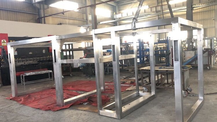
A stable machine frame protects accuracy from day one. When the base does not shift under load, the entire machine operates with smoother motion and tighter repeatability. This is why frame stiffness, load control, and long-term durability matter as much as the components mounted on it.
Sheet metal and tubular structures provide strong stiffness-to-weight performance. Closed profiles and bent sections often outperform bulky solid plates. With proper geometry, frames stay rigid even with moderate thicknesses such as 2–6 mm steel or 3–5 mm aluminum. The goal is to provide the machine with a structure that remains stable during vibration, thermal fluctuations, and continuous operation.
This section explains how geometry, load paths, and material choices shape a frame’s stiffness. These early decisions create the foundation that later stages—such as connections, fabrication, and inspection—must support.
Frame Design Fundamentals
A rigid frame begins with good geometry and clear load paths. The points below illustrate how structure, material, and reinforcement collectively influence overall stability.
Load Paths and Structural Geometry
Strong frames use closed shapes, short spans, and balanced layouts. Box sections and tubes resist bending far better than open channels. Tests on thin-walled structures show that enclosed profiles can be 2–4× stiffer than open ones under the same load. This advantage makes boxed corners and tubular members ordinary in equipment frames.
Common design traps include long unsupported panels, tall narrow frames, and sharp internal corners. These areas experience higher deflection and stress concentration. Small changes, such as adding a rib, folding an edge, or widening the base, can reduce deflection by 20–40%. Early geometry corrections prevent twist, racking, and vibration problems later in the machine’s life.
Material Selection for Rigidity and Strength
Material stiffness controls how much the frame bends. Steel has a modulus of approximately 200 GPa, while aluminum offers a modulus of about 69 GPa; therefore, aluminum requires more thickness or additional ribs to match the stiffness of steel. Each choice affects weight, cost, vibration behavior, and weld distortion.
Thickness also shapes stiffness. Bending resistance increases with thickness cubed. A 3 mm plate can be more than twice as stiff as a 2 mm plate, even though its weight rises by about 50%. Thicker parts, however, create more welding distortion and demand stronger fixtures during fabrication.
Tubular materials help balance performance. A 40×40×2 mm steel tube often carries bending loads more efficiently than a solid 10 mm plate of similar width. This allows higher rigidity without unnecessary mass.
Stiffness Optimization Techniques
Reinforcement features strengthen weak points before they create alignment issues. Gussets increase corner strength. Cross-members reduce the bending of long spans. Internal ribs stop wide sheet-metal panels from oil-canning or vibrating.
Closed shapes deliver the highest stiffness gains. A simple U-channel becomes a torsion-resistant box once capped, often increasing torsional rigidity by more than 50%. Enclosed shapes, however, reduce access for wiring or maintenance, so placement must strike a balance between stiffness and service needs.
Weight planning matters as well. Adding thickness everywhere increases cost and slows machine movement. Reinforcing only the areas that carry load creates a lighter, stiffer, and more efficient frame.
Connection and Joint Engineering
Connections determine how loads are distributed throughout the frame. The following points explain how welds, bolts, and hybrid joints affect rigidity and long-term strength.
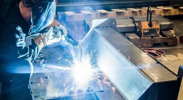
Welded Frames
Welds create continuous joints that behave like solid metal. This improves stiffness and eliminates micro-movement. Weld size, heat input, and sequence directly affect geometry. Significant welds add strength but increase distortion. Small welds reduce heat but may not be able to support heavy loads.
Heat control is critical. Welding produces residual stresses that pull the structure out of alignment. Common issues include diagonal twist, bowed faces, and pulled corners. Controlled patterns such as back-step welding or staggered welds help balance heat and reduce distortion.
Bolted and Riveted Joints
Bolted joints are beneficial when the frame needs to be adjustable, modular, or serviceable. Proper preload keeps joints tight and prevents them from slipping. Under-tightened bolts introduce micro-movement, which reduces stiffness and creates noise. Over-tightened bolts deform thin sheet metal and damage the edges of holes.
Thin-gauge sheet metal requires reinforcement. Backing plates, collars, and formed flanges spread the load and protect the joint. These features maintain the area’s flatness even when torque reaches the recommended values, typically ranging from 6 to 35 Nm, depending on the bolt size and material.
Manufacturing Process Choices
Fabrication steps significantly impact how closely the frame aligns with its intended design. The sections below illustrate how cutting, bending, and welding affect the final accuracy.
Cutting, Bending, and Forming Considerations
Accurate cutting ensures a clean fit-up. Burrs and tapered edges create stress points and alignment errors. Smooth cuts improve joint contact and reduce weld voids.
Bending introduces its own challenges. Minimum bend radius rules prevent cracking; for steel, a radius at least equal to the material thickness is standard. Springback varies with alloy and thickness. A 3 mm mild-steel bend typically springs back 1–2°, while high-strength steel may spring back more.
Formed shapes offer free stiffness. A simple flange, return, or hem can significantly increase rigidity without adding weight. Designers often reduce cost by replacing thick plates with thinner, well-formed panels.
Welding Sequence and Distortion Control
Welding is one of the most significant contributors to final frame accuracy. Heat pulls the metal toward the weld, creating distortion. The longer and hotter the weld, the greater the distortion. This is why balanced weld sequences matter.
Tack welding the entire frame locks the geometry before full welding starts. Small weld sections applied across opposite areas balance heat flow. Techniques like stitch welding or intermittent welds reduce total heat input. Strong fixtures resist movement and keep alignment within tolerance.
Typical large-frame distortion after uncontrolled welding can reach 2–4 mm. Controlled sequences and fixturing reduce this to under 1 mm, which protects rail mounting surfaces and panel interfaces.
Surface Treatment and Corrosion Protection
Surface finishing protects the frame from corrosion and wear. Powder coating typically reaches a thickness of 60–90 μm and offers strong impact resistance. Plating, anodizing, and chemical films provide thinner but more conductive protection for sensitive assemblies.
Environmental conditions guide the finish choice. High-humidity or chemical environments require stronger corrosion layers. High-vibration machines benefit from coatings that resist chipping. Strong protection helps preserve stiffness by preventing long-term weakening at joints and edges.
Quality Control and Verification
Checking alignment and stiffness ensures the frame performs as expected. The points that follow show how inspection and testing confirm structural stability.
Dimensional Accuracy and Alignment Checks
Datums define all future measurements. Choosing stable areas—often near tube intersections or thick panels—keeps inspection reliable. Common flatness expectations for medium-sized frames range from ±0.2 to ±0.5 mm, depending on the design.
Diagonal measurements quickly reveal twist. A difference of more than 1 mm on large frames often indicates welding distortion or assembly pressure. Laser alignment tools or simple fixture-based checks both work well for confirming straightness and parallelism across long spans.
Large frames may require section-by-section inspection. Checking each weld region or formed panel keeps minor distortions from accumulating into significant errors.
Stress, Deflection, and Fatigue Considerations
Static loads shape initial deflection, while dynamic loads define long-term stability. Thin sections, long spans, and sharp corners amplify bending. Studies on sheet metal structures often show that reinforcing only high-stress areas can reduce total deflection by 20–40%.
Fatigue becomes critical in machines running at 20–80 Hz, which is common in automation equipment. Weld toes and joint transitions are common origins of cracks: smooth load transitions, rounded internal corners, and reinforced joints slow fatigue growth. Bolted joints must maintain preload; if preload drops, micro-slip accelerates wear and reduces stiffness.
Vibration also affects accuracy. Light, flexible panels amplify vibration. Extra ribs or strategically placed mass dampers can stabilize the structure without overloading the frame.
Prototype Testing and Iteration
Prototype runs expose issues that CAD and FEA cannot show. Bending, vibration, and thermal tests reveal weak zones, misaligned holes, or excessive springback. These findings guide changes before full production.
Small batches reduce risk. They demonstrate how repeatable the process is and whether fixtures effectively control welding distortion. Adjustments in weld length, fixturing points, or bend tooling often eliminate the most common accuracy defects.
Environmental and Long-Term Performance
Real-world conditions change how a frame behaves over time. The following points cover temperature, vibration, and corrosion factors that affect long-term rigidity.
Thermal Expansion and Temperature Stability
Different metals expand at different rates. Steel expands less than aluminum, so mixing them can cause alignment drift as temperatures change. This mismatch is noticeable near heat sources such as motors and drive systems.
Thermal shields, ventilation paths, and spacing reduce temperature swings. Machines operating at elevated internal temperatures often benefit from reinforcing long rails or adding expansion slots to panel mounts. Stable temperature creates stable geometry.
Vibration, Shock, and Dynamic Loads
Fast-moving machines produce constant vibration. Over time, this affects joints, panels, and mounting surfaces. Short load paths, stiff corners, and wide bases reduce vibration transfer. These features also protect sensitive components like sensors or linear guides.
Damping materials absorb energy: rubber isolators, composite pads, and even sand-filled cavities lower vibration amplitude. Shock loads require reinforced corners and thicker bracket zones to absorb impact without deformation.
Corrosion, Wear, and Maintenance Planning
Environmental exposure slowly reduces stiffness. Corrosion begins at welds, edges, and hardware interfaces. Powder coating at 60–90 μm provides strong resistance, while plating protects areas where conductivity or thin films are required.
Maintenance access is equally important. Frames with reachable fasteners and removable covers avoid forced disassembly, which can stress the structure. Regular inspection prevents minor corrosion or bolt loosening from turning into structural problems.
Design for Assembly (DFA) and Serviceability
Good assembly planning helps the frame stay accurate during installation and maintenance. The sections below highlight features that make the frame easier to build and support.
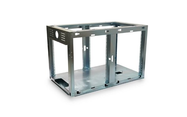
Modular Frame Architecture
Breaking large frames into modules improves transport, assembly, and later upgrades. Modules align accurately when they use locating pins, tabs, or slots. These features reduce the chance of twist during tightening.
Modularity has trade-offs. More joints mean more potential alignment drift if not designed well. Reinforced joint areas and tight tolerances help control this risk. When done correctly, modular design speeds up installation while maintaining rigidity consistency.
Ease of Component Integration
Internal components should mount cleanly without forcing parts into position. Straight cable routes, broad mounting flanges, and proper clearance help the machine stay stable during operation. When components fit naturally, they add minimal stress to the structure.
A typical design trap is routing cables or hoses across load paths. These areas experience vibration and movement. Rerouting them into protected channels or separate brackets prevents wear and avoids transferring vibration into sensitive areas.
Access, Inspection, and Repair-Friendly Features
Frames that support maintenance last longer. Hinged panels, quick-release covers, and easily accessible fasteners enable technicians to inspect and tighten joints without disassembling major components. Easy access protects the frame from repeated high-force adjustments.
Placing inspection points near weld zones or high-stress corners makes it easier to spot fatigue early. This is especially useful in machines with continuous vibration. Simple access often prevents minor issues from growing into structural deformation.
Conclusion
Rigid machine frames come from consistent decisions across design, fabrication, and inspection. Geometry defines stiffness. Materials set strength and weight. Joints control how loads move between parts. Manufacturing steps determine how closely the final structure matches the design.
Quality checks verify alignment and prevent early drift. Environmental planning protects the frame from heat, vibration, and corrosion. Assembly-focused design keeps the structure easy to build, maintain, and upgrade.
Ready to Build a Stronger Machine Frame? Send your CAD files and get a quick quote with clear engineering feedback. We help you avoid alignment issues, reduce rework, and build rigid, production-ready frames.
Hey, I'm Kevin Lee

For the past 10 years, I’ve been immersed in various forms of sheet metal fabrication, sharing cool insights here from my experiences across diverse workshops.
Get in touch
Kevin Lee
I have over ten years of professional experience in sheet metal fabrication, specializing in laser cutting, bending, welding, and surface treatment techniques. As the Technical Director at Shengen, I am committed to solving complex manufacturing challenges and driving innovation and quality in each project.
Related Resource

Fingerprint Resistant Stainless Steel: How It Works,and How to Choose


