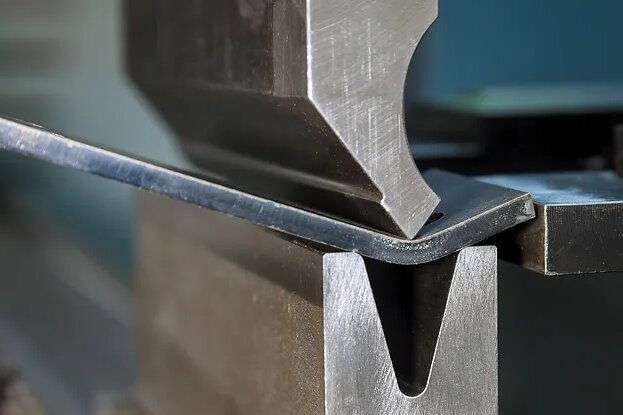
Le pliage de la tôle semble simple, mais le métal subit un mélange complexe de tension et de compression. Si ces forces se déplacent, même légèrement, la pièce ne conserve plus la forme prévue.
Les déformations se produisent pour des raisons prévisibles. Comprendre comment les contraintes se déplacent dans la tôle permet aux concepteurs et aux opérateurs de mieux contrôler le processus. Cette connaissance leur permet d'éviter les déformations, les courbures, les torsions et les erreurs dimensionnelles avant que les pièces n'atteignent l'atelier de production.
Modèles de déformation courants
Différents types de distorsions proviennent de différents déséquilibres de stress. En reconnaissant le schéma, il est plus facile de remonter à la cause première.
Déformation et torsion
La torsion se développe lorsqu'un côté du pli s'étire plus que l'autre. Même une différence d'étirement de 0,1 mm se traduit par une torsion de plusieurs degrés sur un panneau de 300 à 600 mm. Les feuilles minces de moins de 1,5 mm réagissent le plus fortement car elles manquent de rigidité.
Les opérateurs le constatent souvent lorsque la pièce bascule sur une table plate ou lorsqu'une bride allongée refuse de se redresser pendant l'assemblage.
Nettoyage des hydrocarbures et ondes de surface
Les panneaux larges perdent leur tension interne lors du pliage et forment des ondulations douces. Ce phénomène apparaît le plus souvent dans les matériaux de 1,0 à 1,5 mm, car ils fléchissent facilement.
Il suffit d'une légère pression du doigt pour que le panneau s'ouvre et se ferme. Cette instabilité est due à une tension inégale exercée sur le panneau après sa formation.
Effondrement de la bride sur des courbes courtes
Une bride doit être suffisamment longue pour résister à la force du poinçon. Lorsque la bride est plus courte que l'ouverture de l'emporte-pièce en V, elle ne peut pas rester droite.
Par exemple, le pliage d'un acier de 1,2 mm avec une matrice de 8 mm nécessite une bride d'au moins 8 à 10 mm. Tout ce qui est plus court se plie vers l'extérieur ou se bombe, quelle que soit l'habileté de l'opérateur.
Distorsion des trous et des caractéristiques près des lignes de pliage
Le pliage étire la zone de pliage de 8-15%. Si un trou se trouve à l'intérieur de cette zone, le métal qui l'entoure s'étire de façon irrégulière.
Les trous ronds deviennent ovales. Les fentes se déplacent latéralement. Les languettes se déplacent de 0,2 à 0,6 mm en fonction du matériau et de l'épaisseur. Les métaux tendres comme l'aluminium se déforment encore plus rapidement.
Causes de déformation lors du pliage de la tôle
La plupart des défauts de pliage de la tôle ne sont pas dus à une seule erreur. Ils résultent d'interactions entre la conception, le matériau et le processus de pliage.
Facteurs de conception qui amplifient le stress
De petites décisions peuvent augmenter considérablement la pression locale :
- Les trous ou les fentes trop proches des plis affaiblissent la zone de pliage.
- Les brides plus courtes que l'ouverture de la filière ne peuvent pas stabiliser le pli.
- Les rayons serrés surchargent la surface extérieure et provoquent des étirements ou des fissures.
- Les géométries déséquilibrées s'inclinent vers le côté le plus faible.
Une simple modification, comme le déplacement d'un élément de 1 à 2 mm plus loin, peut éliminer la déformation.
Comportement des matériaux à l'origine de la déformation
Les métaux ne se plient pas tous de la même manière :
- Les matériaux minces exagèrent les petites incohérences.
- L'aluminium s'étire facilement et présente plus d'ondulations.
- L'acier inoxydable a besoin d'une force plus importante et se ressoude plus difficilement.
- La direction du grain modifie la façon dont le métal tolère la tension.
Une erreur d'orientation du grain peut à elle seule augmenter le risque de fissure de 20-40%.
Conditions du processus qui influencent la précision
La configuration du pliage influe fortement sur la façon dont le matériau se déplace :
- Une mauvaise séquence de pliage emprisonne les tensions dans les coins.
- Les outils usés déplacent la ligne de pliage de 0,05 à 0,10 mm.
- Les brides non soutenues s'affaissent sous leur propre poids.
- La chaleur dégagée par le soudage ou le marquage provoque une déformation retardée.
- Un tonnage inégal sur le frein crée des angles effilés.
Même avec une conception et un matériau parfaits, un processus instable peut tordre un panneau au-delà de la tolérance.
Stratégies de conception pour prévenir les déformations
Une bonne conception réduit les contraintes avant le pliage. Lorsque la géométrie, l'espacement et les rayons correspondent au comportement du métal dans des conditions de formage réelles, la pièce reste stable et cohérente.
Utiliser des rayons de courbure adaptés aux limites du matériau
Le métal se plie proprement lorsque le rayon maintient la déformation en deçà de la plage élastique-plastique sûre du matériau. Un rayon trop serré comprime trop fortement l'intérieur et étire l'extérieur au-delà de ce que la tôle peut absorber.
Lignes directrices pratiques en matière de rayon utilisées dans la production :
| Matériel | Rayon intérieur minimum | Notes |
|---|---|---|
| Acier doux | 1,0 × épaisseur | Formation stable, faible retour élastique |
| Acier inoxydable | 1,5 × épaisseur | Une force plus élevée, un rebond plus fort |
| Aluminium 5052 | 1,5-2,0 × épaisseur | Souple, sujet à des bosses superficielles |
| Aluminium 6061-T6 | 2,0 × épaisseur ou plus | Fragile à l'état T6, risque de fissuration |
Lorsque le rayon est trop petit :
- L'acier de 0,8 à 1,0 mm forme des plis à l'intérieur et écarte le grain à l'extérieur.
- L'aluminium augmente la déformation, ce qui provoque une ondulation de la surface.
- L'acier inoxydable développe des microfissures qui n'apparaissent qu'après le pliage.
- Dos d'âne augmente de 0,5 à 1,5° en fonction de la dureté
Un rayon légèrement plus grand stabilise le pliage, réduit la pression et rend les angles plus faciles à contrôler dans la production de masse.
Placer les trous, les fentes et les découpes suffisamment loin de la ligne de pliage
Les caractéristiques affaiblissent la zone de pliage. Lorsque le poinçon force le métal à tourner, toute découpe voisine devient le "point d'étirement", ce qui provoque des trous ovales ou des positions décalées.
Règles d'espacement testées par l'industrie :
- Espacement minimal : 2 × l'épaisseur
- Recommandé pour les tôles fines (≤1,0 mm) : 3 × épaisseur
- Pour les grands trous : diamètre du trou + épaisseur
- Pour les fentes ou les encoches : espacement ≥ largeur de la fente × 2
Distorsions courantes dans la production réelle :
- Décalage des trous 0,2-0,6 mm
- Les fentes s'allongent de 5-12%
- Les languettes dérivent de 0,15 à 0,30 mm
S'il n'est pas possible d'augmenter l'espacement, des découpes d'allègement de la courbure ou des séquences de courbure modifiées permettent d'absorber les contraintes.
La longueur de la bride doit être suffisante pour supporter la courbure.
Les brides courtes s'affaissent, s'enroulent ou ondulent parce qu'elles ne peuvent pas supporter la pression du poinçon.
Les longueurs minimales des brides sont basées sur la taille de la matrice en V :
| Épaisseur de la feuille | Ouverture typique d'un moule en V | Longueur minimale de la bride |
|---|---|---|
| 1,0 mm | 8 mm | 8-10 mm |
| 1,2-1,5 mm | 10-12 mm | 10-14 mm |
| 2,0 mm | 16 mm | 16-18 mm |
Les brides plus courtes que la largeur de la filière se déforment presque toujours. L'augmentation de la bride de 1 à 2 mm ou l'utilisation d'une filière plus petite améliore considérablement la stabilité.
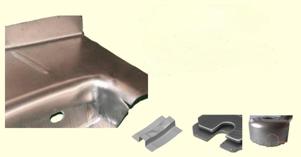
Ajouter des reliefs de courbure pour réduire les déchirures et les déformations d'angle
Les reliefs permettent à la feuille de se dilater et de se contracter. Ils protègent les zones d'angle où le matériau lutte contre deux forces opposées.
Dimensions recommandées du relief :
- Largeur : ≥ épaisseur de la tôle
- Profondeur: ≥ rayon + épaisseur
- Forme : rectangulaire ou arrondie pour l'inox/aluminium
Avantages constatés dans la production :
- Des angles plus nets
- Moins de déchirures dans l'acier à haute résistance
- Empêche la formation de plis en forme de V dans les virages serrés à 90°.
- Réduit les défauts cosmétiques sur l'aluminium brossé
Équilibrer la géométrie pour éviter les étirements unilatéraux
Le métal se plie vers le côté le plus faible. Les grandes découpes, les longues fentes ou les brides asymétriques créent une rigidité inégale et provoquent des torsions.
Les concepteurs peuvent améliorer la rigidité en
- Découpes en miroir des deux côtés lorsque c'est possible
- Ajout de nervures, d'ourlets, de coudes de retour ou de petites brides
- Augmentation de l'épaisseur des parois dans les régions soumises à des contraintes élevées
- Ajout de goussets d'angle aux grandes pièces en U
Un déséquilibre de rigidité aussi faible que 5% peut tordre un canal de 350-400 mm suffisamment pour provoquer des écarts d'assemblage.
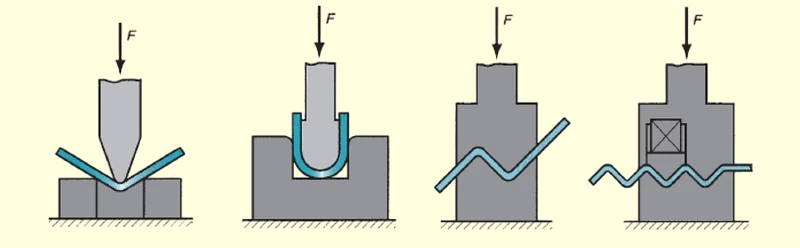
Prévoir une séquence de pliage qui laisse le métal se déplacer naturellement
Une séquence contrôlée permet à la feuille de tourner librement sans emprisonner de contraintes internes.
Principes généraux de séquençage utilisés dans les ateliers de production :
- Plier d'abord les grands angles
- Les petites brides sont-elles durables ?
- Éviter de former trop tôt des formes encadrées
- Laisser la feuille aussi longtemps que possible à plat.
- Soutenir la pièce lors des courbes ultérieures afin d'éviter les dérives de rotation.
Une séquence de pliage stable permet souvent de réduire la torsion de 30-50%, même sans modifier la conception.
Sélection et préparation des matériaux
Le matériau détermine le comportement du métal sous contrainte. Le choix de la bonne nuance, de la bonne épaisseur et de la bonne direction du grain rend le pliage plus prévisible et réduit la nécessité d'une compensation lourde.
Choisir le matériau en fonction de la performance de pliage requise
Des matériaux différents comportent des risques différents :
- Acier doux : formage facile, faible retour élastique, convient aux formes complexes à courbures multiples
- Aluminium 5052 : bonne aptitude à la flexion, mais s'étire facilement
- Aluminium 6061-T6 : solide, rigide, mais se fissure dans les virages serrés
- Inox 304 : un retour de printemps important et une demande de tonnage plus élevée
- Acier à haute résistance : sensible au rayon et sujet à la dérive angulaire
Lorsqu'une pièce doit être pliée plusieurs fois à proximité l'une de l'autre, l'acier doux ou l'aluminium 5052 donnent généralement les résultats les plus stables.
Choisir une épaisseur correspondant aux exigences de rigidité
Les feuilles minces se déforment rapidement. Elles sont légères et rentables, mais nécessitent un contrôle plus strict de la conception.
Seuils typiques où la déformation augmente fortement :
- Acier inférieur à 1,2 mm
- Aluminium inférieur à 1,5 mm
- Inox inférieur à 1,0 mm
L'augmentation de l'épaisseur, ne serait-ce que de 0,2 à 0,3 mm, peut réduire la torsion jusqu'à 40% en production réelle.
Choisir une direction de grain qui réduit le risque de fissuration et contrôle le retour élastique
La direction du grain influence l'étirement lors de la flexion.
Effets observés en production :
- Le pliage en travers du grain augmente le risque de fissure de 20-40%
- Le pliage dans le sens du grain réduit la fissuration mais augmente le retour élastique de 1 à 2°.
- L'aluminium présente une plus grande sensibilité au grain que l'acier
- L'acier inoxydable présente des modifications substantielles du retour élastique en fonction du grain.
Les concepteurs font souvent pivoter les modèles plats pour aligner les courbes critiques avec une orientation plus sûre du grain.
Utiliser un matériau dont l'épaisseur et la dureté sont constantes
Les variations de la qualité de la tôle modifient l'élasticité ou la résistance à la flexion du métal.
Plages de tolérance typiques des matériaux :
- Épaisseur : ±0,03-0,05 mm
- Dureté (HB) : ±10-15
- La variation de la composition chimique peut affecter le retour élastique de 0,5 à 1,0°.
Le fait de demander une classe de tolérance étroite ou d'utiliser un matériau provenant de la même bobine réduit la dérive de l'angle d'un lot à l'autre.
Envisager la détente ou le pré-pliage pour les alliages sensibles
Certains matériaux contiennent des contraintes résiduelles provenant de rouler, couper, ou perforation. Ces contraintes se libèrent de manière imprévisible lors de la flexion.
Pratiques utiles :
- Recuit léger pour l'aluminium 5052/6061
- Traitement thermique de détente pour les aciers à haute résistance
- Petits coudes d'essai pour mesurer le retour élastique avant la production en série
- Mise à niveau en ligne droite pour les grands panneaux afin de réduire la tension interne
Ces étapes permettent de stabiliser les pièces minces ou traitées thermiquement avant leur mise en forme.
Méthodes d'outillage et de soutien
L'outillage définit la manière dont la presse plieuse transmet la force à la tôle. Lorsque l'outillage est correctement adapté au matériau et à la géométrie du pliage, la déformation diminue fortement et la répétabilité s'améliore.
Choisir des poinçons et des matrices adaptés aux exigences en matière de matériau et de rayon
Le rayon du poinçon et la largeur de la matrice en V déterminent le chemin de déformation du métal. Un décalage augmente à la fois la contrainte du matériau et la variation du retour élastique.
Pratiques de l'industrie :
- Ouverture en V6-12 × épaisseur du matériau1.0 mm acier → 8-10 mm matrice en V
- 2,0 mm acier → 16-20 mm V-die
- Rayon de la pointe du poinçon: Acier doux : R = 0,6-1,0 mm
- Inoxydable : R = 1,0-1,5 mm
- Aluminium : R = 1,2-2,0 mm
Impact sur les performances :
- L'ouverture correcte de la matrice améliore la répétabilité de l'angle à ±0,5° dans le cintrage pneumatique
- Le basculement s'améliore généralement à ±0,3°.
- Le monnayage permet d'obtenir ±0,2° mais augmente le tonnage de 3 à 5 fois et accélère l'usure de l'outil.
Les matrices surdimensionnées provoquent des angles arrondis et incohérents. Les matrices sous-dimensionnées créent des plis, des rides ou des fissures sur la pièce, en particulier dans les rayons de courbure inférieurs à 1× l'épaisseur.
Maintenir la surface de l'outil propre et intacte
Les marques d'outils font partie des défauts. Un simple éclat sur l'arête de la matrice peut déplacer la ligne de pliage de 0,05 à 0,10 mm. L'aluminium fin amplifie ce phénomène, présentant des bosses même en cas de poussière ou de revêtement écaillé.
Les meilleures pratiques sont les suivantes :
- Nettoyage des matrices entre les lots
- Élimination des bavures incrustées à l'aide d'une pierre fine
- Éviter le frottement métal sur métal lors de l'installation
- Vérification de la rectitude du poinçon à l'aide de jauges d'épaisseur
Les ateliers qui plient des matériaux de 0,8 à 1,2 mm inspectent généralement l'état de l'outil tous les 300 à 500 plis. Les travaux à haut volume sur l'acier inoxydable nécessitent des contrôles encore plus rapprochés en raison de la pression et de la friction plus élevées.
Soutenir les pièces longues ou flexibles pour éviter l'affaissement et la dérive angulaire
La gravité affecte la précision. Une bride allongée ne s'affaisse que de quelques millimètres, mais sur des gabarits fins, cela suffit à décaler l'angle de 1 à 2°.
Recommandations de soutien :
- Les pièces d'une longueur supérieure à 300-350 mm doivent être soutenues par des bras.
- L'aluminium mince (≤1,5 mm) nécessite des ailes de calibre arrière ou un support à deux points.
- Les panneaux d'une largeur de ≥600 mm nécessitent souvent des tables frontales réglables
Lorsqu'elle n'est pas soutenue, la pièce tourne, forçant un côté à se plier plus profondément. La conicité qui en résulte peut atteindre une différence de 1° par 300 mm de longueur.
Utiliser des montages personnalisés pour les géométries instables ou à faible rigidité
Les pièces légères, les panneaux perforés et les brides étroites ne s'adaptent pas parfaitement aux jauges arrière standard.
Les supports personnalisés permettent de résoudre ce problème :
- Contact sur toute la surface
- Empêcher la rotation lors de l'engagement du poinçon
- Guidage des pièces asymétriques dans une position cohérente
Les fixations sont standard dans les panneaux HVAC, les boîtiers électroniques et les composants minces en acier inoxydable où la rigidité est faible et les tolérances serrées.
Conclusion
La tôle se plie mieux lorsque la conception, le matériau, l'outillage et le processus fonctionnent ensemble. Chaque choix influe sur la façon dont le métal s'étire et se comprime pendant le pliage. Lorsque ces choix restent dans des limites stables, la pièce conserve sa forme. Les angles restent proches de la cible. Les surfaces restent plates. Les trous conservent leur position.
La plupart des déformations sont dues à quelques causes bien connues. Les rayons étroits augmentent la déformation. Les brides courtes perdent leur support. Les trous situés près des lignes de pliage se déforment. Les tôles minces réagissent fortement à des changements mineurs. Les matériaux durs se déforment davantage. L'usure de l'outil, une force inégale et une mauvaise séquence de pliage ajoutent encore plus de variations.
Si vous travaillez sur une nouvelle pièce ou si vous essayez d'améliorer une conception existante, nous pouvons vous aider à la plier proprement. Vous pouvez envoyer vos dessins, l'épaisseur et le choix des matériaux.. Nous pouvons revoir la conception, suggérer des modifications simples, recommander de meilleurs rayons ou signaler les risques susceptibles de provoquer des torsions ou des déformations.
Hey, je suis Kevin Lee

Au cours des dix dernières années, j'ai été immergé dans diverses formes de fabrication de tôles, partageant ici des idées intéressantes tirées de mes expériences dans divers ateliers.
Prendre contact
Kevin Lee
J'ai plus de dix ans d'expérience professionnelle dans la fabrication de tôles, avec une spécialisation dans la découpe au laser, le pliage, le soudage et les techniques de traitement de surface. En tant que directeur technique chez Shengen, je m'engage à résoudre des problèmes de fabrication complexes et à favoriser l'innovation et la qualité dans chaque projet.
Ressources connexes

Acier électro-galvanisé : guide de fabrication et de sélection

Poinçonnage ou découpe laser : Coût, vitesse et compromis DFM

Usinage d'angle : Ce qui détermine le coût et la qualité des pièces
