The main difference between a mold and a die is the material’s physical state during forming. A mold shapes liquid or molten materials (like plastic) inside a closed cavity until they solidify. A die cuts or deforms solid materials (like sheet metal) using extreme mechanical pressure.
Understanding this fundamental distinction is just the first step. For engineers and procurement managers, confusing the capabilities of molds and dies can lead to catastrophic tooling costs, compromised part tolerances, and weeks of lost lead time.
This guide breaks down the core engineering differences between these tools, how to select the right manufacturing route for your part’s geometry, and how to accurately evaluate the total cost of ownership (TCO) before committing to a $20,000 tooling investment.
Quick Answer: The Engineering Distinction
- Mold: Shapes liquid or semi-liquid materials (like molten plastic or metal) by prioritizing uniform flow and controlled cooling inside a closed cavity.
- موت: Cuts, forms, or forces solid materials (like sheet metal) into shape, demanding high shear strength and precise clearances to withstand millions of physical impact cycles.
- (Note on terminology: Die casting injects molten metal into a steel cavity. While it functions mechanically like a mold, industry convention universally refers to this tool as a “die.”)
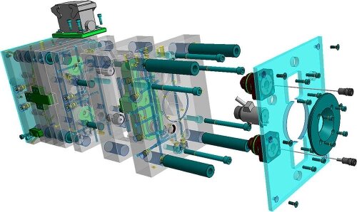
Understand Mold and Die Differences and Types
Manufacturing tools are categorized by how they interact with the raw material. Understanding this interaction clarifies why certain tools require specific maintenance schedules and engineering tolerances.
Forming Methods: Cavity Filling vs. Plastic Deformation
The primary distinction lies in the state of the material during forming.
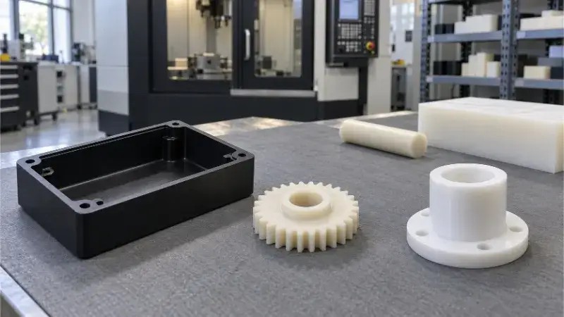
Molds rely on cavity forming. The material is heated until it reaches a fluid state, injected into the tool, and assumes the shape of the negative space inside. For example, a plastic electronics enclosure is formed by managing the thermal dynamics of cooling liquid resin.
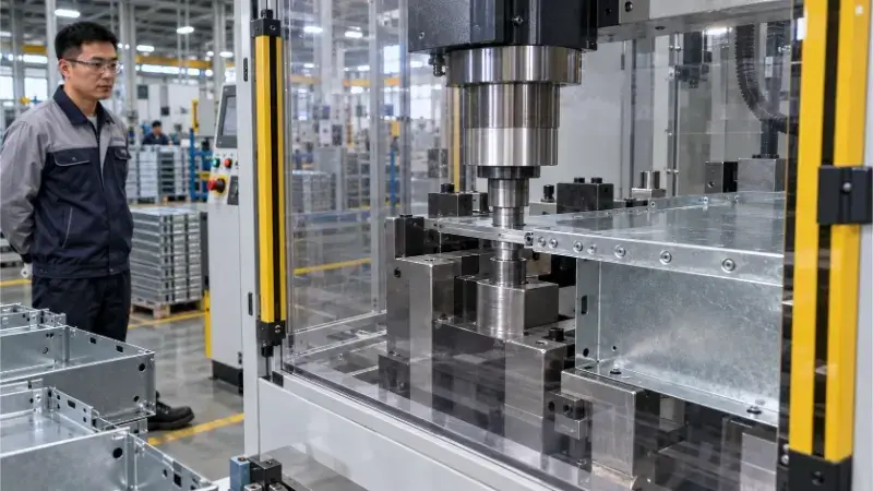
Dies generally rely on blanking or plastic deformation. They apply severe mechanical force to cut solid materials or bend them past their yield strength. A steel mounting bracket is formed by forcing a metal sheet into shape, meaning the die must absorb massive shock loads without fracturing.
Tool Components and Tolerance Demands
Because they handle materials in different physical states, molds and dies require completely different internal architectures and precision metrics.
- Mold Components: The primary shaping components are the core (the protruding half) and the cavity (the recessed half). Since molds handle hot fluids, they require cooling channels to manage material shrinkage. They use ejector pins to remove parts safely. To prevent flash (material leaking between halves), mold guide pins and bushings are often machined to strict tolerances, typically around ±0.005 mm.
- Die Components: The primary components are the لكمة (the male tool applying force) and the die matrix (the female tool receiving the cut). Dies require a stripper plate to pull the work-hardened metal off the punch. For a die to cut cleanly without creating excessive burrs, the clearance between the punch and the die matrix is highly critical—usually engineered to 5% to 10% of the material thickness, depending on the metal’s shear strength.
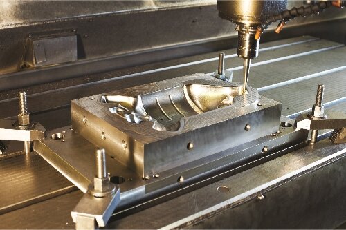
Common Tooling Configurations
Tooling is specified based on the required operation and volume. Rather than a rigid catalog, tooling is classified by how the cavity or press operation is configured.
| Tooling Category[cite: 27] | Common Configurations[cite: 27] | Typical Production Run[cite: 27] |
|---|---|---|
| قوالب الحقن[cite: 27] | Single-cavity, multi-cavity, family molds.[cite: 27] | 10,000 to 1,000,000+ parts.[cite: 27] |
| ختم يموت[cite: 27] | Blanking dies, bending dies, progressive dies.[cite: 27] | 5,000 to millions of stamped components.[cite: 27] |
| Casting Dies[cite: 27] | Cold-chamber, hot-chamber dies.[cite: 27] | 5,000 to 500,000+ metal structural parts.[cite: 27] |
Choose a Production Route Before Ordering Tooling
Committing to hard tooling involves significant capital and time. The choice of manufacturing process must be driven by part geometry, production volume, lead time constraints, and the maturity of the design.
Material and Geometry Constraints
Part geometry directly limits the available forming processes.
Sheet metal stamping requires a uniform material thickness throughout the part. If your design features varying wall thicknesses, internal webs, or complex solid features, stamping is physically impossible.
Injection molding (for plastics) and die casting (for metals) accommodate variable wall thicknesses and complex internal geometries. However, these processes require engineered draft angles (usually 1^\circ to 3^\circ) so the part can eject. If the part requires deep, narrow holes or undercuts, the tooling will need side-actions or lifters. These moving parts drive up the initial cost of the mold and introduce new wear points that require regular maintenance.
Production Requirements and Lead Times
Tooling selection depends heavily on the expected total volume, order frequency, and lead time tolerance.
Hard tooling (like H13 or D2 steel molds and dies) typically requires 4 to 8 weeks to machine, assemble, and trial (T1). If you need parts in two weeks, hard tooling is immediately disqualified.
Design stability is equally critical due to Engineering Change Orders (ECOs). Modifying a CNC program costs almost nothing. Modifying a hardened steel mold—especially if it requires welding material back into a cavity or remachining a die edge—can cost thousands of dollars and delay production by weeks. If the product is in its early lifecycle and dimensions may change based on user feedback, delay hard tooling.
Prototype Alternatives and Validation Limits
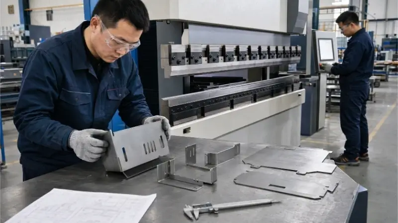
Before ordering production molds or dies, transitional methods like التصنيع باستخدام الحاسب الآلي أو القطع بالليزر with a press brake are used to verify fit and function.
However, engineers must understand what a prototype can and cannot verify.
- أ CNC-machined plastic part verifies assembly fitment, but it will not highlight injection molding defects like sink marks, weld lines, or warpage caused by uneven cooling.
- أ laser-cut and brake-formed metal part verifies hole placements, but it will not exhibit the work-hardening, die roll, or springback characteristics of a part punched at high speed in a stamping die.
Case Study: Scaling a Custom Steel Bracket
This table illustrates the transition from prototype to mass production for a standard metal bracket, highlighting why different processes are chosen at different stages.
| Production Stage[cite: 28] | Manufacturing Route[cite: 28] | الاستثمار في الأدوات[cite: 28] | Part Price[cite: 28] | مهلة[cite: 28] | ECO Flexibility[cite: 28] |
|---|---|---|---|---|---|
| Prototype (50 units)[cite: 28] | Laser Cutting + Manual Press Brake[cite: 28] | $0[cite: 28] | $8.50[cite: 28] | 3 Days[cite: 28] | عالي (Update CAD only)[cite: 28] |
| Pilot Run (2,000 units)[cite: 28] | Simple Blanking + Bending Die[cite: 28] | $3,500[cite: 28] | $2.20[cite: 28] | 3 Weeks[cite: 28] | قليل (Requires tooling modification)[cite: 28] |
| Mass Production (50,000 units)[cite: 28] | Progressive Stamping Die[cite: 28] | $18,000[cite: 28] | $0.45[cite: 28] | 6 Weeks[cite: 28] | منخفضة جداً (High cost to modify stages)[cite: 28] |
Each transition depends on confirmed demand volume and a locked design, preventing unnecessary capital risk and lead-time bottlenecks at the early stages of a project.
Design Parts to Reduce Forming and Dimensional Problems
Tooling complexity, defect rates, and future engineering change order (ECO) costs are largely determined before the first steel block is ever cut. Certain geometric features directly trigger failure modes in both molds and dies.
Flow and Shrinkage: Plastics vs. Metals
Materials behave fundamentally differently depending on whether they are cooling from a liquid polymer melt or solidifying from a molten metal state.
- ميزة: Variable wall thicknesses across a single part.
- Plastic Molding Issues: Thick sections cool much slower than thin sections. As the thicker plastic cools and shrinks, it pulls material inward, creating visual sink marks on the surface or causing the entire part to warp out of tolerance.
- Metal Casting Issues: In aluminum die casting, isolated thick sections cut off from the flow of pressurized molten metal will develop internal porosity or shrinkage cavities as the metal solidifies, compromising structural integrity.
- Feasible Solutions: Maintain uniform wall thickness. Coring out thick sections to create a ribbed structure maintains strength while preventing shrinkage defects.
- Expert T1 Strategy (The “Metal-Safe” Principle): Shrinkage rates are rarely 100% predictable. Experienced toolmakers adopt a “metal-safe” (or “steel-safe”) approach. For a critical inner diameter (ID) on a plastic part, the mold cavity is intentionally machined slightly undersized. During the first trial (T1), if the part ID shrinks too much, it is relatively easy to machine a few microns of steel off the mold. Adding steel back via welding is expensive and risks cracking.
Clearance and Springback
For stamping dies, achieving a precise geometric tolerance depends entirely on managing the mechanical limits of the sheet metal.
- ميزة: A 90° bent steel bracket where the distance from the bend to a datum hole must be held to ±0.2 mm.
- Issues: When the die punch bends the metal and retracts, the material’s natural elasticity causes it to unbend slightly—a phenomenon known as سبرينجباك. Furthermore, if the die clearance (the gap between punch and die matrix) is incorrect for the sheet’s thickness and yield strength, the metal will fracture unevenly, leaving excessive burrs.
- Feasible Solutions: Engineers compensate for springback by over-bending (e.g., tooling designed for a 92° bend to achieve a 90° resting state). Because springback varies by material batch, rolling direction, and thickness, the final punch geometry often requires manual tuning after the initial press runs.
Draft and Undercuts
Ejection is a critical phase. The part must leave the rigid steel tool without dragging, scratching, or sticking.
- ميزة: Vertical walls (perpendicular to the parting line) and snap-fit hooks (undercuts).
- Issues: Perfectly vertical walls create a vacuum lock and scrape against the steel during ejection, leading to drag marks. Undercuts physically lock the part inside the mold cavity.
- Feasible Solutions: Apply a draft angle (typically 1° to 3°) to all walls parallel to the ejection direction. Redesign undercuts into pass-through cores (shut-offs) wherever possible. If an undercut is unavoidable, the mold requires mechanical side-actions or lifters. These moving components significantly increase the initial tooling cost and introduce wear points that demand frequent maintenance.
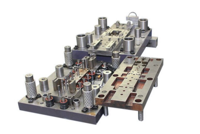
Select Tool Materials for the Operating Conditions
Specifying tool steel is not a one-size-fits-all decision. The choice must balance the thermal environment, the chemical nature of the raw material, and the expected mechanical stress.
The Cost Misconception: Procurement teams often assume expensive tooling is due to the high cost of premium steel. In reality, the raw steel block usually accounts for only 10% to 20% of the total mold cost. The true cost driver is machinability. Premium hardened steels (like D2 or H13) force CNC machines to run at slower feed rates, wear out cutting tools rapidly, and require extensive, slow Electrical Discharge Machining (EDM) hours.
Wear Resistance vs. Toughness
There is an inherent metallurgical trade-off between a tool’s ability to stay sharp (wear resistance/hardness) and its ability to absorb impact without fracturing (toughness).
- Cutting Edges: Blanking punches in a stamping die require extreme hardness (e.g., D2 steel hardened to 60-62 HRC) to maintain a sharp shearing edge over millions of strokes without dulling.
- Structural and Forming Components: Die blocks subjected to heavy impact, or deep-drawing dies facing severe compressive stress, require higher toughness (e.g., S7 shock-resistant steel). They must absorb shock to prevent catastrophic cracking, even if it means slightly lower wear resistance.
Heat and Corrosion Management
The operating environment often dictates the base material.
- Thermal Cycling: Die casting molds for aluminum operate under extreme thermal shock. The rapid cycle of injecting molten metal and blasting coolant causes thermal fatigue, leading to “heat checking” (micro-cracking on the cavity surface). H13 hot-work tool steel is the industry standard here due to its high-temperature stability.
- Corrosive Environments: Molding certain plastics, such as PVC or flame-retardant resins, releases corrosive off-gases that will quickly rust standard tool steels. Stainless steels (like 420 SS) or specialized nickel platings are required for the cavity blocks.
Treatments and Inserts
Instead of machining an entire massive tool from a difficult-to-cut superalloy, toolmakers rely on localized treatments and modular designs.
- Surface Treatments: Nitriding or PVD (Physical Vapor Deposition) coatings apply a microscopic layer of extreme hardness to the tool surface, improving wear resistance and reducing friction without making the steel’s core brittle.
- Interchangeable Inserts: High-wear areas—such as plastic injection gates or small piercing punches in a progressive die—are designed as removable inserts. When a punch dulls, the maintenance team replaces the small insert rather than pulling the entire tool off the press for remachining.
Typical Tooling Materials and Applications
| درجة المادة[cite: 29] | Ideal Operating Condition[cite: 29] | المزايا الرئيسية[cite: 29] | القيود الرئيسية[cite: 29] |
|---|---|---|---|
| Aluminum (QC-10)[cite: 29] | Low-pressure plastics, prototypes[cite: 29] | High thermal conductivity, excellent machinability[cite: 29] | Low wear resistance, easily dented[cite: 29] |
| P20 Steel[cite: 29] | General injection molding[cite: 29] | Pre-hardened (~30 HRC), good balance of cost/machining[cite: 29] | Insufficient for abrasive glass-filled resins[cite: 29] |
| H13 Steel[cite: 29] | High-temp casting, hot forging[cite: 29] | Outstanding thermal fatigue resistance[cite: 29] | Must be heat-treated after rough machining[cite: 29] |
| D2 Steel[cite: 29] | Cold stamping, blanking dies[cite: 29] | High hardness, holds a sharp cutting edge[cite: 29] | Low toughness, prone to chipping under shock[cite: 29] |
Control Accuracy During Mold and Die Manufacturing
Tooling precision dictates final part quality. However, machining hardened steel requires a specific sequence of operations and a strict management of cumulative tolerances.
Milling, Hard Milling, and EDM
No single machining method works for every feature. Toolmakers sequence processes based on material hardness, depth-to-width ratios, and internal corner radii.
- الطحن باستخدام الحاسب الآلي: Used for bulk material removal when the steel is in its annealed (soft) state. Modern High-Speed Machining (HSM) centers can also perform “hard milling” on heat-treated steel, leaving exceptional surface finishes and reducing reliance on EDM.
- Wire EDM (Electrical Discharge Machining): The go-to method for cutting the male punches and female die matrices in stamping tools. It cuts straight-through profiles with extreme precision (±0.002 mm) regardless of the steel’s hardness.
- Sinker EDM (Cavity EDM): Required for blind cavities that rotating cutters physically cannot machine.
- Case Example: A plastic mold requires a deep cooling fin cavity (
1 mm wide × 15 mmdeep) with sharp 90° internal corners. A CNC end mill cannot cut a sharp internal corner (it leaves a radius), and a cutter small enough to fit a 1ممgap would snap at that depth. Instead, the toolmaker mills a copper electrode to the exact shape of the fin, and uses Sinker EDM to slowly erode the deep cavity into the hardened steel block.
Surface Specifications
The surface finish of the tool directly dictates the part’s appearance, but it also governs the forming mechanics.
- Polishing vs. Texturing: A high mirror polish (SPI A-2) is mandatory for optical lenses and helps specific resins release during ejection. Conversely, EDM surfaces naturally leave a matte texture (VDI scale), which is often specified deliberately on consumer goods to hide fingerprints and mask minor injection sink marks.
- Die Friction: In metal deep-drawing dies, the draw radii must be highly polished. A rough surface will create excessive friction, causing the sheet metal to gall (cold weld to the die) and tear during the draw.
Datums, Fits, and the Reality of Tolerances
Achieving tight tolerances on individual components does not guarantee the assembled tool will function correctly.
- The Heat Treatment Variable: Steel warps and expands during the hardening process. A block machined perfectly to its datums in the soft state will lose its accuracy after the furnace. Therefore, critical fits cannot be finished before heat treatment.
- Re-establishing Datums: After hardening, the distorted steel block must go to a Precision Surface Grinder. The operator grinds the top, bottom, and side faces perfectly flat and square to re-establish the datum planes. Only then can Wire EDM or hard milling proceed accurately.
- Equipment vs. Part Tolerances: It is critical to distinguish between tooling manufacturing tolerances و final part tolerances. A high-end 5-axis CNC can hold a mold cavity dimension to ±0.005 mm. However, if the engineering team estimated a 1.5% plastic shrinkage rate, but the actual resin shrinks at 1.8%, the final molded part will fail inspection. High equipment precision cannot fix incorrect engineering assumptions.
Compare Tooling Investment and Total Production Costs
Evaluating a tooling quote requires looking past the initial sticker price. A cheaper mold or die often hides higher long-term maintenance costs or slower cycle times, which ultimately inflate the unit price. Procurement managers must analyze the Total Cost of Ownership (TCO).
Unpacking Upfront Costs
When comparing quotes from different toolmakers, ensure the scope of delivery is strictly identical. A comprehensive upfront tooling cost should break down:
- Design and Engineering (DFM): Time spent optimizing the part for manufacturability and designing the tool architecture.
- Raw Materials: The grade of the steel blocks (e.g., P20 vs. H13), custom hot runner manifolds, or specialized die sets.
- Machining and Assembly: The bulk of the cost, covering CNC, Wire/Sinker EDM, precision grinding, and manual fitting.
- Trials and Modifications: The cost of press time for T1 (first trial) and the expected rounds of tuning to reach dimensional compliance.
If a quote is surprisingly low, the toolmaker may be substituting a lower-grade steel, excluding a necessary hot runner system, or planning to charge extra for every subsequent trial run.
Calculating the Break-Even Volume
When deciding between two viable production routes (e.g., Laser Cutting + Press Brake vs. Progressive Stamping), the decision comes down to math.
The Simplified Formula:
Break-Even Volume = Difference in Fixed Tooling Costs ÷ Difference in Unit Prices
Example Scenario:
- Route A (Laser/Brake): Tooling = 0, Unit Price = 5.00
- Route B (Stamping Die): Tooling = 12,000, Unit Price = 1.00
- Break-Even Volume = 12,000 ÷ (5.00 − $1.00) = 3,000 units.
If your total expected lifetime volume is under 3,000 units, Route A is the more economical choice. Over 3,000 units, the $12,000 die pays for itself. (Note: This simplified calculation assumes that secondary operations, scrap rates, and inspection costs are already factored into the quoted unit price.)
Maintenance, ECOs, and Cycle Time Penalties
Tooling is not a one-time, “fire and forget” expense. Dies dull and molds foul.
- Cycle Time Penalties: A cheap mold often features poorly designed cooling channels. If a cheap mold requires 60 seconds to cool a plastic part, while an optimized (but slightly more expensive) mold does it in 40 seconds, that 20-second difference will drastically inflate your per-unit machine time costs over a 100,000-part run. Cheap tooling is often the most expensive to run.
- صيانة: Stamping dies require regular press downtime to pull the tool and regrind the cutting punches. Injection molds require flushing of cooling channels and replacement of worn ejector pins. Ensure the contract specifies who bears routine maintenance costs.
- Engineering Change Orders (ECOs): Modifying hardened steel after heat treatment is incredibly expensive. If the design is not locked, delay hard tooling.
Tooling Cost Comparison Matrix
| Cost Category[cite: 30] | Route A: CNC / Sheet Metal (No Tooling)[cite: 30] | Route B: Soft Tooling (e.g., P20 Mold)[cite: 30] | Route C: Hard Tooling (e.g., D2/H13)[cite: 30] |
|---|---|---|---|
| Upfront Investment[cite: 30] | Zero to minimal (fixtures only)[cite: 30] | منخفضة إلى متوسطة[cite: 30] | عالي[cite: 30] |
| Per-Unit Cost[cite: 30] | عالي[cite: 30] | متوسط[cite: 30] | منخفضة جداً[cite: 30] |
| Maintenance Burden[cite: 30] | لا يوجد[cite: 30] | Low (shorter overall life)[cite: 30] | High (requires skilled upkeep)[cite: 30] |
| Cost of Design Changes[cite: 30] | Low (Update CAD/CAM)[cite: 30] | عالي[cite: 30] | Very High (Often requires weld/remachine)[cite: 30] |
Ready to move your design from prototype to production without the capital risk?
Navigating tooling investments, material selection, and tolerance stack-ups can make or break a project’s budget. At TZR, we believe you shouldn’t commit to a $20,000 hard tool until your design is unequivocally proven.
Stop guessing which manufacturing route is best. Upload your CAD for a Free DFM Review and Route Assessment Today
مهلا، أنا كيفن لي

على مدى السنوات العشر الماضية، كنت منغمسًا في أشكال مختلفة من تصنيع الصفائح المعدنية، وشاركت رؤى رائعة هنا من تجاربي عبر ورش العمل المتنوعة.
ابقى على تواصل
كيفن لي
لدي أكثر من عشر سنوات من الخبرة المهنية في تصنيع الصفائح المعدنية، وتخصصت في القطع بالليزر، والثني، واللحام، وتقنيات معالجة الأسطح. كمدير فني في شنغن، أنا ملتزم بحل تحديات التصنيع المعقدة ودفع الابتكار والجودة في كل مشروع.
الموارد ذات الصلة