Sheet metal reinforcement methods increase the structural rigidity of thin panels without adding thickness. Techniques involve altering the part’s geometry through flanging, hemming, and stamping ribs, or integrating external supports like welded gussets and channels.
Increasing sheet thickness is the easiest way to reduce panel flex, but it is rarely the smartest. Relying on thicker gauges simultaneously adds dead weight, drives up material costs, and requires massive press brake tonnage.
A better sheet metal design places stiffness exactly where the load occurs. This guide compares 11 practical geometry and structural reinforcement methods, breaking down their best uses, manufacturing limits, and cost impact on production.
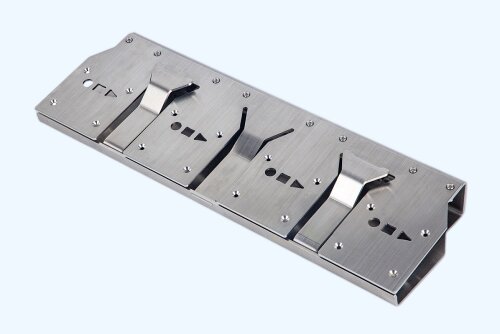
Match Reinforcement to the Failure Mode
Before selecting a method, you must identify the structural problem. When a sheet metal part flexes or fails, engineers generally rely on three routes:
- Change the geometry
- Add a separate support
- Increase the gauge or select another material
Increasing thickness or switching materials is a design alternative, not a structural reinforcement technique. This guide focuses strictly on changing geometry and adding supports.
Strength, Stiffness, and Buckling
Different failures require different reinforcements:
- Stiffness: How much the part bends under load (e.g., an enclosure door flexing when pressed).
- Strength: When permanent deformation or failure begins (e.g., a stripped thread in a mounting hole).
- Buckling: Sudden instability in a thin or slender section (e.g., a long bracket folding under compression).
- Fatigue: Damage caused by repeated loading cycles over time (e.g., a hinge mount tearing after thousands of uses).
Load Paths and Failure Areas
Look at how forces travel through the part. Reinforcement structures must support the load path and protect areas prone to distortion. Check these specific areas during design:
- Large flat panels
- Long unsupported edges
- Corners and bend transitions
- Hinges and handles
- Fastener holes
- Motors and heavy internal parts
- Welded joints
Quick Method Selection
| Part problem | Recommended methods | Relative cost |
|---|---|---|
| Flexible edge | Flange, hem or wired edge | Low |
| Weak threaded hole | Flanged or extruded hole | Low |
| Oil-canning panel | Ribs, beads or cross-braking | Low to medium |
| Vibrating large panel | Corrugations or stamped channels | Medium |
| Weak corner | Gusset | Low to medium |
| Concentrated mounting load | Reinforcement plate | Medium |
| Long unsupported span | Added structural profile | Medium to high |
Reinforce Edges and Fastener Holes
Unreinforced edges deflect easily under load, and thin gauges struggle to hold threaded fasteners. The following methods address edge rigidity, handling safety, and localized connection strength.
Folded Edge Features
1. Edge Flanges and Return Bends
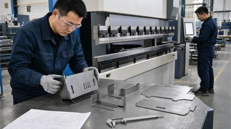
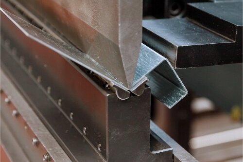
Adding a vertical flange or a return bend along an edge increases the cross-sectional depth, which directly reduces edge deflection. This method works well for covers, trays, brackets, and chassis edges.
- DFM Focus: Maintain the minimum flange height—typically 3 to 4 times the material thickness. If it is too short, the press brake bottom die cannot grip the sheet securely. Account for the bend radius, tooling access, and ensure holes are placed far enough from the bend line to prevent distortion.
- Cost Impact: Zero tooling cost, low unit cost. It generally only requires an additional press brake operation using standard V-dies.
2. Hems and Curls
Folding the metal edge back onto itself increases stiffness while eliminating sharp burrs. This is usually used for door panels, covers, and operator interfaces where human contact is frequent.
- DFM Focus: Select between an open, closed, or teardrop hem. Be cautious with closed hems (flattened completely)—forming them in materials thicker than 2mm or in harder alloys often causes surface fracturing along the bend.
- Production Pitfall: Beware of open hems in outdoor environments. They create crevices that trap pretreatment fluids. If not baked out properly, these fluids boil out during powder coating, ruining the finish and causing premature rust.
- Cost Impact: Medium unit cost. Requires two press brake strokes (an acute bend followed by flattening).
Rolled Edge Features
3. Wired Edges
This process involves rolling the sheet metal edge around a solid wire or metal rod to form a highly rigid cylindrical cross-section. It works well for ductwork, heavy-duty trays, and round tanks. It serves as a specialized method and is not a standard choice for precision electronics enclosures.
- DFM Focus: Calculate the correct rolling allowance based on the wire diameter. Assess tooling availability at your fabricator, as not all shops carry the specific curling dies.
- Cost Impact: Low tooling cost, but medium-to-high unit cost due to the manual handling and wire insertion required during assembly.
Formed Holes
4. Flanged and Extruded Holes
Flanged holes improve local rigidity around a cutout. Extruded holes draw the metal upward to create a collar, which increases the effective engagement length for tapped threads in thin materials. They are suitable for tapped holes, alignment pins, and mounting zones.
Engineer’s Note: A plain punched hole removes material, weakening the area. The structural reinforcement of an extruded hole comes from the work-hardened, formed collar surrounding it. For sheets under 1.5mm, this turns a weak 1-thread engagement into a secure 3-to-4 thread connection.
- DFM Focus: The primary constraints are formed height and material thinning. Pushing the extrusion too deep results in edge cracking. Check the hole-to-edge distance and ensure the forming direction (up or down) is explicitly marked on the drawing to avoid interference with internal mating components.
- Cost Impact: Moderate tooling cost, extremely low unit cost. If a custom punch is required, there is an upfront fee. However, once the tool is set up in the CNC punch press, the per-hole forming cost is nearly zero.
Control Flexing and Oil Canning in Large Panels
Large, flat sheet metal panels—like enclosure side walls and machine covers—are inherently weak against perpendicular forces. They easily bow under pressure and often suffer from “oil-canning” (a popping sound when the metal flexes back and forth). The solution is to disrupt the flat surface geometry.
Linear Stiffening Features
5. Ribs and Beads
Ribs and beads are linear protrusions stamped into the sheet to increase localized cross-sectional depth. This directly reduces panel deflection without adding weight. They work well for equipment housings, base plates, and large automotive panels.
- Engineering Note: Orientation dictates performance. A rib running parallel to the bending axis provides almost zero reinforcement. Ribs must be placed perpendicular to the expected load path to resist bending effectively.
- DFM Focus: Keep rib depth to a maximum of 2 to 3 times the material thickness to prevent the metal from tearing. Maintain generous radii at the ends of the ribs to avoid stress concentrations and tooling marks.
- Cost Impact: High tooling cost, low unit cost. Requires custom stamping dies, making it highly cost-effective for volume production but restrictive for low-volume prototypes.
Local Formed Features
6. Embosses and Dimples
Embosses are raised geometric pads used for mounting surfaces, while dimples form a conical or curved depression around a hole. Both methods use localized stretching to create a rigid zone. They are suitable for supporting hinges, casters, heavy fasteners, and motor mounts.
- Engineering Note: Do not confuse a structural dimple with a machined countersink. While both allow a screw to sit flush, a formed dimple leverages geometric depth and localized work hardening to significantly stiffen the mounting point against pull-out forces.
- DFM Focus: Design the corners of square embosses with a radius of at least 1 to 2 times the material thickness. Sharp corners will crack during the press stroke. Ensure enough flat clearance remains around the feature for fastener heads and installation tools.
Large-Panel Features
7. Cross-Braking
Cross-braking involves putting two diagonal bends (an “X” shape) across a large rectangular panel. This introduces a slight, controlled tension into the sheet, stiffening the surface and eliminating vibration and oil-canning. It is standard practice for HVAC ductwork, hidden equipment covers, and panels where perfect cosmetic flatness is not required.
- DFM Focus: Keep the bend very shallow—usually just enough to deflect the center of the panel by a few millimeters.
- Production Pitfall: Cross-braking slightly distorts the outer edges of the panel. If the panel needs to seal flat against a rigid frame with a gasket, keep mounting holes and perimeter edges well clear of the brake lines.
- Cost Impact: Zero tooling cost, low unit cost. It only requires two quick hits on a standard press brake.
8. Corrugations and Stamped Channels
Corrugations form a continuous wave-like profile, while stamped channels create deeper, wider integral grooves. They offer far more rigid directional reinforcement than cross-braking and work well for machine guards, floor panels, and heavy industrial enclosures.
- DFM Focus: Calculate the required press tonnage—stamping large channels requires massive force. Be mindful of internal interference: a 15mm deep channel stamped inward reduces your internal assembly clearance by exactly 15mm.
- Cost Impact: High tooling cost. Usually requires specialized stamping dies or a roll-forming line. Best reserved for repeatable, high-volume production.

Support Corners, Mounting Points, and Long Spans
When integral forming limits are reached, or when dealing with highly localized, extreme loads, you must add separate structural supports to the assembly.
Corner Support
9. Gussets
Gussets are triangular supports that reinforce 90-degree joints to prevent the angle from opening or closing under stress. They suit heavy-duty frames, chassis bases, and large cantilevered brackets.
- DFM Focus: Gussets can be formed (stamped directly into the bend) or added (a separate plate welded in place). Formed gussets work best for material under 3mm in volume runs. Separate welded gussets handle much heavier loads but require manual alignment.
- Production Pitfall: If using welded gussets outdoors, fully weld the seams. Stitch welding leaves tiny gaps that trap moisture and accelerate rust.
Point-Load Reinforcement
10. Local Reinforcement Plates
Also known as doubler plates, these are separate pieces of metal welded or riveted behind a high-stress area (like a heavy door hinge or motor mount). They distribute concentrated point loads over a much wider surface area of the thin main panel.
- DFM Focus: Avoid using excessively thick reinforcement plates or designing them with abrupt, square edges. A stiff, square plate welded to a thin panel simply shifts the stress concentration to the weld seam, causing fatigue cracking. Taper or radius the corners of the reinforcement plate for a smoother stress transition.
- Cost Impact: Zero tooling cost, medium unit cost. Ideal for low-volume production or prototypes where opening a custom die for an emboss isn’t financially viable.

Long-Span Support
11. Added Structural Profiles
For long unsupported spans—like massive equipment doors or heavy transport chassis—fabricators attach structural profiles (angle iron, U-channels, hat channels, or square tubes) directly to the back of the sheet metal.
- DFM Focus: Unlike stamped channels (Method 8), these are separate, thicker components. Pay close attention to the joining process. Excessive heat input from continuous welding will cause severe panel distortion and warping. To control this, fabricators use stitch welding (skip welding) rather than continuous seams, or switch to structural adhesives.
When adding structural profiles, the joining method dictates both the strength and the cosmetic finish. Use this quick comparison:
| Joining method | Main benefit | Main limitation |
|---|---|---|
| Spot welding | Fast for volume production | Heat input and visible marks |
| MIG or TIG welding | Strong and flexible | Distortion and finishing |
| Riveting | No welding heat | Holes and assembly access |
| Bolting | Removable | Possible loosening |
| Structural adhesive | Even load distribution | Preparation and curing |
For high-volume runs where cosmetic appearance matters less, spot welding is usually the most cost-effective. For low-volume enclosures requiring pristine outer surfaces, structural adhesives are becoming the industry standard.
Advanced Option: Sandwich Panels
If you need extreme rigidity with minimal weight, consider sandwich panels. Metal skins bonded to a honeycomb aluminum or polymer core provide a high stiffness-to-weight ratio. They suit aerospace, rail, and specialized transport. While they offer excellent structural performance, they require complex bonding, edge-closing processes, and specialized inspection, placing them outside standard sheet metal fabrication methods.
Check DFM, Cost, and Performance Before Production
Selecting a reinforcement method is only half the job. You must ensure the design is manufacturable, fits your budget, and integrates seamlessly into the final assembly.
Forming and Material Limits
You cannot apply the same forming rules to high-strength steel (HSS), 304 stainless steel, and 5052 aluminum. When adding formed features like ribs, hems, or flanges, carefully evaluate the material behavior:
- Springback: Harder materials will try to return to their original flat shape after bending. Compensate for springback by over-bending in the press brake tooling—do not simply loosen your dimensional tolerances on the drawing.
- Work Hardening: Stainless steel hardens rapidly during forming. Deep extrusions or sharp embosses may cause the material to crack.
- Grain Direction: Always orient heavy bends and ribs perpendicular to the material’s grain direction to prevent tearing, especially when working with hard-temper aluminum (like 5052-H32) or stainless steel.
- Press Capacity: Large stamped channels and corrugations require significant press tonnage. Check if your fabricator has the equipment size to handle the panel.
Joining, Finish, and Assembly
A structural reinforcement is useless if it causes an assembly failure down the line. Review the reinforced area against these common production issues:
- Internal Component Clearance: A welded stiffener or deep stamped rib might suddenly block a cable routing path, a cooling fan airstream, or the swing radius of an internal component.
- Fastener and Tool Access: If you add a heavy corner gusset, ensure an assembly worker can still fit a socket wrench or rivet gun into that corner.
- Drainage and Corrosion: Unwelded seams behind reinforcement plates, or open hems at the bottom of a panel, will trap water. For outdoor parts, design drainage weep holes and specify fully sealed welds to prevent crevice corrosion.
- Weld Distortion: Welding thick structural profiles to thin panels applies massive localized heat, which will warp the cosmetic face.
Cost and Design Validation
Your production volume should dictate your reinforcement strategy. Avoid designing features that require custom tooling if you are only building a prototype.
| Production stage | Practical options |
|---|---|
| Prototype (1-10 pcs) | Flanges, gussets, bolted profiles, and separate reinforcement plates. (Zero custom tooling). |
| Low volume (10-500 pcs) | Welded channels, cross-braking, and simple formed features using standard punch dies. |
| High volume (500+ pcs) | Stamped ribs, large embosses, and extruded holes. (Tooling cost is easily amortized). |
Before cutting metal, define how you will validate the reinforcement. Do not just ask for “stronger.” Specify measurable acceptance criteria on your drawing, such as:
- Maximum allowable deflection under a specific load (e.g., < 2mm deflection at 50kg).
- Fastener pull-out strength for extruded holes.
- Required fatigue cycles for moving parts like hinge mounts.
- Cosmetic limits: Acceptable weld marks, heat tint, or minor tooling indentations on the non-functional side.
For expensive, high-volume tooling, run a static FEA (Finite Element Analysis) simulation first. For standard enclosures, physical prototyping and static load testing remain the most practical validation methods.
Shop Example: A client designed a 1.2mm steel enclosure door that flexed heavily around the latch handle. Upgrading to a 2.0mm sheet fixed the flex but doubled the door weight, requiring more expensive hinges. Stamping reinforcing ribs offered the best weight-to-strength ratio, but the custom stamping die didn’t make financial sense for a 100-piece production run.
The final solution: We added a simple, press-braked hat channel to the back of the door using structural adhesive. It provided the exact rigidity needed, required zero custom tooling, and left no weld marks on the cosmetic outer face.
Conclusion
Good sheet metal design places stiffness exactly where it is needed without blindly increasing material thickness. Methods like flanging, hemming, cross-braking, and stamping ribs rely on smart geometry to drastically increase rigidity. For heavy, concentrated loads, adding separate supports like gussets, doubler plates, and structural profiles is the standard approach.
The best reinforcement method for your part will always be a calculated balance between the required load capacity, the specific material limits, acceptable weld distortion, and your expected production volume.
Stop paying for thicker sheets you don’t need. Whether you are designing a one-off prototype or scaling to high-volume production, Shengen’s engineering team can help you optimize for weight, strength, and tooling costs. Send your 2D or 3D CAD files to Shengen for a free DFM review and manufacturing quotation.
Hey, I'm Kevin Lee

For the past 10 years, I’ve been immersed in various forms of sheet metal fabrication, sharing cool insights here from my experiences across diverse workshops.
Get in touch
Kevin Lee
I have over ten years of professional experience in sheet metal fabrication, specializing in laser cutting, bending, welding, and surface treatment techniques. As the Technical Director at Shengen, I am committed to solving complex manufacturing challenges and driving innovation and quality in each project.