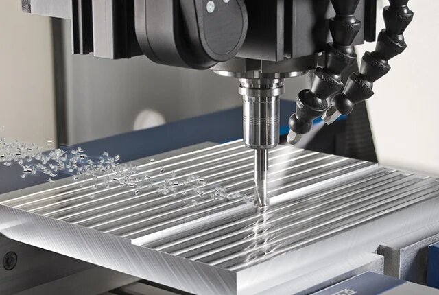
High-speed machining (HSM) is an advanced CNC milling process that combines extremely high feed rates with shallow cutting depths. Rather than relying on heavy, slow cuts, HSM uses light, consistent tool engagement to reduce cutting forces, minimize part distortion, and achieve precise surface finishes rapidly.
While the definition sounds straightforward, achieving true HSM on the shop floor is not as simple as maxing out your spindle RPM. It requires a flawless synchronization of dynamic machine motion, balanced tooling, and specific CAM strategies.
But running a spindle at 20,000 RPM doesn’t automatically lower your cost per part. Below, we look at the shop-floor reality of high-speed milling: how the cut actually works, which materials make it worthwhile, and how to tell if your component is actually a good fit for the process.
How High Speed Machining Works in CNC Milling?
A high spindle RPM does not automatically result in high-speed machining. The process relies on controlling the actual cutting speed at the tool edge and the physical load on the machine.
Vitesse de coupe
Cutting speed (measured in surface meters per minute or SFM) is the actual speed at which the cutting edge moves through the material. It is a function of both spindle speed (RPM) and tool diameter.
For example, running a 12mm end mill at 10,000 RPM generates a cutting speed of ~377 m/min. In contrast, a 3mm tool at the same 10,000 RPM only generates ~94 m/min. Process planning requires calculating this correct cutting speed for the specific material, rather than simply maximizing the spindle RPM.
Tool Engagement
Tool engagement dictates how much of the cutter is buried in the material. This is defined by the radial depth of cut (step-over) and axial depth of cut (step-down).
High-speed strategies control this cutting load precisely. While finishing passes often use small radial and axial depths, roughing strategies may use a large axial depth with a very small radial width. It is inaccurate to assume high-speed machining simply means taking shallow cuts everywhere; rather, it means keeping the tool load consistent.
Machine Motion
The programmed feed rate in the CAM software is not always the speed the machine maintains on the shop floor. When a toolpath reaches a corner or a tight radius, the physical machine must decelerate and accelerate.
High-speed machining relies heavily on the CNC controller’s look-ahead capabilities. This allows the machine to process upcoming code and maintain a smooth, continuous feed rate without stalling or jerking in corners.
Terminology Note: HSM vs. HEM
High Speed Machining (HSM) generally focuses on high surface speeds and light chip loads for finishing and precision work. High Efficiency Milling (HEM) focuses on maximizing material removal rates during roughing using deep axial cuts and dynamic toolpaths. In practice, these concepts overlap, and this guide covers principles applicable to both.
When High Speed Machining Is Worth Considering?
Applying high-speed techniques involves evaluating whether the reduced cutting forces and faster cycle times outweigh the setup requirements and tooling costs.
Thin-Walled Parts
Thin walls (typically below 1.5mm or 0.060″) and slender features are prone to bending under the pressure of standard milling. Because HSM uses light radial engagement, cutting forces are significantly lower, which helps maintain the straightness of the walls.
However, the cutting load, workpiece support, and clamping method must be evaluated together. When machining thin-walled aluminum housings at Shengen, we find that if the fixture induces stress, the final assessment must account for how the part deforms once released from the clamps.
Hardened Parts
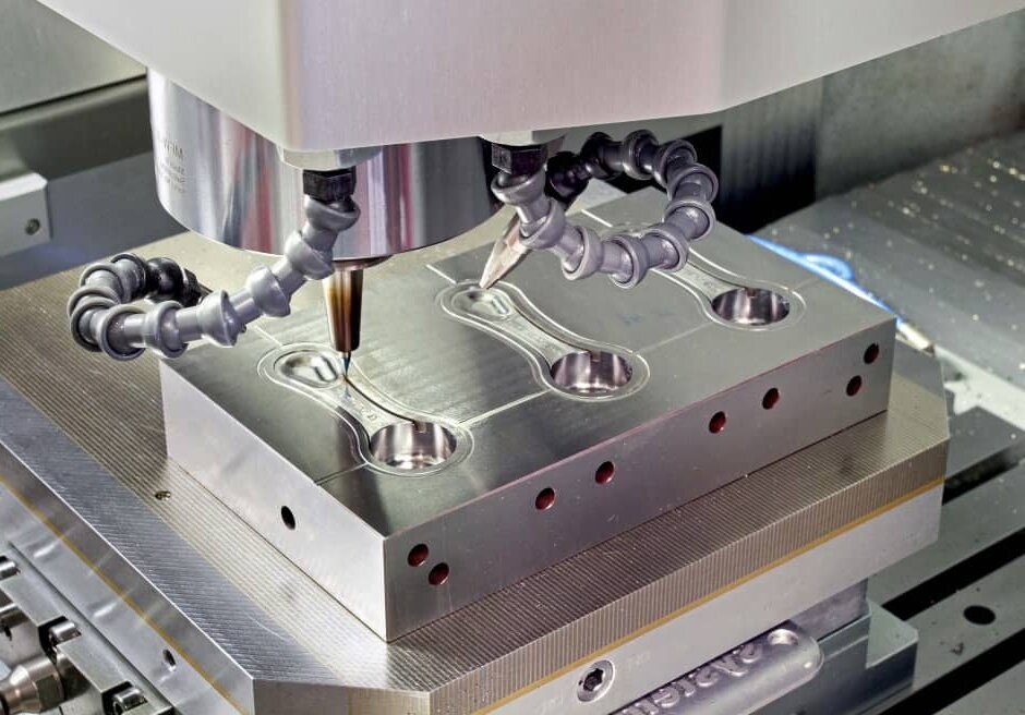
Directly milling hardened tool steels (typically above 45 HRC) is common in mold making and precision components. HSM can often reduce or eliminate the need for subsequent electrical discharge machining (EDM) or manual polishing.
This approach works well for open contours and shallow cavities. However, it remains limited by deep, narrow areas or sharp internal corners, where the cutter geometry cannot reach or clear chips effectively.
Complex Surfaces
For 3D contours, small details, and organic shapes, high feed rates paired with ball-nose end mills produce smooth surface finishes. To determine if this method is cost-effective, engineers must evaluate tool accessibility.
As a general rule of thumb, when the tool overhang exceeds 5x the tool diameter, the vibration at high speeds often negates the benefits of the process. This chatter forces a reduction in feed rates, eliminating the primary advantage of HSM.
| Machining Task[cite: 23] | Potential Gains[cite: 23] | Main Limits[cite: 23] | Alternatives to Compare[cite: 23] |
|---|---|---|---|
| Thin-Walled & Floor Parts[cite: 23] | Cuts cutting forces by up to 40%; keeps wall deflection within tight tolerances (e.g., ±0.02mm).[cite: 23] | Workpiece support, damping stress, and deformation after release.[cite: 23] | Different fixturing methods or altered machining sequences.[cite: 23] |
| Hardened Steel Contours[cite: 23] | Eliminates EDM time; achieves Ra 0.2 - 0.4 μm directly off the mill.[cite: 23] | Tool reach for deep cavities; sharp internal corner constraints.[cite: 23] | Conventional milling followed by EDM and hand polishing.[cite: 23] |
| Complex 3D Surfaces[cite: 23] | Cuts cycle times for organic geometries by 30-50% while maintaining surface finish.[cite: 23] | Tool accessibility; instability caused by long tool overhangs (>5x diameter).[cite: 23] | Alternative cutter geometries or splitting the part assembly.[cite: 23] |
| Simple Parts or Bulk Roughing[cite: 23] | Requires precise calculation; becomes more cost-effective at volume (e.g., >50 units).[cite: 23] | High setup and tooling costs; standard roughing often removes bulk faster.[cite: 23] | Conventional heavy milling or casting/extrusion for bulk shapes.[cite: 23] |
How Materials Change the Cutting Requirements?
Different materials impose specific constraints on high-speed machining. A cutting strategy that clears aluminum flawlessly will destroy a carbide tool instantly if applied to titanium.
Alliages d'aluminium
Materials like 6061-T6 and 7075-T6 are the ideal candidates for high-speed machining, but their primary bottleneck is chip evacuation.
Because the material is removed so rapidly, chips easily pack into the flutes of the cutter or the pockets of the workpiece. If high-volume coolant or air blast does not clear them instantly, the tool will recut the chips, which mars the surface finish and often snaps the end mill.
Hardened Steels
Machining tool steels (such as H13 or D2) above 45 HRC shifts the focus entirely to thermal management.
A common mistake is using standard flood coolant. Applying liquid coolant to coated carbide tools (like TiAlN) running at high speeds in hardened steel causes thermal shock, leading to micro-cracking on the cutting edge. Air blast is usually the correct choice here, allowing the advanced tool coating to absorb and dissipate the heat effectively.
Titanium and Stainless
While often grouped as “hard-to-machine,” Ti-6Al-4V and austenitic stainless steels (304, 316L) fail for completely different reasons.
Titanium has extremely poor thermal conductivity. Heat does not leave with the chip; it concentrates in the cutting zone and transfers directly into the tool. This requires strict radial chip thinning and high-pressure coolant (often >1000 PSI).
Stainless steel, conversely, work-hardens rapidly. Climb milling is mandatory here to ensure the chip starts thick and ends thin. If the tool rubs or dwells in a corner due to conservative feed rates, the material surface hardens. The next cutter pass will then strike a significantly harder surface, leading to rapid built-up edge (BUE) and tool failure.
| Material Grade & State[cite: 24] | Primary Difficulty[cite: 24] | Process Selection Basis[cite: 24] | Trial Cut Focus[cite: 24] |
|---|---|---|---|
| Al 6061-T6 / 7075-T6[cite: 24] | Chip packing and recutting.[cite: 24] | High RPM, aggressive feed rates, high-volume coolant.[cite: 24] | Ensure complete chip evacuation from deep pockets.[cite: 24] |
| Hardened Steels (>45 HRC)[cite: 24] | Tool edge wear; thermal shock.[cite: 24] | Light radial engagement, specialized coatings (TiAlN), air blast.[cite: 24] | Monitor tool wear and surface finish degradation.[cite: 24] |
| Titane (Ti-6Al-4V)[cite: 24] | Heat concentrates in the tool.[cite: 24] | Strict radial chip thinning, high-pressure coolant.[cite: 24] | Monitor spindle load and tool temperature.[cite: 24] |
| Stainless Steel (304 / 316L)[cite: 24] | Work hardening; built-up edge (BUE).[cite: 24] | Constant, uninterrupted feed rates; mandatory climb milling.[cite: 24] | Check for material welding to the cutting edge.[cite: 24] |
What Machines, Tools, and Fixtures Need to Control?
High-speed machining is a system-level process. Running advanced toolpaths on a machine lacking the necessary rigidity or control capabilities will only result in chatter and scrapped parts.
Spindle and Axes
A 20,000 RPM spindle means little without the dynamic stiffness to absorb high-frequency vibrations. Equally critical is axis acceleration (jerk control).
If the machine cannot physically accelerate fast enough to reach the programmed feed rate before hitting the next corner, the tool dwells. In materials like stainless steel, this immediate loss of speed ruins the part and the tool. The machine must maintain adequate torque and continuous motion across its entire working range.
Tool Assembly
At speeds exceeding 15,000 RPM, the tool assembly must act as a single, perfectly balanced unit. Total Indicator Reading (TIR), or runout, must remain absolute minimum—typically below 0.005mm.
Standard ER collets struggle to maintain this consistency at high speeds. Shrink-fit or hydraulic chucks are standard for HSM because they provide 360-degree concentric clamping. Tool overhang must also be kept as short as mathematically possible to prevent deflection.
Workpiece Support
While HSM generates lower overall cutting forces due to light radial engagement, fixturing must account for induced stress. If a thin-walled component is clamped with excessive force, it will cut perfectly in the machine but warp out of tolerance the moment it is released (spring-back).
To solve this, shops typically use a multi-stage approach: dégrossissage the part, unclamping it to release residual stress, and then gently re-clamping it for the final high-speed finishing pass. Vacuum chucks are also highly effective, providing uniform support without pinch points.
How to Set Parameters for Roughing and Finishing?
Setting parameters for high-speed machining requires calculating specific targets based on the tool and material, rather than guessing based on machine limits.
Speed and Feed
The starting point is determining the Surface Cutting Speed (Vc) and the Feed per Tooth (fz) recommended by the tooling manufacturer.
For example, machining Al 6061-T6 with a 10mm, 3-flute carbide end mill:
- Target Vc: 400 m/min
- RPM Calculation:
(400 x 1000) / (3.1416 x 10) = approximately 12,732 RPM - Target fz: 0.1 mm/tooth
- Feed Rate Calculation:
12,732 x 0.1 x 3 = approximately 3,819 mm/min
During initial trial cuts, an operator might adjust this slightly—perhaps to 12,000 RPM and 3,500 mm/min—to avoid the specific resonant frequencies of that particular machine setup.
Roughing Strategy
Modern roughing relies on adaptive clearing or trochoidal milling to control the engagement angle. By maintaining a constant, light radial width of cut, the tool never experiences load spikes in corners.
Crucially, when the radial step-over drops below 50% of the tool’s diameter, a phenomenon called amincissement radial des copeaux occurs. The actual chip thickness becomes smaller than the programmed feed per tooth. Programmers must mathematically increase the feed rate to compensate—this chip thinning effect is exactly how HSM achieves such staggering feed rates without snapping tools.
Finishing Strategy
Finishing requires a completely separate setup. The goal shifts from bulk removal to dimensional accuracy and specific surface roughness (Ra).
This requires leaving a precise, consistent stock allowance (e.g., 0.1mm) during the roughing phase. The finishing pass then uses a calculated step-over based on the required scallop height. Attempting to use a single tool and a single set of parameters for both heavy roughing and precision finishing always compromises part quality.
Process Adjustment Example:
Consider an aerospace aluminum bracket previously roughed using a 12mm tool with heavy, slow cuts taking 45 minutes. By switching to an 8mm tool using an adaptive clearing strategy (deep axial cuts, light radial step-over, high feed to exploit chip thinning), the cycle time dropped to 18 minutes. The resulting wear and exact cost savings are evaluated in the next stage.
How to Troubleshoot Defects and Verify Results?
When a high-speed process fails, it happens quickly. Correcting the issue requires a methodical check of the mechanical setup before altering the CAM parameters or G-code.
Chatter Marks
Chatter is vibration imprinted onto the part. It typically manifests as vertical banding in corners, swirl marks at the bottom of deep cavities, or a “screaming” sound during thin-wall passes.
The first adjustment is never a blanket reduction in spindle speed. First, verify the tool overhang; even a 2mm excess can cause severe resonance. Second, check the workholding for flex. If both are rigid, you must tune the spindle RPM—either slightly up or slightly down—to find a stable harmonic zone. Blindly slowing down often keeps you in the chatter zone while killing your feed rate.
Usure des outils
In high-speed milling, tools should wear predictably along the flank. If you observe micro-chipping on the cutting edge, the tool is likely suffering from thermal shock (often from using liquid coolant on hardened steel) or excessive runout in the tool holder.
If you see aluminum welded to the flutes (built-up edge, or BUE), chip evacuation has failed. This usually means the coolant pressure is too low, or the tool is recutting chips trapped in a pocket. Document exactly where the wear occurs—corner radius, leading edge, or flute—to determine if the toolpath strategy or the coolant delivery needs adjustment.
Part Inspection
Verifying an HSM part goes beyond placing it on a CMM (Coordinate Measuring Machine).
Crucially, metals expand under machining heat. Never inspect an HSM part immediately after it comes off the machine. The part must soak to standard metrology ambient temperature (20°C / 68°F), or your tight-tolerance readings will be entirely false once the metal cools. Additionally, you must measure the part après it is released from the vise to check for spring-back distortion. A properly executed HSM finishing pass should also yield a nearly burr-free edge, proving the cutting forces were perfectly balanced.
| Defect Symptom[cite: 25] | Priority Check[cite: 25] | Adjustment Direction[cite: 25] | Méthode de vérification[cite: 25] |
|---|---|---|---|
| Corner Chatter[cite: 25] | Axis acceleration drop; tool overhang.[cite: 25] | Adjust CAM corner feed optimization; seat tool deeper in holder.[cite: 25] | Run a test contour; check visually for vertical banding.[cite: 25] |
| Edge Chipping[cite: 25] | Coolant type (thermal shock); tool holder runout.[cite: 25] | Switch to air blast (for hard metals); check TIR with a dial indicator.[cite: 25] | Inspect tool edge under magnification after 10 passes.[cite: 25] |
| Dimensional Warp[cite: 25] | Clamping stress (vise pressure); part temperature.[cite: 25] | Add a stress-relief roughing pass; let part soak to 20°C before CMM.[cite: 25] | CMM inspection while clamped vs. undamped.[cite: 25] |
| Built-Up Edge (BUE)[cite: 25] | Chip evacuation; dwelling.[cite: 25] | Increase coolant pressure; ensure continuous climb milling.[cite: 25] | Inspect flutes for welded material; check part for galling.[cite: 25] |
How to Compare Costs, Lead Times, and Quotes?
A faster cycle time does not automatically mean a cheaper part. Purchasing managers and engineers must evaluate the total cost of the manufacturing process to determine if HSM makes financial sense for their specific order.
Total Part Cost
Evaluating quotes based purely on “machine time” is a common trap. HSM drastically reduces cycle time but increases front-end costs. You must compare the CAM programming time, the cost of specialized workholding, the machine hourly rate (which is higher for dynamic spindles), and premium balanced tooling.
However, HSM often eliminates expensive post-processing. If an HSM process costs 10 more in tooling but saves 20 in manual deburring and EDM time, the total part cost drops. Furthermore, eliminating secondary setups drastically improves Spindle Uptime and overall equipment effectiveness (OEE).
Quantité et délai d'exécution
Preparation costs (advanced CAM programming and custom fixtures) must be amortized over the order quantity. For a single prototype, standard roughing is often cheaper because the programming is fast. For a batch of 50 units or more, HSM becomes highly competitive.
Lead time must also be viewed holistically. While HSM cuts the actual machining cycle, the true lead time advantage comes from skipping secondary operations. A part that comes off the mill completely finished bypasses the queue for the polishing or EDM department, shaving days off the total delivery schedule.
Supplier Evidence
When requesting quotes, provide the exact CAD revision, material grade and temper (e.g., Al 6061-T6 vs. T4), order volume, critical tolerances, and required Ra finish.
In return, purchasing managers should look for specific evidence from the supplier. Ask for their specific machining routing to verify if they intend to use EDM or direct hard-milling. For high-volume orders, ask for a Process Capability (Cpk) report on critical dimensions. A true HSM supplier will have the thermal stability and tool wear management to maintain a Cpk > 1.33 over hundreds of parts.
| Cost Factor[cite: 26] | Traditional Routing (500 units)[cite: 26] | HSM Routing (500 units)[cite: 26] |
|---|---|---|
| Setup & CAM Prep[cite: 26] | 2 hours ($150 total)[cite: 26] | 4.5 hours ($350 total)[cite: 26] |
| Machine Cycle Time[cite: 26] | 45 minutes / part[cite: 26] | 18 minutes / part[cite: 26] |
| Machine Rate[cite: 26] | $60 / hour ($45.00 / part)[cite: 26] | $75 / hour ($22.50 / part)[cite: 26] |
| Coût de l'outillage[cite: 26] | $2.00 / part[cite: 26] | $8.00 / part[cite: 26] |
| Post-Processing (Deburr/EDM)[cite: 26] | $3.00 / part[cite: 26] | $0.00 (Finished on machine)[cite: 26] |
| Total Cost Per Part[cite: 26] | $50.30 (+$0.30 setup amortized)[cite: 26] | $30.50 (+$0.70 setup amortized)[cite: 26] |
| Total Production Time[cite: 26] | ~47 days (includes secondary queues)[cite: 26] | ~20 days (direct to QA)[cite: 26] |
Ready to see if your components can benefit from high-speed machining? Submit your 3D CAD files, material requirements, and critical tolerances to Shengen today for a comprehensive DFM review, routing assessment, and production quote.
Hey, je suis Kevin Lee

Au cours des dix dernières années, j'ai été immergé dans diverses formes de fabrication de tôles, partageant ici des idées intéressantes tirées de mes expériences dans divers ateliers.
Prendre contact
Kevin Lee
J'ai plus de dix ans d'expérience professionnelle dans la fabrication de tôles, avec une spécialisation dans la découpe au laser, le pliage, le soudage et les techniques de traitement de surface. En tant que directeur technique chez Shengen, je m'engage à résoudre des problèmes de fabrication complexes et à favoriser l'innovation et la qualité dans chaque projet.
Ressources connexes
Matériaux de prototypage : comment choisir le bon matériau
Assemblage par emboutissage de la tôle : conception, coût et qualité