Cast aluminum involves pouring molten aluminum alloys into precision molds to produce complex, near-net-shape components. Highly valued for its exceptional strength-to-weight ratio and thermal conductivity, this process minimizes post-machining costs while delivering lightweight, corrosion-resistant parts for automotive and aerospace sectors.
This approach usually becomes more cost-effective at volume compared to machining parts from solid billets. However, casting is not a perfect process and comes with specific physical limitations. Engineers and buyers must account for inherent gas porosity, looser dimensional tolerances, and the reality that most precision mating surfaces will still require secondary CNC machining.
This guide outlines process selection, design for manufacturing (DFM) rules, alloy properties, and defect control to help you determine if aluminum casting aligns with your production needs.
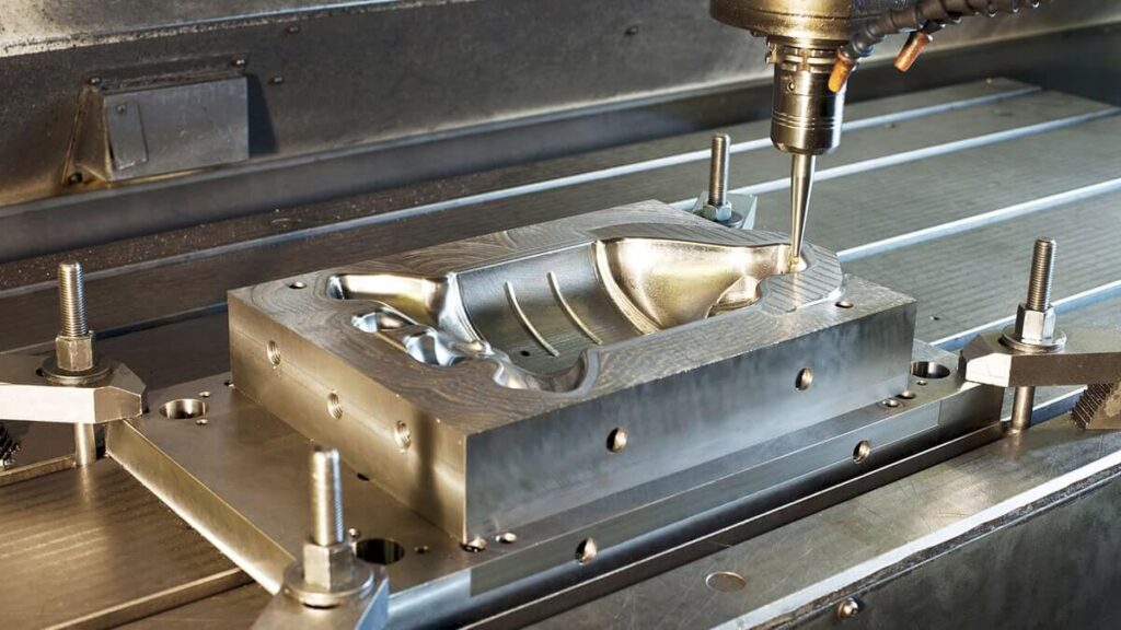
Where Cast Aluminum Works Best in Production?
Before evaluating specific casting methods, it is necessary to confirm if casting is the right manufacturing route for your part. The decision usually depends on production volume, part complexity, and mechanical requirements.
Volume Production
The primary financial driver for cast aluminum is production volume. Casting requires an upfront investment in tooling (molds), which can be substantial for methods like high-pressure die casting.
Casting becomes viable when the production volume is high enough to amortize this tooling cost. Typically, when volumes exceed a few thousand units, the per-part price drops significantly below that of CNC machining, making the initial tooling investment worthwhile.
Complex Geometry
Cast aluminum works well for parts with internal cavities, complex organic shapes, or varying wall thicknesses. Machining these features from a solid block often results in heavy material waste and long, costly machine run times.
Casting forms the near-net shape directly. This makes it an efficient way to produce components like engine housings, heat sinks, and pump bodies, where material removal would otherwise be highly inefficient.
Weight Reduction
Aluminum naturally offers a favorable strength-to-weight ratio. When combined with casting, engineers can design hollow structures and thin-walled sections that reduce overall part weight without sacrificing structural integrity.
This characteristic is widely utilized in the automotive and aerospace sectors. By optimizing wall thicknesses, manufacturers can meet strict fuel efficiency and payload requirements.
Mechanical Limits
While cast aluminum is structurally sound for many applications, it has defined limits. The casting process inherently introduces microscopic porosity and a less uniform grain structure compared to forged or extruded aluminum.
If a part operates under extreme tensile stress, severe impact, or high-cycle fatigue, casting may cause premature failure. In those specific load cases, wrought aluminum or steel is typically required.
Choosing the Right Aluminum Casting Process
If cast aluminum is suitable for your part, the next step is selecting the specific casting method. This decision depends on your budget, required tolerances, surface finish needs, and production volume.
Process Comparison Overview
| Process | Upfront Tooling Cost | Surface Finish (Ra) | Typical Tolerances | Target Volume | Min. Wall Thickness |
|---|---|---|---|---|---|
| High Pressure Die Casting | Very High | 1.6 - 3.2 μm | ± 0.1 mm | 10,000+ | ~1.5 mm |
| Sand Casting | Low | 6.3 - 25 μm | ± 0.7 mm - 1.5 mm | 1 - 1,000 | ~3.0 mm |
| Investment Casting | Moderate | 1.6 - 3.2 μm | ± 0.13 mm | 100 - 5,000 | ~1.5 mm |
| Gravity & Low Pressure | Moderate to High | 3.2 - 6.3 μm | ± 0.3 mm - 0.5 mm | 1,000 - 10,000 | ~3.0 mm |
High Pressure Die Casting (HPDC)
High pressure die casting forces molten aluminum into a steel mold at high speed and pressure. It allows for rapid cycle times and thin wall sections, making it the standard choice for high-volume production where low piece prices justify the expensive steel tooling.
However, the turbulent flow of the metal often traps air, leading to internal gas porosity. Because of this trapped gas, HPDC parts generally cannot undergo high-temperature heat treatments (like T6) without risking surface blistering.
Sand Casting
Sand casting uses a disposable sand mold formed around a pattern. It has the lowest tooling cost and is highly scalable in terms of part size, accommodating everything from small brackets to massive engine blocks weighing several tons.
The trade-off is a rough surface finish and wider dimensional tolerances. It is primarily used for prototyping, low-volume production runs, or exceptionally large parts where metal tooling would be impossible or too costly.
Investment Casting
Also known as lost-wax casting, this process uses a wax pattern coated in a ceramic shell. Once the wax is melted out, molten aluminum is poured into the shell to form the part.
Investment casting produces excellent surface finishes and tight tolerances, and handles complex internal undercuts exceptionally well. Because it is a slower, multi-step process, the per-part cost is higher, making it suitable mainly for high-precision industries like aerospace or medical equipment.
Gravity & Low Pressure Casting
Instead of high speed and high pressure, these methods use gravity or low, controlled pressure (typically under 1 bar) to fill the mold. The slower, more laminar flow of the molten metal significantly reduces gas entrapment.
Because the internal structure is denser and relatively free of porosity, parts made with these methods can undergo T6 heat treatment to improve mechanical strength. They are commonly specified for structural automotive parts, such as suspension components, where safety and strength are critical.

DFM Rules That Reduce Casting Defects
A significant portion of casting defects originates in the design phase rather than on the factory floor. Following basic Design for Manufacturing (DFM) rules ensures the molten aluminum flows predictably and solidifies evenly.
Wall Thickness
Maintaining uniform wall thickness is the most critical rule in casting design. When a part features thick sections connected to thin sections, the thinner areas cool and solidify first, blocking the flow of liquid metal to the thicker areas as they shrink.
This uneven cooling consistently leads to internal shrinkage voids. If varying thicknesses are unavoidable, engineers must design gradual transitions. For most high-pressure die casting projects, keeping wall thickness between 1.5 mm and 3.0 mm yields the most stable results.
Draft Angle
Vertical walls perpendicular to the parting line require a draft angle to allow the part to release from the mold. Without sufficient draft, the aluminum will scrape against the steel tool during ejection, causing surface galling and damaging the mold over time.
As a standard engineering practice, internal cavities require more draft than external walls because the aluminum shrinks onto the tool core as it cools. A typical baseline is 1° to 2° for internal features and 0.5° to 1° for external surfaces, though deeper draws will require larger angles.
Rib Design
When a part requires additional structural strength, increasing the overall wall thickness is usually the wrong approach, as it invites shrinkage defects. Instead, engineers should use a network of ribs to increase stiffness while maintaining a thin baseline wall.
To prevent sink marks on the opposite, visible surface of the part, rib thickness must be controlled. The thickness of a rib at its base should generally not exceed 60% of the thickness of the adjoining wall, and the rib should include generous root radii (fillets) to reduce stress concentration.
Machining Allowance
Casting cannot hold the tight tolerances required for bearing fits, sealing surfaces, or precision mating threads. These specific features must be machined into the cast part during a secondary CNC operation. Engineers must leave extra material, known as a machining allowance, on these surfaces.
Typically, adding 1.5 mm to 3.0 mm of stock is sufficient. When designing this allowance, engineers should practice “metal safe” design. It is relatively cheap to machine away tooling steel (which adds material to the cast part) if dimensions need tweaking later. However, welding steel back onto the mold (to reduce part thickness) is expensive, difficult, and reduces tool life.

Common Defects in Cast Aluminum Production
Even with optimized designs, the casting process is susceptible to specific physical defects. Understanding what goes wrong during production helps procurement and engineering teams set realistic quality acceptance criteria.
Gas Porosity
Gas porosity occurs when air or lubricating gases become trapped in the molten aluminum during the injection phase. It appears as small, spherical voids inside the material and is especially common in high-pressure die casting due to the turbulent flow of the metal.
While minor internal porosity is acceptable for non-structural parts, it becomes a severe issue for fluid-handling applications. The true cost of gas porosity is often hidden: it typically remains unseen under the dense outer skin of the casting, only to be exposed during secondary CNC machining. This results in scrapping a part after both casting and machining costs have already been incurred.
Shrinkage
Unlike gas porosity, shrinkage voids are irregularly shaped cavities caused by the natural volume reduction of aluminum as it cools from a liquid to a solid state. They typically form in the thickest sections of a part that solidify last.
Severe shrinkage compromises the mechanical integrity of the casting. The primary defense against this defect is strict adherence to uniform wall thickness during the DFM phase, allowing the foundry to design a cooling channel layout that promotes directional solidification.
Hot Tearing
Hot tearing refers to cracks that form in the casting while the metal is still at a high temperature and relatively weak. As the aluminum cools, it contracts; if the mold geometry severely restricts this natural contraction, internal stresses build up and tear the metal apart.
These cracks almost always initiate at sharp internal corners where stress concentrates. Replacing sharp 90-degree corners with generous radii (fillets) allows the stress to distribute evenly and helps the part survive the cooling phase intact.
Surface Blistering
Surface blistering is a specific defect that usually appears during secondary thermal processes, such as T6 heat treatment or powder coating curing. If a part has near-surface gas porosity, the trapped air expands when heated, pushing the softened aluminum outward and forming a blister.
This is the primary reason standard HPDC parts are rarely subjected to high-temperature heat treatments. For parts that must be powder coated, foundries must tightly control the injection parameters to minimize near-surface porosity, or transition to a gravity casting method.

Choosing the Right Cast Aluminum Alloy
Material selection in casting differs from machining. Engineers must balance the final mechanical requirements of the part with the “castability” of the alloy—how well the liquid metal flows and fills the mold.
A380 / ADC12
A380 (closely equivalent to ADC12) is the standard workhorse alloy for high-pressure die casting. It contains a high silicon content, which gives the molten metal excellent fluidity and reduces hot tearing during solidification.
It offers a solid balance of mechanical strength, low cost, and ease of casting, making it the default choice for electronic housings and brackets. However, designers must note: due to its high silicon content, A380/ADC12 is notoriously difficult to anodize cosmetically (it typically turns a patchy dark grey). If a decorative finish is required, engineers should specify powder coating or transition to a different alloy.
A356 / A357
A356 and A357 have lower silicon content and are primarily used in gravity, low-pressure, and sand casting processes. Their key advantage is that they respond exceptionally well to T6 heat treatment, which significantly increases their yield strength.
Because of this high strength and excellent elongation, these alloys are usually specified for structural and safety-critical applications. Typical uses include automotive alloy wheels, suspension knuckles, and aerospace housings.
A360
A360 features a slightly higher magnesium content and lower silicon compared to A380. This composition makes the alloy inherently more difficult to cast, requiring tighter process control on the foundry floor.
However, the trade-off yields superior corrosion resistance and better ductility. A360 is frequently chosen for parts exposed to harsh environments, such as marine hardware, outdoor telecom enclosures, and specific automotive fluid pumps.
Production Costs Beyond the Casting Process
Casting provides the near-net shape of a part, but it is rarely the final step. Understanding these downstream processes is necessary to calculate the true total cost of ownership (TCO) for a cast part.
CNC Machining
Casting cannot achieve the precision needed for functional mechanical interfaces. Features like threaded holes, O-ring grooves, and tight-tolerance bearing seats almost always require secondary CNC machining.
This requirement adds fixture design and machine run time to the total cost. To minimize these costs, engineers should design clear, cast-in datum targets (reference points). This simplifies custom fixture design and prevents tolerance stacking during secondary CNC setups. Buyers must accurately account for these operations when comparing the price of a cast part against a component machined entirely from a solid billet.
Surface Finishing
A raw cast part has visible parting lines, gate marks, and a generally dull appearance. At a minimum, parts require mechanical trimming, vibratory tumbling, or shot blasting to remove sharp edges and casting flash.
If the part requires environmental protection or a specific cosmetic appearance, further treatments like chemical conversion coatings, e-coating, or powder coating are necessary. Each of these surface preparation and coating steps adds handling time and increases the final per-unit price.
Vacuum Impregnation
As discussed earlier, internal micro-porosity is a natural byproduct of the casting process. For components designed to hold fluids or pressurized gases, such as pump housings or pneumatic manifolds, even microscopic pores can cause pressure leaks.
To solve this, manufacturers use vacuum impregnation. This batch process forces a specialized liquid resin deep into the micropores, which then cures to permanently seal the part. While highly effective at preventing leaks, it adds specific processing costs and extends production lead times.
Scrap Rate
No manufacturing process yields 100% perfect parts, and casting is more susceptible to physical variation than pure CNC machining. Foundries calculate an expected scrap rate into their pricing models based on the part’s complexity and the strictness of the quality requirements.
If a part’s design is inherently difficult to cast, the foundry will factor a lower projected yield rate directly into the initial piece price. Adhering to strict DFM practices and setting realistic tolerance requirements are the most effective ways to secure a competitive quote and keep the actual scrap rate low.
How Manufacturers Control Casting Quality?
To maintain stable mass production and control the scrap rate, modern foundries cannot rely on guesswork. They utilize a combination of software simulation and hardware interventions to monitor and control the thermodynamic variables of the casting process.
Mold Flow Simulation
Before cutting any steel for the mold, engineers use advanced simulation software to visualize exactly how liquid aluminum will fill the cavity. This allows them to analyze temperature gradients, predict where shrinkage will occur, and identify potential air traps.
By adjusting the gate locations and cooling channels in the software, foundries can solve major defect issues virtually. This preemptive engineering is critical for ensuring a successful T1 (first tooling) trial, drastically reducing time-to-market by eliminating the expensive, trial-and-error physical mold modifications of the past.
Vacuum Assistance
In high-pressure die casting, the mold cavity is initially filled with air that can get trapped by the incoming high-speed metal. Vacuum-assisted casting systems actively evacuate this air just milliseconds before the aluminum is injected.
This hardware intervention significantly reduces internal gas porosity. The resulting parts have a denser internal structure, are less prone to leaking, and have a much lower risk of surface blistering during subsequent powder coating operations.
X-Ray Inspection
Visual surface inspections cannot detect internal shrinkage voids or excessive porosity. To verify the internal integrity of a casting without destroying it, foundries rely on non-destructive testing, primarily 2D X-ray or 3D CT scanning.
These tools are heavily utilized during the first-article inspection (FAI) phase to validate the mold design. During mass production, manufacturers routinely X-ray sampled parts from each batch to ensure the internal structure remains safely within the specified engineering limits.
Process Stability
The quality of a cast part relies heavily on maintaining strict control over the physical variables on the foundry floor. A slight drift in molten metal temperature, mold cooling line flow, or injection speed can immediately cause a spike in part defects.
Modern foundries stabilize these variables through extensive automation. Robotic ladles pour exact volumes of metal, thermal control units regulate mold temperatures, and automated sprayers apply precise amounts of release agent, ensuring consistent output across thousands of production cycles.
Conclusion
Aluminum casting is a highly efficient manufacturing method when production volumes justify the initial tooling investment. Success depends on aligning the part design with the physical realities of the molten metal and carefully planning for the necessary secondary operations. By adhering to uniform wall thicknesses, planning for machining allowances, and understanding alloy limitations, engineers can design parts that are both cost-effective and structurally reliable.
If you are developing a cast aluminum part and want to avoid production risks, you can share your drawings with us. We can review the design, suggest process options, and help identify potential manufacturing issues before mass production.
FAQs
What wall thickness range is suitable for different cast aluminum processes?
High-pressure die casting (HPDC) handles thin sections well, typically down to 1.5 mm. Sand and gravity casting require thicker walls, usually starting around 3.0 mm, to ensure the slower-moving metal fills the mold before freezing. Regardless of the process chosen, keeping the wall thickness uniform across the part is critical to prevent shrinkage voids.
Why do cast aluminum parts develop porosity during production?
Gas porosity primarily occurs when air or vaporized mold lubricants get trapped in the molten aluminum during injection. This is highly common in high-pressure die casting due to the turbulent, high-speed flow of the metal. Vacuum-assisted casting and optimized mold venting are the standard engineering solutions to minimize this trapped gas.
Which casting process provides the best balance between cost and precision?
The answer depends entirely on production volume. For low to medium volumes (100 to 5,000 parts), investment casting offers excellent precision and surface finish without extreme tooling costs. For high volumes (10,000+ parts), high-pressure die casting provides tight tolerances (± 0.1 mm) at a very low per-unit cost, easily justifying the initial investment in a steel mold.
When is CNC machining necessary after aluminum casting?
Secondary CNC machining is strictly required whenever a part features precision mating surfaces, threaded holes, O-ring grooves, or bearing seats. No casting process can hold the tight tolerances required for these functional mechanical interfaces. Engineers must design a “machining allowance” (typically 1.5 mm to 3.0 mm of extra material) into these specific areas.
What causes shrinkage defects in cast aluminum parts?
Aluminum naturally loses volume as it transitions from a liquid to a solid. Shrinkage defects occur when thick sections of a part cool slower than the thinner surrounding areas. The thin areas freeze first, cutting off the flow of liquid metal to the thick areas. As the remaining thick material contracts, it leaves behind irregular internal voids.
Hey, I'm Kevin Lee

For the past 10 years, I’ve been immersed in various forms of sheet metal fabrication, sharing cool insights here from my experiences across diverse workshops.
Get in touch
Kevin Lee
I have over ten years of professional experience in sheet metal fabrication, specializing in laser cutting, bending, welding, and surface treatment techniques. As the Technical Director at Shengen, I am committed to solving complex manufacturing challenges and driving innovation and quality in each project.