Engineers often encounter problems when designing parts that need to fit together. If the clearance is too large, parts may feel loose, create noise, or wear out quickly. If the clearance is too small, the parts may be hard to assemble or even fail. To avoid these issues, engineers use standard fits. Fits define how tight or loose two parts should connect.
Choosing the right fit can help save time, reduce waste, and improve performance. Let’s examine the different types.
What is a Fit in Mechanical Assemblies?
Fits are an essential part of mechanical assemblies. They describe how two parts connect and work together, most often a hole and a shaft. The fit decides whether the parts move freely, lock tightly, or stay somewhere in between.
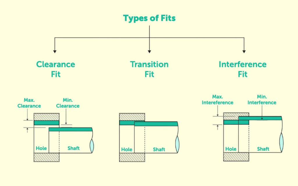
The classic example is a shaft inside a hole. If the hole is larger, the shaft can move. This is a clearance fit. If the shaft is larger, it presses into the hole. That is an interference fit. The fit may allow a small gap or slight pressure if the sizes are very close. This is a transition fit.
The right fit depends on the job of the parts. Bearings need clearance fits so they can rotate. Pressed gears need interference fits to stay fixed. Transition fits work well when parts must line up, but allow controlled assembly. Each type has a role, and the wrong choice can reduce strength, accuracy, or lifespan.
The Relationship Between Hole and Shaft Systems
Engineers use two central systems to apply fits: the hole and shaft systems.
In the hole system, the hole size stays fixed, while the shaft size changes to create different fits. This is the most common method because hole sizes are easier to control with standard tools.
In the shaft system, the shaft size stays fixed, but the hole size changes instead. This system is less common but useful when shafts must remain uniform across many uses. Both systems give engineers flexibility. They help balance manufacturing limits with performance needs.
The Role of Tolerances and Clearances
Tolerances set the allowed variation in part size. No part is made to an exact number, so tolerances define the maximum and minimum limits. These limits decide if parts will move, press, or align the way they should.
Clearance is the space between two parts. A positive clearance means the hole is larger, which allows movement or easy assembly. A negative clearance means the shaft is larger, which forces a tight fit. Transition fits can have either a small positive or negative clearance, depending on the measured sizes.
Types of Fits in Mechanical Assemblies
Choosing the right fit is an integral part of mechanical design. Each serves a specific purpose and comes with its own variations.
Interference Fit
An interference fit occurs when the shaft is larger than the hole. In this case, the parts must be pressed, heated, or cooled to fit together. Because of negative clearance, the surfaces push against each other, creating strong friction that prevents movement. This is why interference fits are also called press fits or friction fits.
A common way to achieve this is by press-fitting with mechanical or hydraulic force. Another approach is shrink-fitting, in which one part is heated or cooled temporarily to change its size. As the temperature returns to normal, the part locks firmly in place.
The tightness of an interference fit depends on the overlap, which usually ranges from -0.001 mm to -0.042 mm. Within this category, there are several levels:
- Press Fit – A lighter interference fit used for medium-strength joints.
- Driving Fit – A stronger fit that requires force or temperature methods to assemble.
- Forced Fit – The tightest form, usually permanent, demanding precise tolerances to avoid part damage.
Interference fits are ideal for gears, bushings, and heavy-duty joints that resist slipping even under vibration or load.
Clearance Fit
A clearance fit happens when the hole is larger than the shaft. This creates a small gap that allows the parts to move relative to each other. Because of the positive clearance, the assembly is easy and requires no special tools.
Clearance fits are useful in joints that require rotation, sliding, or free motion. For instance, the pin and frame in a pivot joint rely on clearance to allow rotation while staying connected. The clearance usually ranges from +0.025 mm to +0.089 mm.
Different subtypes allow for more control:
- Loose Running Fit – High clearance, giving parts noticeable play and easy movement.
- Free Running Fit – Similar to loose running but suitable for high speeds and thermal expansion. Accuracy is lower.
- Close Running Fit – Tighter clearance for better positioning while allowing high-speed movement.
- Sliding Fit – High precision, with minimal clearance that provides motion in only one direction.
- Location Fit – Very tight clearance for accurate alignment. Often requires lubrication for smooth operation.
Clearance fits are often used for bearings, pulleys, and couplings, where smooth movement and easy assembly are priorities.
Transition Fit
A transition fit sits between clearance and interference. Depending on the exact measurements, the parts may have a small gap or a slight overlap. This makes transition fits useful when parts must align accurately, allowing controlled assembly or disassembly.
The clearance range is typically +0.023 mm to -0.018 mm. Within this group, two common types exist:
- Similar Fit – Very light fit with almost no gap or interference. Assembly can often be done by hand with a soft mallet.
- Fixed Fit – Slightly tighter and usually requires pressing tools for assembly.
Transition fits are often used in machine components that need precise alignment without being completely permanent. They provide a balance between accuracy and ease of assembly.
| Type of Fit | Hole Basis | Shaft Basis | Fit Type | Applications |
|---|---|---|---|---|
| Clearance Fit | Hole size fixed, shaft made smaller | Shaft size fixed, hole made larger | Loose to free movement | Bearings, pulleys, sliding joints |
| Transition Fit | Hole size fixed, shaft slightly adjusted | Shaft size fixed, hole slightly adjusted | Near zero clearance, light press | Locating pins, couplings, machine alignment |
| Interference Fit | Hole size fixed, shaft made larger | Shaft size fixed, hole made smaller | Tight press, negative clearance | Gears on shafts, bushings, permanent joints |
Standards and Systems of Fits
They give engineers a common language for defining tolerances and fits. With these systems, designers avoid confusion, and manufacturers can deliver consistent, interchangeable parts.
ISO System of Limits and Fits
The ISO system is the most widely used standard worldwide. It defines fits using tolerance grades and fundamental deviations. A fit is written as a combination of a letter and a number. The letter shows the tolerance position, while the number shows the tolerance grade.
For example, H7/g6 describes a specific clearance fit between a hole and a shaft. Engineers use these codes to know how the parts will behave once assembled. The system also supports global trade because suppliers and manufacturers follow the same rules.
ANSI/ASME Standards
In the United States, engineers often follow ANSI and ASME standards. These systems serve the same purpose as ISO but reflect American design and manufacturing practices. They also use U.S. measurement units, which makes them more practical for local industries.
ANSI/ASME standards are common in aerospace, automotive, and heavy machinery fields. By applying these rules, companies ensure consistency from design to inspection. This makes assembling parts from different suppliers easier without a mismatch or error.
Hole Basis vs. Shaft Basis Systems
When applying fits, engineers choose between the hole basis system and the shaft basis system.
- In the hole basis system, the hole size stays fixed, and the shaft size is adjusted to create different fits. This method is the most common because hole dimensions can be controlled easily with standard tools like drills and reamers.
- In the shaft basis system, the shaft size stays fixed while the hole size is adjusted. This approach is less common but practical when shafts must remain the same size across many designs. For example, a company producing large batches of standard shafts may prefer to vary the hole sizes instead.
Key Factors for Choosing a Fit
When designing assemblies, engineers must consider how the parts will work, the loads they will face, and how they will be made. These points help decide whether a clearance, transition, or interference fit is correct.
Required Movement
The first question is movement. A clearance fit is usually best if parts need to rotate, slide, or adjust. It allows smooth motion with little resistance. Bearings and sliding guides are common examples.
A transition fit works well if parts must stay aligned but still allow some flexibility during assembly. It provides stability while keeping assembly possible. An interference fit is the most secure option for parts that must not move at all.
Load and Stress
The forces on the parts also guide the choice. Light loads often pair well with clearance fits, especially when smooth movement is needed. Heavy loads, shock, or vibration usually need interference fits. The tight lock prevents slipping and helps spread the stress.
Transition fits are a middle choice. They can handle moderate loads while keeping parts aligned. Material strength is also essential. Too much interference with weaker materials may cause cracks, bending, or lasting damage.
Production Method
The way parts are made affects which fit is practical. The whole basis system is the most common since standard tools make hole sizes easier to control. Using fits that match standard tooling for high-volume runs helps cut costs and improve efficiency.
Some processes, such as press or shrink fitting, are better for interference fits. Others, like reaming or grinding, can achieve the accuracy needed for transition fits. Engineers must select a fit that matches the design needs and the most efficient production method.
How to Achieve Dimensional Tolerances for Fits?
Getting tolerances right is the key to making fits work properly. Even small size changes can turn a clearance fit into an interference fit or cause parts to fail during assembly. Engineers and machinists use precise methods to control dimensions and keep parts within limits to prevent this.
One crucial step is choosing the proper machining process. Basic drilling or turning may not hold very tight tolerances. Processes like reaming, grinding, honing, or CNC machining are often used for closer fits. These methods reduce variation and give more consistent results.
Accurate measuring tools are also essential. Calipers, micrometers, and coordinate measuring machines (CMMs) check if parts meet the specified limits. Regular inspection during production helps catch errors early before they reach assembly.
Material selection matters as well. Some metals expand, shrink, or distort during machining or heat treatment. Engineers must account for these changes when setting tolerances to avoid fit problems later.
Practical Implementation and Best Practices
Engineers and machinists must apply these concepts correctly during design and production. Good drawing interpretation and awareness of common mistakes ensure smooth assembly and prevent costly rework.
Interpreting Engineering Drawings and Fit Callouts
Engineering drawings use codes to show fits. For example, a hole marked H7 paired with a shaft marked g6 defines a clearance fit. These notations come from standards like ISO or ANSI/ASME.
To read them correctly, engineers must look at the letter and the number. The letter shows if the size shifts above or below the base dimension, while the number defines how tight or loose the tolerance is. Machinists use this information to pick the proper machining process and inspection method.
Clear communication is essential. Designers, machinists, and inspectors must all follow the same standard system. Mixing different standards or misreading codes can lead to mismatched parts that will not fit together.
Common Pitfalls and How to Avoid Them
A frequent mistake is choosing a fit that is too loose or tight. This often happens when tolerances are not matched to the function or load. Engineers should always check the working conditions before making a selection.
Another issue is overlooking production limits. Some fits call for tolerances that are very costly or difficult to achieve. Choosing a fit that matches the available tools and processes saves time and money.
Material behavior is also easy to ignore. Heat, machining stresses, or surface finishes can change a part’s final size. Engineers must take these factors into account when defining tolerances.
Conclusion
Fits control how parts connect and move in mechanical assemblies. Clearance fits allow free movement, transition fits provide precise alignment with slight play, and interference fits create tight, secure connections. Engineers can design reliable, long-lasting products by understanding fits while avoiding assembly problems and costly errors.
Ready to get precise fits for your next project? Contact us today to discuss your design and manufacturing needs.
Hey, I'm Kevin Lee

For the past 10 years, I’ve been immersed in various forms of sheet metal fabrication, sharing cool insights here from my experiences across diverse workshops.
Get in touch
Kevin Lee
I have over ten years of professional experience in sheet metal fabrication, specializing in laser cutting, bending, welding, and surface treatment techniques. As the Technical Director at Shengen, I am committed to solving complex manufacturing challenges and driving innovation and quality in each project.


