CNC machining is a fast, accurate, and flexible process. But even small design mistakes can cause big problems. Parts with intricate shapes, tight fits, or hard-to-reach features often require more time to manufacture. They can also cost more and lead to quality issues. When engineers and designers miss these details, it can result in delays and extra tool wear.
Designing parts with machining in mind saves time, improves accuracy, and cuts costs. By carefully considering the geometry, wall thickness, holes, tolerances, material, and surface finish, you can make the part more straightforward to produce without compromising its strength or function.
Good design helps everyone involved — the designer, the machinist, and the end user. The sections below share simple ways to make CNC machining smoother and more predictable. The goal is to create parts that work well and are affordable to produce.
1. Optimizing Geometry and Features
Clever geometry design helps cut machining time and reduce tool wear. When you plan corners, cavities, and pockets carefully, you make parts easier and faster to machine.
Designing Internal Corners Wisely
Internal corners are common in many CNC parts, but sharp ones are particularly challenging to machine. Cutting tools are round, so they can’t create a perfectly sharp inside corner. If a design features sharp angles, the tool requires additional passes or smaller cutters, which increases both time and cost.
Adding fillets to internal corners is an easy way to improve machinability. The fillet radius should match or be slightly larger than the tool radius. For example, if you use a 6 mm end mill, a 3 mm internal fillet works well. This enables the tool to move smoothly, reduces vibration, and lowers the risk of tool breakage.
Fillets also make the part stronger. Sharp corners create stress points that can lead to cracks or fatigue. Rounded corners spread the stress evenly, which helps the part last longer.
Improving Cavity and Pocket Design
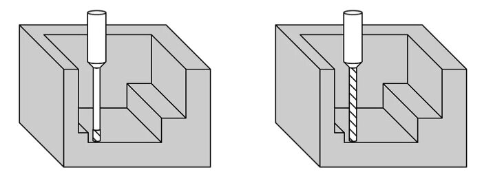
Cavities and pockets are often needed to reduce weight, fit assemblies, or hold components. However, deep or narrow cavities are more challenging to machine. When a tool penetrates too deeply into the material, it can bend, vibrate, or leave a rough surface.
To avoid this, try to keep the depth-to-width ratio of pockets low. A good rule is to keep the depth less than four times the tool diameter. For example, with a 10 mm cutter, avoid pockets deeper than 40 mm. If deeper cuts are required, you can split the depth into steps or redesign the part for easier access.
Whenever possible, use rounded bottom edges instead of flat ones. Flat-bottom cavities require special end mills, whereas rounded bottoms can be machined more efficiently with standard tools. Maintain a consistent wall thickness to prevent distortion or stress during machining.
Also, avoid sharp transitions inside pockets. Smooth slopes or ramped entries help spread cutting forces and remove material more efficiently. If the design allows, adding small draft angles can enhance tool access and chip removal, resulting in a smoother machining process overall.
2. Designing Efficient Walls and Ribs
The wall and rib design have a significant impact on CNC machining performance. Good design makes a part stronger, lighter, and easier to produce.
Finding the Right Wall Thickness
Wall thickness affects the strength and stability of a part during machining. Thick walls, waste material, and it takes longer to cut. Thin walls can bend or vibrate under the pressure of a tool. Both cases can cause poor tolerances, chatter marks, or rough surfaces.
The ideal wall thickness depends on the material and the size of the part. For aluminum, walls should generally be at least 0.8 mm thick for small parts and about 1.5 mm for larger ones. For stainless steel, aim for 1.0–2.0 mm thickness because it’s harder and resists cutting more effectively.
Maintaining a consistent wall thickness throughout the part helps prevent stress and distortion. Avoid sudden changes in thickness or long, unsupported walls. If the design needs thin areas, you can add ribs or flanges to support them. You can also reduce the machining depth in the regions that might flex excessively.
Strengthening Thin Walls for Better Machining
Thin walls help reduce weight, but they also make machining more difficult. When the tool pushes against a thin wall, the wall can bend slightly. This movement results in uneven cuts and additional finishing work. The goal is to design walls that are lightweight yet strong enough to withstand cutting forces.
Adding ribs is one of the best ways to reinforce thin walls. Ribs spread the stress and make the part stiffer without adding too much material. Place the ribs in the same direction as the main load and around areas that are likely to bend. As a guide, the rib thickness should be about 40%–60% of the wall thickness.
It’s also essential to connect ribs and walls with smooth fillets, rather than sharp corners. Sharp intersections create stress points that can lead to cracks or failure. Rounded transitions make the part stronger and easier to machine.
3. Mastering Hole and Thread Design
Hole and thread design have a significant effect on machining speed, tool life, and cost. Poor design can slow production and wear out tools faster. Good design, on the other hand, facilitates machining that is smoother, faster, and more accurate.
Using Standard Hole Sizes for Better Efficiency
Choosing standard hole sizes is one of the easiest ways to improve machining efficiency. Standard tools are easy to find, cost less, and reduce the need for tool changes. Non-standard sizes, even if slightly different, often require special drills or end mills. This incurs additional costs and setup time.
Whenever possible, use standard drill diameters like 1/8″, 1/4 “, 3/8”, or metric sizes such as 3 mm, 6 mm, and 10 mm. Sticking to these common dimensions enables machinists to use standard tools and program operations more efficiently.
Hole spacing also matters. Avoid placing holes too close to the edges or each other. A simple rule is to keep at least one hole diameter of space between the hole edge and nearby edges or holes. This helps prevent cracking, bending, or tool deflection.
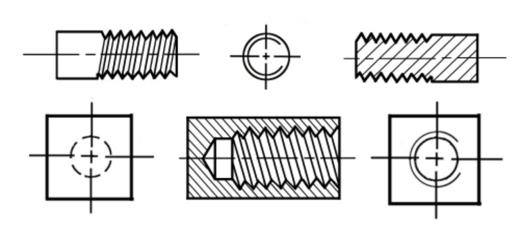
Threaded holes should also follow standard tap sizes. Keep the thread depth about 1.5 times the screw diameter for most metals. Making threads deeper doesn’t significantly increase strength, but it does make machining more difficult and increases the likelihood of tool breakage.
Making Holes Easy to Reach
Access to good tools saves both time and cost in CNC machining. When tools can’t reach holes directly, machinists often require extra setups or longer tools, which can compromise accuracy.
Design holes so that tools can enter straight from the top or side without obstacles. Avoid placing holes at odd angles or deep within narrow spaces unless necessary. If you must add an angled hole, include a flat surface for easier tool alignment.
Ensure there’s enough space around each hole for the tool to start and exit smoothly. Tight corners or nearby features can cause tool deflection or uneven holes. For deep holes, include relief areas or coolant paths to remove chips and control heat.
Also, avoid placing threaded holes too close to edges or thin walls, as this can compromise the part’s strength. Move them slightly inward or add extra support in that area. Adding chamfers at hole openings helps guide tools, protect threads, and improve assembly alignment.
4. Specifying Tolerances Wisely
Tolerances indicate the allowable difference between the design size and the actual machined part. Setting the right tolerances ensures high quality while minimizing extra costs.
Avoiding Unnecessary Tight Tolerances
Tolerances that are too tight are one of the biggest reasons for higher machining costs. Many designers use them by default, assuming tighter means better. In reality, excessive precision can slow down production and result in more rejected parts.
For most mechanical parts, a tolerance of ±0.1 mm (±0.004 in) is good enough. High-precision parts, such as bearing seats or press fits, may require a tolerance of ±0.01 mm (±0.0004 in), but only when the function truly necessitates it. By matching tolerances to the part’s purpose, you save time and reduce unnecessary machining work.
Every machining process has its own typical tolerance range. Milling, for example, can hold tighter tolerances than laser or plasma cutting. Choosing the correct tolerance for each process ensures consistent results and less rework.
Balancing Fit and Function
Good tolerance design is all about balance. Parts should fit together correctly, but still be affordable and easy to make. If the tolerance is too loose, the assemblies may move excessively. If it’s too tight, parts may not fit or could be damaged during assembly.
Consider how each part will function and interact with the others. Sliding fits need more clearance, while press fits require tighter control. For shafts and holes, use standard fits such as H7/G6 or H8/F7, based on the desired tightness or looseness of the connection. Standard-fit classes simplify production and ensure compatibility.
Always make your tolerance intent clear on the drawing. Mark only the critical dimensions that affect how the part works, and apply general tolerances to the rest. This helps machinists focus on the features that truly need precision, saving both time and cost.
5. Designing for Multiple Setups and Accessibility
Part accessibility is one of the most practical parts of CNC design, yet it’s often forgotten. A well-designed part enables machinists to easily access every feature, reducing the number of setups required.
Setting the Right Part Orientation
Good part orientation makes machining simpler and faster. When a part has transparent, open surfaces, it can often be finished in fewer setups. Each setup adds time and minor alignment errors, so reducing them improves accuracy and saves labor.
When designing, imagine how the part will sit on the machine bed. The best orientation should expose the most critical features of the tool in one setup. Flat surfaces are ideal for fixturing, so design stable bases that securely hold the part. If flipping is required, include alignment features or datums to help with accurate repositioning.
Try to avoid designs that need extreme tool angles or deep internal access. These usually require 5-axis machining or special fixtures, which increase cost. Keeping the design “flat” — with features reachable from standard 3-axis movement — makes machining more efficient and consistent.
Making Sure Tools Have Enough Access and Space
Tool access is a key factor in how easily a part can be machined—poor access forces machinists to use longer tools or complex toolpaths, which reduces precision and increases vibration. Designing with clear tool paths in mind ensures smoother cutting and better surface quality.
Always check if tools can reach internal or side features directly. If access is blocked, consider changing the design slightly. Adding chamfers, open slots, or access holes can give the tool room to start and exit cleanly.
Clearance is just as necessary. Ensure there’s sufficient space between walls, bosses, and cavities to prevent the cutting tool from colliding with the part or spindle. This is especially important in small-radius corners and deep pockets, where space is limited.
6. Selecting Appropriate Raw Materials
Material selection plays a significant role in machining speed, cost, and part quality. Choosing the right material early in the design stage can save hours of work and reduce waste.
Matching Material to the Part’s Purpose
Every part has a specific function, and that function determines which material works best. When designing, consider how the part will be used — the loads it will carry, the temperatures it will face, and the environment in which it will operate. These factors help narrow down the best material options.
For lightweight parts or prototypes, aluminum is often the top choice. It’s strong for its weight, easy to machine, and naturally resistant to corrosion. It’s also perfect for high-speed cutting. Stainless steel is better when the part must handle wear or harsh conditions, such as in marine or medical environments.
If you need high strength or heat resistance, titanium or alloy steels may be a better fit. However, they’re harder to machine and increase tool wear, which raises cost. For non-structural parts or prototypes, plastics such as ABS or POM are suitable. They’re easy to cut, lightweight, and provide electrical insulation.
Considering Machinability
Machinability refers to the ease with which a material can be cut and finished. It affects cutting speed, surface quality, and tool life. Materials that are too hard, sticky, or abrasive slow down machining and wear out tools quickly.
Aluminum and brass exhibit excellent machinability, producing smooth finishes with minimal effort. Mild steel also machines easily, but it requires coolant to control heat. Stainless steel, titanium, and hardened steels are tougher to work with. They generate more heat and friction, requiring slower cutting speeds or special tool coatings to prevent overheating.
When choosing materials, balance part performance with machining efficiency. Sometimes, a slightly more expensive material can be more cost-effective overall if it cuts faster and extends tool life.
7. Accounting for Surface Finish Requirements
Surface finish affects both the appearance and performance of a part. Planning the right finish helps meet both functional and visual goals without adding unnecessary cost.
Specifying Only What’s Necessary
Not every surface needs a perfect or shiny finish. Requiring fine surface roughness on all areas necessitates slower cutting speeds, specialized tools, and additional machining passes. This results in increased time and cost without a tangible benefit.
Focus only on the surfaces that truly need a fine finish. For example, bearing seats, sealing faces, or sliding areas should have smoother finishes. Non-contact surfaces can keep the standard marks left by cutting tools. Mark these crucial areas clearly on your drawings so machinists know where to focus their effort.
Balancing Looks and Performance
Some parts will be visible when assembled, so they need a clean and uniform look. Others are hidden and only need to function correctly. Match the finish to the part’s purpose.
Visible parts can utilize post-processing methods such as polishing, anodizing, or powder coating to achieve an attractive surface without requiring additional machining time. For functional areas, select finishes that enhance performance, such as reducing friction or facilitating assembly.
Avoid unnecessary polishing or grinding that doesn’t improve the part’s functionality. By balancing appearance with function, you maintain quality while keeping production efficient and affordable.
Ready to take your CNC designs to the next level? Our engineering team can review your parts and offer clear, practical advice to make them easier, faster, and more cost-effective to machine. Contact us today to share your project details and get a free consultation — let’s turn your ideas into high-quality, production-ready parts efficiently.
Hey, I'm Kevin Lee

For the past 10 years, I’ve been immersed in various forms of sheet metal fabrication, sharing cool insights here from my experiences across diverse workshops.
Get in touch
Kevin Lee
I have over ten years of professional experience in sheet metal fabrication, specializing in laser cutting, bending, welding, and surface treatment techniques. As the Technical Director at Shengen, I am committed to solving complex manufacturing challenges and driving innovation and quality in each project.
Related Resource

Fingerprint Resistant Stainless Steel: How It Works,and How to Choose


