Quality control is not a final inspection step — it is the mechanism that decides whether sheet metal parts perform correctly in the field. A part may pass basic measurement, yet warp under load, lose coating adhesion after three months, or cause a complete assembly misalignment. In real manufacturing, failures rarely originate at shipment; they typically originate upstream.
Sheet metal fabrication encompasses a range of processes, including cutting, bending, welding, forming, and finishing. Every stage introduces risk. Data from fabrication facilities indicate that addressing defects early is cost-effective — but correcting them after completion can be 10–20 times more expensive. Prevention always costs less than repair.
The foundation of any strong QC program lies in material verification and process-integrated control. When raw material quality is stable, and every manufacturing phase has checkpoints, quality becomes repeatable — rather than accidental.
Core Quality Control Framework in Sheet Metal Fabrication
A QC system must start before fabrication begins. Material variation directly affects formability, springback, weld penetration, corrosion behavior, and fatigue life.
Material Verification & Supplier Qualification
Material consistency is the first barrier against defects. Yield strength, thickness, hardness, and elongation must match engineering requirements — not approximations.
Typical material tolerance benchmarks:
| Parameter | General Tolerance | Precision Tolerance |
|---|---|---|
| Sheet thickness | ±0.05–0.10 mm | ≤±0.03 mm |
| Strength deviation | <5% from spec | <3% deviation |
| Surface finish condition | Minor marks acceptable | No defects in visible areas |
A supplier maintaining ±0.02 mm coil variation across three consecutive batches reduces incoming inspection workload by 40–60%. Certification alone is not enough — critical parts often require hardness sampling or tensile checks to verify actual mechanical behavior.
Failure case example
A stainless batch passed visual checks but had sulfur content 0.03% above tolerance. Six months later, weld toes cracked during wash-down cycles. Had metallurgical verification been included, failure would have been prevented.
Process-Integrated Quality Control During Production
Quality is created on the production floor — not at the end of it. A first article inspection validates bend angle, cut accuracy, and springback before full production begins. A bend tolerance of ±1° might look small, but it can shift hole patterns by 1.5 mm across a multi-fold enclosure.
Recommended production QC checkpoints:
| Stage | Critical Metrics | Risk If Unchecked |
|---|---|---|
| Cutting | Kerf width, burr, grain direction | Fit failure + tool wear escalation |
| Bending | Angle, springback, radius | Door/hinge misalignment |
| Welding | Heat input, bead uniformity | Frame warp + long-term cracking |
| Finishing | Coating thickness 60–90 µm | Rust creep or peeling |
A hold-point system — where production pauses until QC approval — typically reduces scrap 30–50% within 1–3 production cycles. Quality controlled early becomes quality protected later.
Inspection Methods, Weld Evaluation & Coating Performance Testing
Even with good material and process control, quality means nothing until it is measured. Inspection is not one tool — it is a layered system that validates geometry, weld integrity, coating durability, and surface condition. Reliable output requires all four.
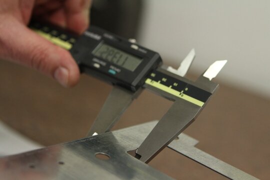
Dimensional Measurement & Tolerance Verification
Dimensional accuracy determines assembly success. Most software failures are not caused by a single significant error, but rather by several small ones that accumulate.
Typical measurement tools
- Vernier calipers, micrometers, pin gauges
- Height gauges for offsets and step levels
- CMM or laser scanning for complex geometry (±0.02–0.05 mm achievable)
Dimensional defects escalate quickly. A 1.2° bend angle deviation across multiple folds may cause more than 2 mm of displacement in the mounting hole, sufficient to cause hinge binding or panel vibration.
Recommended tolerance references
| Feature | Standard Target | High-Precision Target |
|---|---|---|
| Hole-to-hole spacing | ±0.10–0.15 mm | ≤±0.08 mm |
| Flatness (300–600 mm span) | ≤0.3–0.5 mm | ≤0.25 mm |
| Bend angle | ±1° | ±0.5° or lower |
If angles pass but flatness fails → springback + grain direction often the cause.
If spacing passes but fit-up fails → cumulative tolerance + alignment must be re-checked at the assembly level.
Surface Condition & Visual Quality Inspection
A part can be dimensionally correct yet still fail acceptance due to surface defects. Cosmetic criteria matter most for enclosures, door panels, covers, and customer-visible components.
Surface finish benchmarks
- Powder coat: Ra 1.6–3.2 μm
- Brushed stainless: Ra 0.4–0.8 μm
- Mirror-polish decorative panels: Ra ≤0.2 μm
Inspection should occur under 500–1000 lux diffused lighting to increase defect visibility by ~30%.
| Defect | Root Cause | Prevention |
|---|---|---|
| Waviness | Tool/die wear | Replace dies on schedule |
| Micro-dent | Handling damage | Use soft jaws + protective film |
| Coating pinholes | Oil contamination | Improve pre-treatment |
Surface QC is not aesthetic — it controls corrosion resistance, sealing performance, and customer perception.
Weld Integrity & Joint Verification
Welds determine structural survival.
A weld may appear smooth yet still fail in-service, especially when subjected to vibration in the 20–80 Hz range over time.
Tiered weld inspection approach
1) Visual weld acceptance
- No porosity clusters
- Undercut ≤10% of fillet size
- Uniform bead with clean toes
- No crater cracks or excessive heat tint
2) NDT methods for high-strength joints
| Method | Detects | Suitable For |
|---|---|---|
| Dye Penetrant (PT) | Surface cracks | Stainless → aluminum |
| Magnetic Particle (MT) | Subsurface cracks | Ferrous steels |
| Ultrasonic (UT) | Internal voids | High-load frames |
Ultrasonic scanning at 2–5 MHz detects a lack of fusion before cracks propagate, preventing field failure.
3) Mechanical validation
Proper fillet welds achieve 70–100% of the base metal’s strength.
If welds test below 60% → heat input, filler type, or fit-up must be corrected immediately.
Common failure pattern:
Too hot → distortion/warping
Too cold → brittle microfracture + loss of fusion
Coating Thickness, Adhesion & Corrosion Testing
Finishing is not just decoration — it is a layer of durability. Powder coating at 60–90 μm ensures corrosion protection without cracking.
Performance test references
- Cross-cut adhesion test: 1 mm grid spacing
- Salt spray:<240 hr → indoor use
- 480–1000 hr → industrial/outdoor grade
- Cross-cut adhesion test: 1 mm grid spacing
If adhesion fails, pretreatment is typically the root cause, not the coating.
Documentation, Traceability & Statistical Control
Inspection means nothing without repeatability. A factory becomes consistent when QC does not rely on individual operators.
ISO-driven workflows define
- How measurements are taken
- When corrective action triggers
- What data must remain traceable
SPC trend tracking prevents failures before they occur. If bending Cpk < 1.33, the process is not statistically stable → die wear or angle compensation must be adjusted.
Traceability enables root-cause accountability: If corrosion appears after six months, QC should know the coil batch, operator, shift, pretreatment bath, and bake curve.
High-performing factories miss failure — they predict it.
Assembly-Level Quality Control (QC)
Inspection does not end when a single part passes measurement. Absolute accuracy is confirmed only when components are assembled and function together as a whole. Tolerance stacking, weld shrinkage, and springback can turn a “correct” part into a failed assembly.
Small deviations compound. A panel only 0.3° out of bend angle may result in 1.6–2.2 mm hinge misalignment after four folds — enough to cause door drag, vibration, or interference during machine operation.
Assembly Fit Verification
The goal is to validate parallelism, twist, flatness, and hole alignment under real assembly pressure — not just on a drawing.
Assembly QC benchmarks
| Checkpoint | Recommended Target |
|---|---|
| Frame diagonal difference | ≤0.5–1.0 mm |
| Rail parallelism | ≤0.10–0.20 mm per 500 mm |
| Door/hinge clearance | Within ±0.5 mm |
| Fastener preload retention | ≤10–15% torque drop |
If flatness is correct individually but twist appears after bolting, the issue lies not in machining but in residual stress + uneven clamping.
Functional Load & Vibration Testing
Geometry shows the part’s shape. Load testing determines whether a system can withstand real-world stress.
Typical validation guidelines
| Component Type | Performance Requirement |
|---|---|
| Machine frame | <1.5 mm deflection at rated load |
| Structural sheet panels | 1.25–1.50× load test factor |
| Hinges / access covers | 50,000–100,000 cycle endurance |
| Welded structures | Tested under 20–80 Hz vibration |
If a panel passes dimensional QC but resonates within 60–80 Hz, micro-cracks may appear in weeks, not years. Assembly QC confirms not just fit, but survival in working conditions.
Long-Term Reliability Validation & Fatigue Behavior
Short-term inspection detects geometry. Long-term validation ensures that the product remains stable in real-life conditions. This is where many manufacturers stop — and where actual failure begins.
Environmental & Aging Simulation
Sheet metal products are susceptible to corrosion, thermal expansion, UV breakdown, and cyclic stress. These must be tested before delivery, not discovered in the field.
Accelerated reliability tests
- Salt spray 240–1000 hr, depending on the environment grade
- Thermal cycling 10°C ↔ 70°C (multi-round)
- UV exposure for outdoor powder-coated assemblies
- Vibration endurance testing for fatigue growth
When coating adhesion degrades during aging tests, edge creep and under-film corrosion are inevitable later.
Fatigue, Stress Relaxation & Residual Strain
Some failure modes are invisible at shipment — but fatal after usage.
Indicators of fatigue risk
- Cracks at weld toes or sharp bend radii
- Sheet buckling near high-stress load points
- Loosening fasteners after thermal cycling
Prevention techniques
| Failure Mode | Preventive Measure |
|---|---|
| Weld fatigue | Toe smoothing / heat control / gusseting |
| Bending crack growth | Increase bend radius + grain direction control |
| Bolt preload loss | Thread-locking + torque audit scheduling |
A bolt torqued at 25 Nm may drop to 15 Nm after heat cycling, creating movement even though the joint still “looks fine.”
Design-for-Inspection & Predictive Quality Intelligence
The best reliability does not come from more inspection, but from inspection-friendly design.
DFI strategies that cut QC time by 50–70%:
- Add datum tabs and probe surfaces
- Keep weld scan paths accessible
- Provide coating test patches near edges
- Avoid hidden internal joints when possible
Pair this with digital QC — including SPC, CPK trend monitoring, and automated vision detection — and the system begins predicting deviation before failure. High-maturity factories don’t detect problems. They foresee them.
Continuous Quality Improvement & Scalable Production Control
Quality is not a checkpoint — it is a system. Factories that only inspect parts react to problems. Factories that learn from inspection data prevent issues.
Root Cause Analysis & Corrective Actions
Repeating defects are not inspection mistakes — they are indicators of process instability. If bend deviation increases after 5,000 cycles, the problem is likely due to tool wear, rather than operator error. More inspection will not fix drift — corrective action will.
Effective RCA steps
| Stage | Objective |
|---|---|
| Identify recurring defect | Observe pattern, not symptom |
| Determine failure driver | Tooling / material / operator / heat control |
| Implement corrective action | Process change > manual rework |
| Validate recovery | Data must confirm improvement |
Closed-Loop Feedback: QC → Design → Production
Quality compounds when information flows backward. Dimensional inspection adjusts bend compensation. Weld distortion feedback improves fixturing strategy. Salt-spray failure drives pretreatment chemistry revision. This loop ensures that every subsequent production run is more stable than the previous one.
Factories that run closed-loop QC typically reduce scrap 20–50% within 3–6 months, even without new machinery, only by using data better.
Cost, Rework & Delivery Stability — The Real ROI of Quality
Quality reduces more than defects — it reduces lost capacity, lost time, and lost customers.
Reworking panels after coating can cost 10–20× more than fixing a bend angle during first-article validation. When defects survive to final assembly, delivery dates slip — and trust rarely recovers.
Scalable QC = Scalable Manufacturing Capability
A factory becomes scalable when its output is predictable. Standardized QC ensures repeatability across shifts, batches, and operators. Traceability accelerates investigation instead of guesswork. Predictive monitoring stops failure from leaving the building.
Conclusion
Material verification prevents defects at the source—process checkpoints to stop variation before it multiplies. Dimensional inspection proves geometry. Continuous improvement makes sound output predictable. Good parts are not luck. Good parts are designed, verified, tested, and continuously improved.
If you are optimizing your QC workflow, reducing rework, or improving weld/fit consistency, we can help. Send your drawings, tolerance requirements, or quality challenges to: sales@goodsheetmetal.com
We respond with actionable QC recommendations, manufacturability feedback, and improvement pathways tailored to your production reality.
FAQs
What is the acceptable tolerance in sheet metal fabrication?
±0.10–0.15 mm is standard for hole spacing, ±1° for bends. Precision enclosures may require a tolerance of ≤±0.08 mm and ±0.5° angle tolerance.
How do you test weld quality in metal fabrication?
Welds are evaluated using visual inspection, dye penetrant (PT), magnetic particle (MT), ultrasonic testing (UT), and mechanical shear testing.
What causes assembly misalignment even when parts measure correctly?
Tolerance stacking, springback, weld shrink distortion, and datum misreference are primary contributors.
How thick should powder coating be on metal parts?
Most industrial applications require a coating thickness of 60–90 μm. <60 μm increases corrosion risk; >100 μm increases chipping risk.
How do you prevent fatigue cracking in sheet metal structures?
Control weld heat input, increase bend radii, align grain direction, smooth weld toes, and validate under vibration at frequencies ranging from 20 to 80 Hz.
Hey, I'm Kevin Lee

For the past 10 years, I’ve been immersed in various forms of sheet metal fabrication, sharing cool insights here from my experiences across diverse workshops.
Get in touch
Kevin Lee
I have over ten years of professional experience in sheet metal fabrication, specializing in laser cutting, bending, welding, and surface treatment techniques. As the Technical Director at Shengen, I am committed to solving complex manufacturing challenges and driving innovation and quality in each project.
Related Resource

Fingerprint Resistant Stainless Steel: How It Works,and How to Choose


