In sheet metal fabrication, precision is not just a goal — it’s a requirement. A single misalignment of 0.2 mm can cause door panels to jam or electronic modules to misfit inside enclosures. Such small deviations often lead to rework, waste, and project delays.
Inspection tools ensure that every part, from a simple bracket to a complex chassis, meets its design intent. Today’s inspection process combines traditional measuring instruments with digital and automated systems that deliver real-time data and traceability.
According to industry surveys, early-stage inspection can reduce rework costs by 30–50% and improve on-time delivery rates by nearly 20%. That’s why leading manufacturers treat inspection as an investment — not an expense.
The Role of Inspection in Sheet Metal Production
Inspection is no longer a one-time quality gate at the end of production. It is a continuous verification process integrated into every stage — from raw material receiving to assembly and final finish.
The Purpose Behind Inspection
Every sheet metal part must match the 3D CAD model or drawing — dimensionally, functionally, and visually. This includes verifying hole diameters, bend angles, flatness, and coating thickness.
For instance, when producing a stainless-steel electrical cabinet, even minor angular deviation can prevent door alignment or gasket sealing. Adhering to ISO 9001:2015 and ISO 2768 standards ensures repeatable tolerance control and accurate documentation for every production run.
Beyond dimensions, inspection verifies weld quality, coating adhesion, and surface roughness — ensuring both structural integrity and appearance meet requirements.
When does the Inspection happen?
Inspection typically occurs in three major phases, each preventing a different kind of defect:
Incoming Material Inspection
Raw materials are checked for thickness, flatness, and composition before entering production. Example: An aluminum sheet labeled 5052-H32 must stay within ±0.05 mm thickness tolerance to ensure a consistent bending response.
In-Process Inspection
During cutting, bending, and welding, inspectors use calipers, angle gauges, and visual checks to confirm dimensions and features. Real-time inspection at this stage prevents costly rework downstream and helps adjust machine parameters before errors multiply.
Final Inspection
Completed assemblies undergo full dimensional and functional verification. Measurements are compared to the CAD model or GD&T callouts, and digital inspection reports are generated for traceability.
Many factories now issue Final Inspection Certificates (FICs), or First Article Inspection (FAI) reports, as part of customer QA documentation.
Inspection as Part of Quality Assurance (QA)
Inspection supports more than quality control — it strengthens the entire quality assurance ecosystem. By analyzing measurement trends statistically, engineers can identify tool wear, thermal drift, or material variation before they affect product quality.
Factories achieving Cpk values above 1.33 are considered capable of maintaining stable, repeatable production. This data-driven approach not only reduces variation but also drives continuous improvement and process predictability.
A well-implemented QA program can lower defect rates by over 25% while improving long-term customer satisfaction through consistent performance and documentation.
Traditional Measurement Tools That Still Matter
Even in the age of automation, traditional tools remain essential for quickly and reliably verifying dimensions on the shop floor. They provide tactile feedback and flexibility that automated systems often can’t match.
Calipers, Micrometers, and Height Gauges
- Vernier or digital calipers measure outer, inner, and depth dimensions with accuracy up to ±0.02 mm, ideal for sheet thickness or hole spacing.
- Micrometers deliver even finer precision (±0.005 mm) for critical dimensions like flange width or weld bead buildup.
- Height gauges used with granite surface plates ensure consistent feature heights and datums between batches.
In prototype environments, these instruments are often the first line of verification — fast, flexible, and affordable. However, consistent calibration and operator technique are vital to maintain measurement reliability.
Angle Finders, Radius Gauges, and Thickness Gauges
- Angle finders verify bending accuracy. For example, a 90° bend may allow a ±0.3° tolerance to ensure assembly fit.
- Radius gauges confirm edge and corner radii to prevent cracking or sharp transitions that could weaken the part.
- Thickness gauges — mechanical or ultrasonic — validate both raw sheet and coating thickness, ensuring compliance with drawing requirements.
These simple tools help maintain geometry control and reduce the risk of assembly misalignment or finish defects later in the process.
Surface Plates and Inspection Fixtures
A granite surface plate offers a flat, stable reference for dimensional checks such as flatness and parallelism. For thin laser-cut panels, this helps detect heat distortion or bowing that could affect subsequent bending or assembly.
Custom inspection fixtures or go/no-go gauges are also common in repetitive production. They allow quick verification of key dimensions (e.g., hole spacing or tab alignment) within seconds, reducing cycle time without compromising accuracy.
Efficiency Tip: Using dedicated fixtures for frequent checks can reduce inspection time per part by up to 60%, especially in high-volume cabinet or enclosure production.
Traditional Tool Comparison Table
| Tool Type | Typical Accuracy | Ideal Application | Cost Range | Inspection Frequency |
|---|---|---|---|---|
| Vernier Caliper | ±0.02 mm | General dimensions | $30–$150 | Daily / per batch |
| Micrometer | ±0.005 mm | Flange, thickness | $50–$250 | Weekly |
| Height Gauge | ±0.01 mm | Datum-based heights | $200–$800 | Monthly |
| Angle Finder | ±0.3–0.5° | Bend accuracy | $50–$200 | Daily |
| Radius Gauge | ±0.1 mm | Edge radius | $10–$100 | As needed |
| Thickness Gauge | ±0.01 mm | Sheet / coating check | $100–$500 | Each batch |
Advanced Dimensional Inspection Equipment
As sheet metal designs become more intricate — with tighter tolerances, curved surfaces, and complex assemblies — traditional gauges alone are no longer sufficient. Manufacturers now use advanced dimensional inspection systems that combine accuracy, speed, and data traceability.
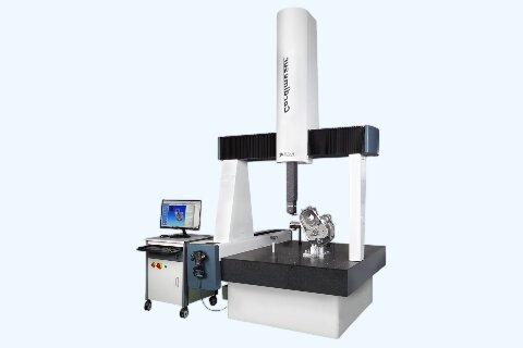
Coordinate Measuring Machines (CMMs)
A Coordinate Measuring Machine (CMM) is one of the most trusted tools for high-precision dimensional inspection. It uses mechanical probes or laser sensors to collect 3D coordinate data from key surfaces, edges, and holes.
Key Advantages:
- Achieves repeatability within ±0.002 mm, ideal for small parts or high-precision assemblies.
- Accurately measures flatness, perpendicularity, true position, and hole alignment.
- Generates automatic digital reports compatible with QA systems (ISO 9001 or AS9102 standards).
CMMs are especially valuable for aerospace, medical, and precision electronics enclosures, where part-to-part consistency is critical. Although initial investment is high, manufacturers typically recover the cost through reduced rework and faster first-article approvals.
ROI Insight: Replacing manual checks with CMM inspection can reduce total inspection time by 40–60%, particularly when inspecting multi-feature sheet metal assemblies.
Laser Scanners and Optical Profilers
Laser scanning has revolutionized sheet metal inspection by enabling non-contact, full-surface analysis. Instead of touching points individually, scanners project laser lines over the surface, capturing dense 3D point clouds that form a complete digital replica of the part.
Applications:
- Inspecting thin or flexible parts that deform under contact.
- Comparing formed parts against CAD models for springback analysis.
- Checking large panels, chassis, or enclosures without fixtures.
Performance Comparison:
| Method | Accuracy | Measurement Speed | Ideal Application |
|---|---|---|---|
| CMM | ±0.002 mm | 5–10 min/part | Small rigid parts |
| Laser Scanner | ±0.01 mm | <1 min/part | Thin or flexible panels |
| Optical Profiler | ±0.005 mm | <2 min/part | Surface roughness / coatings |
Vision Measurement Systems
Vision inspection systems integrate high-resolution cameras, lighting, and pattern-recognition software to evaluate 2D or 3D part geometry. They are especially efficient for flat sheet-metal parts, such as laser-cut blanks, perforated panels, and mounting plates.
Advantages:
- Captures multiple dimensions in seconds.
- Detects defects such as scratches, burrs, or edge distortion.
- Compares actual parts against stored “golden sample” templates.
For example, in energy storage enclosures, a vision system can verify hole alignment across 50+ points in under 10 seconds — a task that would take a technician several minutes with manual tools.
Thickness and Coating Gauges
Surface and coating inspections ensure that protection layers — such as zinc, nickel, or powder coating — meet required specifications. Too little coating reduces corrosion resistance; too much may affect assembly fit or grounding conductivity.
| Gauge Type | Principle | Common Use | Accuracy |
|---|---|---|---|
| Magnetic Induction | Measures magnetic flux in coatings on steel | Zinc, powder coating | ±1–3% |
| Eddy Current | Uses electromagnetic field variations | Anodized aluminum, copper | ±2–5% |
| Ultrasonic | Measures sound reflection time | Multi-layer coating / paint | ±1 µm |
In practice, many manufacturers use these gauges to confirm compliance with ISO 2178 and ISO 2360 coating thickness standards. For example, a zinc-coated steel bracket with a coating thickness of <8 µm may fail corrosion testing under ASTM B117 salt-spray exposure.
Specialized and Functional Testing Devices
Even if all dimensions are correct, a part can still fail in service due to poor welding, uneven coating, or misalignment. That’s why functional inspection tools play a vital role in verifying that every fabricated component meets both performance and safety standards.
Weld Inspection and Surface Roughness Testers
Weld quality directly affects the structural strength of sheet metal assemblies. Modern inspection uses both visual and instrument-based methods to detect defects like porosity, undercut, or incomplete fusion.
Common Techniques:
- Visual inspection: with magnifiers or digital microscopes for surface cracks.
- Dye penetrant testing (PT): reveals open-surface flaws on non-porous materials.
- Ultrasonic testing (UT): identifies internal discontinuities in welds or joints.
For surface quality, roughness testers (profilometers) measure Ra, Rz, and Rt values. A brushed stainless finish (Ra 0.8–1.6 µm) ensures coating adhesion and uniform reflection — critical for medical devices and consumer enclosures.
Flatness, Hole Alignment, and Assembly Jigs
Custom inspection jigs simplify repetitive checks for high-volume parts.
They allow quick verification of flatness, hole position, and mating accuracy without complex setup.
Example Use Cases:
- Checking cabinet door alignment within ±0.1 mm before powder coating.
- Verifying bracket hole positions across multi-part assemblies.
- Ensuring enclosure panels remain flat after welding and grinding.
Well-designed jigs can reduce inspection cycle time by up to 70% while maintaining repeatability across thousands of units.
Non-Destructive Testing (NDT) Methods
For critical components — such as structural frames, pressure housings, or mounting brackets — Non-Destructive Testing ensures internal integrity without damaging the part.
| Method | Detects | Common Materials | Typical Standard |
|---|---|---|---|
| Dye Penetrant (PT) | Surface cracks | Stainless, aluminum | ASTM E165 |
| Ultrasonic (UT) | Subsurface voids | Steel, aluminum | EN ISO 17640 |
| Magnetic Particle (MT) | Surface flaws in ferromagnetic metals | Carbon steel | ASTM E1444 |
| Radiographic (X-ray) | Internal weld quality | Thick welds, cast parts | ISO 17636 |
Although NDT adds cost, it is essential for applications in aerospace, automotive safety systems, and medical equipment, where part failure could have serious consequences.
Design for Inspectability (DFI) — Building Quality into Design
Most manufacturing problems start before the first part is even made — during design. When inspection is an afterthought, engineers spend more time struggling to measure parts than to improve them.
Making Parts Easier to Measure
Good design doesn’t just improve function; it also simplifies inspection.
Engineers can save hours of inspection time per batch by incorporating features that make measurement straightforward.
Effective DFI practices include:
- Adding datum holes, slots, or alignment pins for quick CMM or fixture setup.
- Keeping flat or accessible reference surfaces for calipers and probes.
- Maintaining consistent bend radii and hole spacing to reduce measurement variation.
- Avoiding hidden or obstructed features that complicate verification.
For example, adding two 6 mm datum holes in a bent panel allows inspectors to locate parts in seconds, reducing setup time by 40–50% compared to manual edge alignment.
Engineering ROI: A small CAD design adjustment can save up to 10 minutes of inspection time per part, translating to thousands of dollars in annual labor savings for mass-production runs.
Collaboration Between Design and Quality Teams
Design engineers and quality inspectors should collaborate early — before drawings are finalized.
Regular DFM (Design for Manufacturability) and DFI reviews ensure that features can be both produced and inspected efficiently.
Example:
If a bracket hole becomes inaccessible after the final bend, the design team can modify the folding order or add a verification cutout before release. These small changes prevent costly redesigns and avoid nonconforming parts during the first production run.
Cross-departmental collaboration also improves drawing clarity, ensuring that all GD&T symbols, datum hierarchies, and measurement points are properly defined for inspection reports.
Conclusion
Inspection is more than a technical procedure — it’s the foundation of quality, trust, and long-term partnership in sheet metal fabrication. From calipers to AI-driven scanners, every tool plays a role in ensuring that design intent becomes manufacturing reality.
Looking for a fabrication partner that guarantees precision and accountability? At Shengen, our engineers combine CMM, 3D scanning, and SPC-based QA to ensure every part meets your specifications — from prototype to production. Upload your CAD files today for a free manufacturability review and a sample inspection report.
FAQs
What are the most common inspection tools used in sheet metal fabrication?
Calipers, micrometers, height gauges, and angle finders are widely used for quick checks. Advanced systems include CMMs, 3D laser scanners, and vision measurement systems for high-precision and non-contact inspection.
How often should inspection tools be calibrated?
Calibration frequency depends on usage, but most precision tools require 6–12 month calibration cycles under ISO 17025 standards. CMMs and laser systems often need verification after every 1,000 working hours.
What’s the difference between Quality Control (QC) and Quality Assurance (QA)?
QC focuses on detecting and fixing defects, while QA builds systems that prevent defects from occurring — integrating inspection into every production stage for continuous improvement.
Why is “Design for Inspectability (DFI)” important in metal fabrication?
DFI ensures parts are easy to measure, reducing inspection time and human error. Designing with clear datums, accessible features, and consistent geometry enables faster setup and higher measurement accuracy.
Hey, I'm Kevin Lee

For the past 10 years, I’ve been immersed in various forms of sheet metal fabrication, sharing cool insights here from my experiences across diverse workshops.
Get in touch
Kevin Lee
I have over ten years of professional experience in sheet metal fabrication, specializing in laser cutting, bending, welding, and surface treatment techniques. As the Technical Director at Shengen, I am committed to solving complex manufacturing challenges and driving innovation and quality in each project.
Related Resource

Fingerprint Resistant Stainless Steel: How It Works,and How to Choose


