Making a functional sheet metal part takes careful planning. A well-designed part is strong, looks professional, and can be made without issues. This guide offers simple rules to help you design sheet metal parts that work in real production.
Design for Manufacturing (DFM) Principles
Good design makes production easier and cheaper. Always think about how the part will be made. This approach is called Design for Manufacturing, or DFM.
Importance of Tolerances in Fabrication
Tolerances set the allowed variation in a part’s dimensions. Only use tight tolerances where they are essential. Unnecessary tight tolerances drive up cost. For most features, stick to standard tolerances. This gives the fabricator room to work without lowering quality.
Keep Designs Simple
Simple parts are cheaper to produce. Reduce bends and unique features where you can. Let’s combine several parts into one. This lowers assembly time and reduces the need for fasteners. Simpler designs are also more reliable and easier to make.
Standardize Parts and Features
Use standard hole sizes, bend radii, and sheet sizes. Standardization cuts setup time and tooling changes. It also makes sourcing materials easier. Stick to common materials and finishes that are easy to get.
Common Features in Sheet Metal Parts
Sheet metal parts often include features that improve strength, function, or assembly. Each feature has a purpose and must be designed carefully to avoid problems during fabrication.
Corner Fillets
Sharp corners weaken parts and make bending harder. Fillets spread stress and lower the risk of cracks. They also improve fit during assembly and give a cleaner look. Use consistent radii that match standard tooling for easier production.
Ribs
Ribs add stiffness without much extra weight. They prevent warping in large, flat areas and reduce vibration. Keep rib depth and spacing uniform for better performance and easier manufacturing.
Embossments
Embossments create raised or recessed areas on the sheet. They can strengthen parts, act as spacers, or provide clearance for fasteners. Control the height and width to avoid tearing during forming.
Dimples
Dimples reinforce flat sections and can improve airflow in some designs. They also help align screws or rivets. Size them carefully to avoid thinning the material too much. Proper spacing ensures consistent strength across the part.
Round Knockouts
Round knockouts create openings for wires, cables, or fasteners. They can be removed without damaging the part. To prevent cracking, place knockouts away from bends or edges. Standard sizes work best for common hardware.
Louvers
Louvers provide ventilation while keeping parts strong and rigid. They guide airflow and can reduce weight. Set the right angle and spacing to balance airflow with strength. Please place them in flat areas to form cleanly and reduce defects.
Bending Basics
Bending shapes flat sheet metal into functional parts while keeping strength and accuracy. Understanding key terms and values makes designs easier to produce.
Bend Line
The bend line is where the sheet folds. Even a small shift can affect hole positions or assembly fit. A typical tolerance is ±0.25 mm, which keeps bends accurate for most parts.
Angle
The bend angle sets the final shape, like a 90° fold for brackets or frames. Materials such as mild steel often spring back 2–4° after bending. To achieve a true 90°, operators may set the tool to about 88°, allowing the part to relax into the correct angle.
Radius
The inside bend radius controls part strength. A good rule is to match the radius to the material thickness. For example, a 2 mm stainless steel sheet works best with a 2 mm inside radius. This prevents cracks and keeps bends smooth. Softer metals, like aluminum, can handle tighter bends, though matching thickness to radius improves consistency.
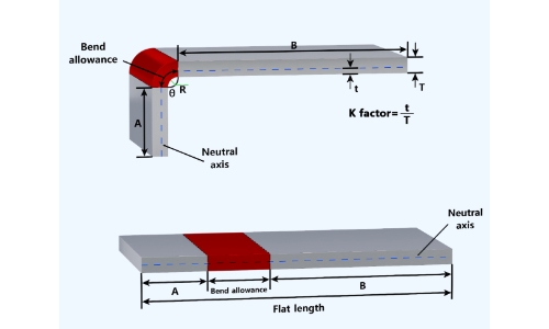
Neutral Axis
During bending, the outer surface stretches and the inner surface compresses. Between them is the neutral axis, which does not change length. It usually sits about one-third into the material from the inside surface. Knowing its position helps make accurate flat pattern layouts.
K-Factor
The K-Factor describes where the neutral axis lies within the material thickness. For 1 mm cold-rolled steel, it’s often around 0.33. For the same thickness of aluminum, it may be closer to 0.40. Using the right K-Factor ensures the flat blank bends to the correct final size.
Bend Allowance
Bending stretches the material, so designers must account for it. Bend allowance is the extra length added to ensure the flat sheet forms correctly. For example, a 1 mm steel sheet bent at 90° with a 1 mm radius typically needs about 1.6 mm of allowance. Including this in the flat pattern keeps the finished part within tolerance.
Cutting Basics
Cutting is the first step in most sheet metal projects. The quality of each cut affects how well the part bends, welds, or assembles later. Knowing common issues and simple rules helps make parts accurate and easy to produce.
Hole Diameter
Holes must be the right size and spacing to avoid damage during punching or laser cutting. A good rule is to keep the hole diameter at least equal to the sheet thickness. For example, a 2 mm steel sheet should have holes no smaller than 2 mm. Smaller holes can tear or distort the sheet, while properly sized holes give clean edges and longer tool life.
Distortion
Heat and stress from cutting can cause warping or bending, especially in thin sheets. Laser cutting may leave slight bowing on large panels under 1.5 mm thick. You can reduce distortion by spacing cuts farther apart, adding support tabs, or using waterjet cutting when flatness is critical.
Localized Hardening
Processes like laser or plasma cutting create high-heat zones along the edge. This can harden materials such as carbon steel. Hardened edges may crack during bending or wear down tools faster. Avoid problems by placing bends away from cut edges or adding a secondary process like edge grinding when needed.
Kerf
Kerf is the width of material removed by the cutting tool. Laser cutting usually ranges from 0.1 to 0.3 mm, depending on material thickness and power settings. Ignoring kerf can make holes undersized or slots too tight. Including kerf in the flat design ensures the final part matches the intended dimensions without rework.
Common Sheet Metal Design Mistakes to Avoid
Even experienced designers can overlook key manufacturing limits. Catching these common errors early improves part function and lowers production costs.
Overcomplicated Designs
Adding unnecessary features is a frequent mistake. Each extra bend, custom cutout, or special form increases tooling needs and production time. Complex designs require more machine setups, raise the risk of defects, and complicate assembly. Simplify by removing non-essential elements and combining parts into single, formed components when possible.
Poor Hole and Cutout Placement
Holes or cutouts too close to bends can deform during forming. Keep holes at least three times the material thickness away from bend lines. Avoid clustering holes in small areas, as this weakens the structure and can cause tearing. For electrical enclosures, space knockouts must be made carefully to maintain panel strength.
Overlooking Tolerances
Tight tolerances increase cost. Reserve ±0.005″ tolerances for critical mating features only. Use standard ±0.030″ tolerances for other dimensions. Clearly mark which dimensions are crucial and which tolerances can be relaxed. Remember that sheet metal naturally varies due to material memory and springback.
Wrong Material Selection
Choosing the wrong material can cause production issues or part failure. Avoid hardened steels for parts needing extensive bending. Aluminum offers corrosion resistance and lighter weight, but costs more than steel. For outdoor parts, use stainless steel or galvanized material. Check material availability and lead times when specifying unusual alloys.
Forgetting Assembly Considerations
Design parts with assembly in mind. Provide enough clearance for welding guns and rivet tools. Include alignment features like notches or tabs for easier positioning. Ensure hand access for assembly operations. Self-locating features can reduce the need for complex fixtures and speed up assembly.
Neglecting Finish Requirements
Finishes affect both design and function. Specify finish requirements early. Break sharp edges to help coatings stick. For powder coating, avoid areas where Faraday cage effects prevent paint from reaching corners. For plating, avoid designs that trap chemicals. Different finishes may need pretreatment, which can affect dimensions.
Get Started
Designing a part is just the first step. The real value comes when your sheet metal concept is made accurately and efficiently. By following simple design rules and choosing the right materials, you make fabrication easier and more predictable. Plan bends, holes, and features with real production in mind to reduce errors and waste.
Ready to turn your design into a high-quality sheet metal part? Contact us today for a fast quote and expert guidance on your project.