Modern sheet metal projects usually involve several teams — engineers, fabricators, suppliers, and clients. Problems start when their roles are not clearly defined. Even a well-organized project can fall apart if no one knows who is responsible for what. Many companies face this problem because they assume everyone understands “engineering responsibility” the same way, but that’s rarely the case.
In sheet metal fabrication, it’s essential to define responsibilities early. Engineers are responsible for design accuracy and setting correct tolerances. Fabricators focus on manufacturability, stable processes, and quality control. Suppliers handle material quality, certification, and traceability. Each role has a clear purpose, and mixing them often leads to confusion, wasted time, and extra cost.
Having clear ownership for every task helps prevent errors and blame. It also builds trust and improves communication between design and production teams, enabling the entire project to run more efficiently.
Defining Engineering Responsibility in Sheet Metal Projects
Clear responsibility is the foundation of a successful sheet metal project. When roles overlap or stay undefined, confusion spreads. Minor errors grow into significant delays.
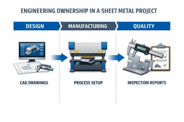
The Concept of Engineering Ownership
Engineering ownership means taking charge of every decision within your role and being accountable for the outcome. In the design stage, this means creating accurate drawings, realistic tolerances, and suitable material choices. Designers define how the part performs and how it fits into the assembly.
Manufacturing engineers handle how the design is made. They manage tooling, process flow, and quality checks. Their job is to meet specifications efficiently and consistently.
For example, if a designer calls for a 90° bend with tight tolerance, the fabricator must choose the proper setup and tooling to achieve that angle without distortion.
Why Boundaries Matter for Quality and Accountability?
Boundaries are not barriers — they are safeguards. They protect quality and accountability by allowing each team to focus on what they do best. When engineers know their exact responsibilities, fewer issues reach the production floor.
If the design team defines tolerances clearly, the fabricator can focus on maintaining them instead of interpreting them. When a dimension is missing or unrealistic, it gets flagged before production begins. This division reduces rework and shortens lead times.
Common Gray Areas Between Design and Manufacturing Teams
In real projects, not everything fits neatly into one team’s role. Gray areas often appear where design intent meets manufacturing limits.
For example, a designer may specify a sharp internal corner, but the fabricator knows a bend radius is needed to prevent cracking. Neither is wrong — they see the problem differently.
Tolerance control often causes the same issue. Designers want tight tolerances for assembly fit, while production prefers slightly wider ones for smoother fabrication. Without early discussion, this difference can lead to rejected parts or wasted time.
Design Stage Responsibilities
The design stage decides how successful a sheet metal project will be long before production starts. Engineers and fabricators need to work together early to align creative ideas with real production needs.
Product Designers’ Duties
Product designers create the blueprint for performance. Their main job is to produce precise 2D drawings and 3D models that fully describe the part — including dimensions, tolerances, materials, and surface finishes.
But design is more than just CAD work. Designers must consider how the part will be made — whether it can be bent, welded, or assembled using standard tools. For example, a sharp inside corner may crack during bending, but adding a small radius can prevent that without changing the function.
Designers should also follow standard practices. Hole sizes should match available punch tools, bend allowances should match sheet thickness, and materials should suit the product’s working environment. These small details save time, reduce cost, and prevent trial-and-error later.
Fabricator Input During DFM
Design for Manufacturability (DFM) is where design ideas meet production reality. It’s the stage where the fabricator’s experience adds real value.
Fabricators review the design to check if it can be produced efficiently and consistently. They look for problem areas — holes too close to bends, very tight tolerances, unnecessary cutouts, or surfaces that are hard to finish. For instance, moving a hole just 2 mm away from a bend line can prevent cracking and simplify the tooling setup.
Their feedback isn’t about changing the design’s intent — it’s about improving how that design can be built. The goal is not to challenge the engineer but to make the part easier, faster, and more reliable to produce.
A strong DFM process depends on open teamwork:
- Designers explain the purpose and function of each feature.
- Fabricators provide real production data, tool limits, and setup advice.
When both sides collaborate early, parts move through production smoothly. Costs go down, lead times shorten, and both teams succeed — the designer for accuracy and the fabricator for efficiency.

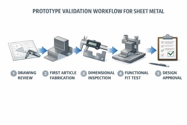
Prototyping and Pre-Production Roles
Before full production begins, the prototype stage connects design ideas with real-world manufacturing. It checks whether the drawings, materials, and processes work together as planned.
Collaborative Review of Drawings and 3D Models
Once the design is ready, engineers and fabricators should review it together — either in person or online. This joint review helps both sides confirm that the design intent matches what can actually be made.
Designers focus on geometry, fit, and how parts assemble. Fabricators check bend lines, hole spacing, and tolerances to ensure the part can be made using existing machines and standard tools.
For example, a designer may want a seamless corner, but the fabricator might suggest a different welding method to avoid distortion. Talking about these details early prevents costly changes later.
Dimensional Validation and Functional Testing
After the prototype is built, testing confirms whether the design performs as expected. Engineers measure key features using tools such as calipers, gauges, or CMMs to ensure all dimensions meet the drawing’s tolerances.
Next comes functional testing — checking how the part works in real use. Does it assemble smoothly, fit with other components, and handle its intended load? For example, a bracket may meet all dimensions but still bend under weight.
If problems appear, the focus should be on finding the cause — whether it’s a design issue, tooling setup, or process variation. Fixing it now prevents bigger problems once mass production begins.
Documentation Handoff — What Data the Manufacturer Should Receive
Before production starts, all approved data must be handed off cleanly. The manufacturer should receive a complete digital package that includes:
- 2D drawings and 3D CAD files (clearly labeled with revisions)
- Material and surface finish specifications
- Critical tolerances and inspection points
- Assembly or welding instructions, if needed
Every file should have version control to avoid confusion about which version of the drawing is current.
Missing or unclear documentation is a significant cause of rework in fabrication. A transparent handoff ensures the factory builds exactly what was approved — with no outdated files, no misunderstandings, and no delays.
Production Engineering Boundaries
Once a project enters production, control shifts from design planning to real manufacturing. At this stage, clarity is everything — who manages the process plan, and who approves design changes?
Fabricator’s Responsibility for Process Planning
The fabricator is responsible for how the part is made. Their team defines every step — cutting, bending, welding, finishing, and inspection. They select the proper tooling, set machine parameters, and write work instructions to ensure consistent quality.
All planning must follow the approved design, not assumptions.
For example, if a drawing calls for a 90° bend with ±0.5° tolerance, the fabricator decides which press brake, tooling, and setup can achieve that accuracy repeatedly.
If a feature can’t be produced as designed — such as a bend that’s too tight or a weld that’s hard to reach — the fabricator must report it immediately. They are responsible for identifying the problem, but not allowed to change the design without approval.
Client or Designer’s Responsibility for Design Change Approvals
Even during production, the client or design engineer keeps full ownership of the design. Any change that affects geometry, function, or appearance must be reviewed and approved by them.
If the fabricator suggests a more efficient method — such as replacing two welded flanges with one bent part — the proposal must be returned to the design owner. Only they can confirm that the modification won’t affect fit, strength, or appearance.
Every approved change should be recorded with a new drawing revision, updated CAD file, and dated approval note. This maintains full traceability and avoids confusion.
Unapproved “on-the-fly” changes often cause bigger problems later, such as misaligned assemblies or rejected parts. A straightforward approval process keeps production accurate, consistent, and accountable.
Quality and Inspection Responsibilities
Quality control is where engineering plans turn into measurable results. No matter how strong the design or process plan is, a project’s success depends on consistent inspection, clear documentation, and defined accountability.
Setting Inspection Standards and Who Defines Them
Inspection starts long before production. The design engineer decides what needs to be inspected — dimensions, tolerances, surface finishes, and key functional features. These details must be listed clearly in the drawings and specifications.
The fabricator determines how to inspect them. They choose the right measuring tools — calipers, gauges, CMMs, or optical scanners — and set inspection frequency.
For example, a hole with a ±0.1 mm tolerance may need to be checked on every batch, while cosmetic surfaces can be inspected by sampling.
Traceability and Documentation
Traceability connects every finished part to its source — the material, the process, and the operator. The fabricator manages this record to keep production transparent and reliable.
Typical traceability records include:
- Material certificates and batch numbers
- Inspection reports and process logs
- Operator or machine IDs for each batch
- Calibration records for all measuring equipment
Each part should carry a unique identifier — such as a batch code, QR label, or stamped serial number — linking it to its full inspection history.
When a problem occurs, traceability enables engineers to identify the root cause quickly. It answers whether the issue came from material, tooling, or setup changes.
Logistics and Supply Chain Responsibilities
Once the product leaves the factory, engineering responsibility doesn’t end — it simply shifts. Quality can still be lost during sourcing, packaging, or transport if duties are unclear.
Who Manages Supplier Qualification and Material Sourcing?
Material quality begins with supplier control. The manufacturer usually manages supplier qualification because they work directly with material vendors and understand production needs. They verify supplier certifications, review test reports, and check compliance with standards such as ASTM, ISO, or RoHS.
The design engineer defines the material’s requirements — its grade, finish, and mechanical strength. The manufacturer ensures that suppliers consistently meet those requirements.
For example, if a project requires stainless steel 304 with a #4 brushed finish, the engineer specifies that standard, and the fabricator confirms the supplier provides the correct sheet with full traceability.
Responsibility for Packaging Design and Shipment Protection
Packaging is a key part of product quality. The manufacturer is responsible for designing packaging that protects parts during handling and transport. They know the product’s shape, surface sensitivity, and stacking method, which determines how each piece should be wrapped, cushioned, and boxed.
The client or designer reviews and approves packaging standards before shipment. They confirm requirements like weight limits, corrosion protection, and labeling details.
For example, polished aluminum panels may need film protection and foam inserts, while powder-coated parts might require partitioned boxes to avoid scratches.
Best Practices for Setting Responsibility Boundaries
Transparent processes, organized communication, and the right tools keep every project running smoothly. These best practices help teams avoid overlap, reduce mistakes, and maintain accountability from concept to delivery.
Use of RACI Matrices (Responsible, Accountable, Consulted, Informed)
A RACI matrix is a simple but effective tool for defining responsibilities. It shows who is Responsible (does the task), Accountable (approves the result), Consulted (gives input), and Informed (receives updates).
In sheet metal projects, this helps clarify the roles of engineering and production.
For example, during the DFM stage:
- The designer is Responsible for updating drawings.
- The project manager is Accountable for final approval.
- The fabricator is consulted for production feedback.
- The quality team is informed about inspection changes.
Clear Communication and Documentation Protocols
Written communication keeps information accurate. Every change — from design updates to tolerance adjustments — should be recorded and easily traceable. Ideally, all updates are stored in a shared system that everyone can access.
Teams should agree on:
- Where files are stored and who can update them.
- How change requests and approvals are submitted.
- Which version of each drawing is the latest?
Regular Engineering Review Meetings
Scheduled review meetings help maintain clear boundaries. They give teams a chance to confirm progress, resolve questions, and adjust roles if needed.
Typical checkpoints include:
- Pre-production review – confirm manufacturability and tooling plans.
- Mid-run review – check production stability and discuss improvements.
- Post-project review – capture lessons learned for future projects.
Conclusion
Clear engineering boundaries do more than improve efficiency — they prevent rework, reduce delays, and keep teams focused on what truly matters: delivering reliable, cost-effective, and high-quality sheet metal parts. When every engineer, fabricator, and client understands their scope, collaboration becomes smoother, and problems get solved early.
Ready to Make Your Next Project Smoother?
If your next fabrication project involves multiple stages or complex coordination, start with clarity. Contact us today to discuss design reviews, manufacturability feedback, or process optimization — and turn your next build into a data-driven success.
FAQs
What Happens if Design Errors Are Found During Production?
If a design flaw appears during production, the fabricator should stop work and notify the design engineer. The engineer reviews the issue, updates the drawing, and issues a new revision. Production resumes only after written approval, keeping every change traceable.
Who Revises Tolerances After DFM Feedback?
The design engineer has full authority over tolerances. Fabricators may suggest adjustments during DFM, but only engineers can modify official drawings. This keeps functional intent intact while allowing efficient manufacturing.
How Should Disputes Over Part Quality Be Resolved?
Quality disputes should be based on data, not opinions. Both teams should review inspection reports, drawings, and reference standards together. If no agreement is reached, a third-party inspection or recognized standard, such as ISO or ASTM, provides an objective conclusion.
When Should Clients Involve Fabricators in the Design Phase?
Fabricators should be involved before the final design approval. Early collaboration during prototyping or DFM helps identify potential issues, reduces lead time, and avoids costly revisions later.
How Can Small Manufacturers Define Responsibilities Clearly?
Start with a simple responsibility checklist or RACI chart. Define who approves designs, who plans the processes, and who handles inspection. Even small teams benefit from this structure — it builds consistency, accountability, and trust throughout every project.
Hey, I'm Kevin Lee

For the past 10 years, I’ve been immersed in various forms of sheet metal fabrication, sharing cool insights here from my experiences across diverse workshops.
Get in touch
Kevin Lee
I have over ten years of professional experience in sheet metal fabrication, specializing in laser cutting, bending, welding, and surface treatment techniques. As the Technical Director at Shengen, I am committed to solving complex manufacturing challenges and driving innovation and quality in each project.
Related Resource