Eine Abweichung von einem Grad in einer Blechbiegung mag winzig klingen, aber in der Montage kann das bedeuten, dass sich eine Tür nicht mehr schließen lässt oder ein Loch in einer Halterung nicht mehr in einer Linie liegt. Studien aus Fertigungswerkstätten zeigen, dass mehr als 60% der Nacharbeiten bei Blechbaugruppen auf ungenaue Biegungen oder schlecht definierte Toleranzen zurückzuführen sind.
Die Biegetoleranz definiert die zulässige Abweichung zwischen Entwurf und Produktion. Sie verbindet die ideale CAD-Zeichnung mit den physikalischen Grenzen von realen Materialien, Werkzeugen und Bedienern. Perfekte Genauigkeit ist unmöglich - bei jeder Biegung wird das Metall gedehnt, gestaucht und leicht verändert. Das Ziel ist kontrollierte Konsistenz, nicht Perfektion.
In diesem technischen Leitfaden erfahren Sie, wie Toleranzen funktionieren, was sie beeinflusst und wie Sie Blechteile konstruieren, die passen, funktionieren und effizient gefertigt werden.
Verständnis der Toleranzen beim Blechbiegen
Eine Biegetoleranz gibt an, wie viel Abweichung bei einem Biegewinkel oder einer Flanschlänge nach dem Umformen zulässig ist. Zum Beispiel kann ein 90°-Design nach dem Umformen 89° oder 91° ergeben. Dieser Unterschied von ±1° ist der Toleranzbereich.
Gut definierte Toleranzen verhindern kostspielige Abweichungen zwischen Teilen. Außerdem ermöglichen sie es den Ingenieuren, die erreichbare Qualität vorherzusagen, bevor die Produktion beginnt. Ohne sie könnten zwei Anbieter identische Zeichnungen anfertigen und dennoch Baugruppen liefern, die nicht übereinstimmen.
In Präzisionsindustrien wie medizinischen Geräten, EV-Batteriegehäusen und industrieller Automatisierung sorgen konstante Toleranzen für eine reibungslose Montage und langfristige Zuverlässigkeit.
Gängige Arten von Biegetoleranzen
| Typ | Beschreibung | Typischer Bereich | Anmeldung |
|---|---|---|---|
| Eckig | Zulässige Abweichung des Biegewinkels | ±1° - ±2° | Definiert die Teilegeometrie |
| Linear (Flansch) | Variation des Abstands von der Biegelinie zum Rand | ±0,25 mm (±0,010 Zoll) | Passform und Ausrichtung der Steuerelemente |
| Kumulativ | Gesamtfehler über mehrere Biegungen | ±0,5 - ±1,0 mm insgesamt | Beeinflusst die Gehäusemontage |
Jede Biegung bringt zusätzliche Abweichungen mit sich, und bei Gehäusen oder Chassis mit mehreren Biegungen wird der Toleranzausgleich kritisch. Fünf Biegungen mit jeweils ±0,25 mm könnten beispielsweise eine Verschiebung von 1,25 mm am letzten Flansch verursachen - genug, um die Befestigungslöcher falsch auszurichten.
Tipp des Ingenieurs: Definieren Sie Gesamtabmessungen als "kontrollierte" Merkmale und notieren Sie sekundäre Biegungen als "nur Referenz", um unnötige Stapel zu vermeiden.
Warum engere Toleranzen nicht immer besser sind?
Es ist verlockend, den kleinstmöglichen Bereich festzulegen, weil man glaubt, dass dies Qualität garantiert. In Wirklichkeit erhöhen zu enge Toleranzen die Kosten, verlangsamen die Produktion und erhöhen die Ausschussrate. Das Erreichen von ±0,1 mm anstelle von ±0,25 mm kann spezielle Werkzeuge, langsamere Umformgeschwindigkeiten und 100 %-Prüfungen erfordern.
Studien über die Herstellungskosten haben ergeben, dass eine Halbierung der Toleranzbreite die Produktionskosten um 30-50% erhöhen kann. Anstatt eine Nullabweichung anzustreben, sollten Sie funktionsbezogene Toleranzen anstreben - eng, wo es kritisch ist, locker, wo nicht.
Beispiel:
- PCB-Montageflansch → ±0,15 mm (kritische Passung)
- Äußerer Rand der Abdeckung → ±0,5 mm (nur ästhetisch)
Schlüsselfaktoren, die die Biegetoleranzen beeinflussen
Die Biegegenauigkeit hängt von vielen Variablen außerhalb der Zeichnung ab. Hier wird untersucht, wie Materialverhalten, Werkzeugpräzision und Prozesssteuerung die erzielbaren Ergebnisse bestimmen.
Materialeigenschaften
Die Materialzusammensetzung und der Härtegrad bestimmen weitgehend, wie genau sich ein Blech biegen lässt.
- Aluminium 5052-H32 zeigt etwa 2-3° Rückfederung.
- Baustahl (CRS) durchschnittlich 1°-1,5°.
- Edelstahl 304 kann um 3°-5° ausschlagen, insbesondere bei kleinen Radien.
Rückfederung wächst mit der Zugfestigkeit. Biegen Sie quer zur Faser, um konsistente Ergebnisse zu erzielen; Biegen parallel zur Faser erhöht das Risiko von Rissen und Winkelabweichungen um bis zu 40%.
Design-Tipp: Wenn Ihr Projekt mehrere Materialien umfasst, erstellen Sie frühzeitig eine Testbiegematrix, um die Basis-K-Faktoren für jeden Plattentyp festzulegen.
Dicke und Biegeradius
Je dicker das Material ist, desto schwieriger ist es, die Verformung zu kontrollieren. Ein kleiner Innenradius (< 1× Dicke) konzentriert die Spannung und macht den Winkel weniger vorhersehbar. Bei 1T (Radius = Dicke) liefern die meisten Metalle zuverlässige Ergebnisse; bei ≥ 2T sinkt das Rissrisiko, aber die Variation der Flanschlänge nimmt zu.
Empirischer Leitfaden:
Jede Zunahme der Dicke um 0,5 mm kann den endgültigen Biegewinkel um ≈ 0,2° verändern, wenn Werkzeug und Druck konstant bleiben. Ein frühzeitiger Abgleich des Radius-Dicken-Verhältnisses im CAD vermeidet spätere Korrekturen an der Abkantpresse.
Werkzeugbau und Abkantpressen Präzision
Die Werkzeugqualität definiert die erreichbare Toleranzgrenze. Moderne servoelektrische CNC-Abkantpressen erreichen eine Winkelwiederholgenauigkeit von ±0,5°; ältere mechanische Abkantpressen schwanken um ±2° oder mehr.
Wichtige Einflüsse:
- Matrizenbreite und Stempelwinkel: Zu schmal = Überbiegung; zu breit = Unterbiegung.
- Werkzeugverschleiß: Erhöht die zeitliche Abweichung um ±0,25 mm.
- Kalibrierung der Maschine: Eine Abweichung von > 0,1 mm kann den Winkel um 1° verändern.
DFM-Einblick: Erkundigen Sie sich bei der Beschaffung von Teilen bei den Lieferanten nach dem Bremstyp und dem Kalibrierungsplan. Erwarten Sie von servogesteuerten Systemen eine geringere Wiederholgenauigkeit.
Bedienerfähigkeiten und Einstellungsvariablen
Selbst bei der Automatisierung beeinflusst der Mensch das Ergebnis. Erfahrene Bediener kompensieren Dickenunterschiede von Los zu Los, Schmiermittel und Temperaturschwankungen. Unsachgemäßes Einspannen oder ungleichmäßiger Druck führen zu ungleichmäßigen Winkeln entlang der Biegelänge.
Eine konsequente Ausrichtung des Hinteranschlags und Probebiegungen vor dem vollen Durchlauf helfen, die Maßstabilität zu erhalten. Bei kritischen Teilen sollten Sie die anfänglichen Testdaten aufzeichnen, um die Maschinenabweichungen in zukünftigen Chargen anzupassen.
Wie man praktische Toleranzen festlegt?
Das richtige Gleichgewicht der Toleranzen gewährleistet Herstellbarkeit und Funktion. Die folgenden Erkenntnisse zeigen, wie man erreichbare Grenzen definiert und sie effektiv mit den Herstellern kommuniziert.
Gleichgewicht zwischen Design und Herstellbarkeit
Angemessene Toleranzen gewährleisten die Funktion der Teile, ohne die Kosten in die Höhe zu treiben. Zu enge Grenzen erhöhen den Werkzeugverschleiß, die Prüfzeit und die Ausschussquote. Lockere Toleranzen riskieren schlechte Passform und Vibrationsprobleme.
Praktische Reichweiten nach Anwendung:
- Unterhaltungselektronikplatten → ±0,25 mm / ±1°.
- Kfz-Halterungen → ±0,5 mm / ±2°.
- Schwere Maschinenrahmen → ±1,0 mm / ±3°.
Beispiel für Kostenauswirkungen:
Die Verringerung einer Flanschtoleranz von ±0,5 mm auf ±0,25 mm erhöht die Herstellungskosten in der Regel um 30-40 %.
Definieren Sie zuerst die funktionskritischen Dimensionen (CTF) und lockern Sie den Rest.
Verweis auf Industrienormen
Verwenden Sie ISO 2768 oder DIN 6935 als gemeinsame Sprache zwischen Konstrukteur und Verarbeiter.
| Toleranzklasse | Linear (≤30 mm) | Winkel (°) | Anwendungsfall |
|---|---|---|---|
| Geldstrafe (f) | ±0,1 mm | ±0.5 | Präzisionsbaugruppen |
| Mittel (m) | ±0,2 mm | ±1 | Allgemeine Blechbearbeitung |
| Grob (c) | ±0,5 mm | ±1.5 | Große Strukturen |
Die Angabe von Toleranzen nach Norm verhindert Streitigkeiten und klärt die Erwartungen der internationalen Lieferanten.
Typische erreichbare Reichweiten in modernen Geschäften
| Eigenschaften | Typische Toleranz | Anmerkungen |
|---|---|---|
| Biegewinkel | ±1° | CNC-Abkantpresse |
| Länge des Flansches | ±0,25 mm | ≤ 1,5 mm dickes Blech |
| Mehrfach gebogene Dimension | ±0,5 mm | Kumulierter Fehler |
| Abstand zwischen Bohrung und Biegung | ±0,25 mm | Kritische Ausrichtung |
| Gesamtgröße | ±0,75 mm | Nach der Bildung |
Nehmen Sie diese Bereiche in Zeichnungen oder technische Vereinbarungen auf, um erreichbare Qualitätsziele festzulegen.
Effektive Kommunikation von Toleranzen
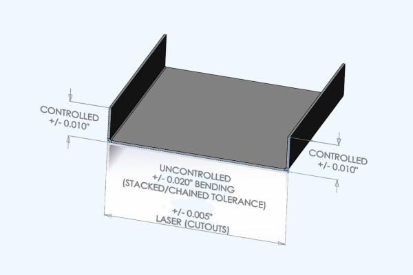
Markieren Sie kritische Maße deutlich auf Zeichnungen - Farbcodes oder Merkmalskennzeichnungen helfen dem Bediener, sich auf die wichtigsten Punkte zu konzentrieren. Geben Sie Hinweise wie "Unkontrollierte Maße ±0,5 mm, sofern nicht anders angegeben". Auf diese Weise wird verhindert, dass Zeit mit dem Überprüfen unbedeutender Merkmale verschwendet wird.
Konstruktionsüberlegungen für genaues Biegen
Eine gute Konstruktion minimiert Abweichungen, bevor die Produktion überhaupt beginnt. In diesem Abschnitt werden die Geometrie, die Faserrichtung und die Berechnungen beschrieben, die zu gleichmäßigen, wiederholbaren Biegungen führen.
Vermeiden von Übertoleranz
Die Vorgabe extrem enger Toleranzen verbessert nicht immer die Qualität, sondern erhöht oft die Kosten und Verzögerungen. Jeder zusätzliche 0,1 mm an Präzision kann spezielle Werkzeuge, eine langsamere Umformgeschwindigkeit und zusätzliche Prüfschritte erfordern. Mit der Zeit führt dies zu einem geringeren Durchsatz und höheren Ausschussraten.
Eine funktionsbasierte Toleranzstrategie hilft, Genauigkeit und Kosten in Einklang zu bringen.
- Kritische Dimensionen: Abstände zwischen Bohrung und Biegung, Gegenflansche, Dichtungsflächen → enge Kontrolle (±0,15-0,25 mm).
- Unkritische Dimensionen: Dekorplatten, Stützlaschen → entspannter Bereich (±0,5-1 mm).
Anmerkung des Ingenieurs: Bei einem Projekt für ein Telekommunikationsgehäuse konnte durch die Verringerung der Seitenflanschtoleranzen von ±0,2 mm auf ±0,5 mm die Einrichtungszeit um 20% reduziert werden, ohne dass die Passgenauigkeit oder Steifigkeit beeinträchtigt wurde.
Berücksichtigung der Rückfederung
Rückfederung tritt auf, wenn das Metall nach dem Biegen teilweise in seine ursprüngliche Form zurückkehrt. Der Biegewinkel "öffnet sich", insbesondere bei härteren Materialien. Typische Rückfederungswerte:
| Werkstoff | Typische Rückfederung | Anmerkungen |
|---|---|---|
| Aluminium 5052-H32 | 2°-3° | Hohe Elastizität |
| Edelstahl 304 | 3°-5° | Stärker ausgeprägt |
| Baustahl (CRS) | 1°-1.5° | Leichter zu kontrollieren |
Kompensationsmethoden:
- Überbiegen: Biegen Sie leicht über den Zielwinkel hinaus (z. B. 88° Ziel → Form zu 87°).
- Bodenbildung oder Prägung: Hochdruckumformung, die die Biegezone plastisch verformt und die Rückfederung minimiert.
- Adaptive CNC-Steuerung: Echtzeit-Lasersensoren zur automatischen Anpassung der Rammtiefe.
Moderne servoelektrische Abkantpressen können durch Live-Rückfederungsmessung eine Konsistenz von ±0,5° erreichen, selbst bei gemischten Materialchargen.
Faserrichtung und Biegeachse
Die Walzrichtung des Metalls wirkt sich direkt auf die Rissfestigkeit und Wiederholbarkeit aus.
- Biegen quer zur Faser: Gleichmäßigere Dehnung, weniger Rissbildung.
- Biegen parallel zur Faser: Erhöht das Risiko von Brüchen und Rückfederungsschwankungen.
Bei dünnen nichtrostenden oder hochfesten Legierungen zeichnen Risse entlang der Biegelinie oft den Faserverlauf nach. Um dies zu vermeiden, geben Sie auf den Zeichnungen immer die Biegerichtung an - z. B., "Biegelinie rechtwinklig zur Rollrichtung".
Einblick in die Gestaltung: Bei einem rostfreien 304er-Blech (1,5 mm dick) konnte durch die Umstellung der Biegeausrichtung senkrecht zur Maserung die Winkelabweichung in den Tests von ±2,5° auf ±1° reduziert werden.
Kontrolle von Kurvenabzug und -zulage
Der Biegeabzug (BD) und die Biegung Zulage (BA) Berechnungen definieren, wie viel Material im Biegebereich verwendet wird - falsche Werte führen direkt zu Flanschlängenfehlern.
Wichtige Formeln:
- BA = (π/180) × Biegewinkel × (R + K × T)
- BD = 2 × Flanschlänge - Flachlänge
Wo:
- R = innerer Biegeradius
- T = Materialstärke
- K = K-Faktor (Verhältnis zwischen der Lage der neutralen Achse und der Dicke, typischerweise 0,3-0,5)
Beispiel:
Für eine 90°-Biegung, R = 1,5 mm, T = 1,0 mm, K = 0,4 →
BA = (π/180 × 90) × (1,5 + 0,4 × 1,0) ≈ 1,67 mm
Durch die Verwendung der korrekten BA wird sichergestellt, dass die Länge des flachen Musters mit den endgültigen Abmessungen übereinstimmt, wodurch Nacharbeit und Ausschuss reduziert werden.
Verwendung von DFM-Feedback im frühen Entwurf
Fordern Sie vor der Fertigstellung der Teilezeichnungen eine Überprüfung der Biegefähigkeit von Ihrem Lieferanten an. Die Hersteller können reale Daten zur Verfügung stellen, z. B. erreichbare Winkel, bevorzugte Radien und Werkzeugbreitenoptionen. Durch diese Zusammenarbeit werden unrealistische Toleranzannahmen vermieden, die die Angebotserstellung verzögern und die Werkzeugkosten erhöhen.
Kurzer Tipp: Beziehen Sie bei Präzisionsgehäusen Ihren Lieferanten beim Biegen von Prototypen mit ein - verwenden Sie Probestücke zur Feinabstimmung von BD und Rückfederungskorrektur vor der Massenproduktion.
Fortgeschrittene und oft übersehene Aspekte
Modernes Biegen umfasst mehr als nur Winkel und Abmessungen. Erfahren Sie, wie GD&T, Automatisierung und Echtzeit-Steuerungstechnologien die Genauigkeit und Prozesssicherheit erhöhen.
Geometrische Bemaßung und Tolerierung (GD&T) bei Biegeteilen
Traditionelle ±-Toleranzen konzentrieren sich auf einzelne Maße, beschreiben aber nicht wie Merkmale in 3D ausrichten. GD&T definiert funktionale Beziehungen wie Ebenheit, Rechtwinkligkeit und Position.
Beispiel:
Eine Halterung kann die Biegetoleranz von ±1° einhalten, aber nicht montiert werden, weil ihre Flansche nicht rechtwinklig sind. Durch die Anwendung von GD&T-Symbolen - z. B. Rechtwinkligkeit von 0,2 mm zum Nullpunkt A - kontrollieren Ingenieure die tatsächliche funktionale Ausrichtung.
GD&T gewährleistet Form-, Passform- und Funktionskonsistenz über einfache lineare oder winklige Grenzen hinaus.
Automatisierung und Echtzeit-Kompensation
Industrie 4.0-Abkantpressen verwenden jetzt eine geschlossene Winkelsteuerung, Laserscanner und intelligente Bombiersysteme. Diese Systeme messen jede Biegung, während sie stattfindet, und vergleichen das Echtzeit-Feedback mit dem programmierten Winkel. Die Maschine passt dann den Stößeldruck sofort an und gleicht Dicken- oder Härteunterschiede aus.
Die Forschung veröffentlicht in der Zeitschrift für Fertigungssysteme (2022) stellte fest, dass die automatische Winkelkorrektur Biegefehler um 35% und Ausschuss um 28% reduzierte. Diese Technologie vereinfacht auch die Bedienerschulung und verringert die Abhängigkeit von manuellen Entscheidungen.
Allgemeine Probleme und Fehlerbehebung
Selbst sorgfältig konfigurierte Konfigurationen können unter realen Bedingungen versagen. Diese praktischen Tipps helfen bei der Diagnose und schnellen Behebung häufiger Biegetoleranzprobleme.
| Problem | Wahrscheinliche Ursache | Empfohlene Lösung |
|---|---|---|
| Ungleiche Biegewinkel | Werkzeugverschleiß oder ungleichmäßiger Druck | Werkzeuge nachschleifen, Abkantpresse neu kalibrieren |
| Flanschverschiebung | Hinteranschlagversatz oder Spannfehler | Kalibrierung und Parallelität des Messgeräts prüfen |
| Lochverzerrung in der Nähe der Biegung | Bohrung zu nahe an der Biegelinie | Halten Sie ≥ 2× Materialstärke von der Biegung |
| Schlechte Passgenauigkeit bei der Montage | Kumulierter Multibiegungsfehler | Überprüfung von Reihenfolge und Reihenfolge der Biegungen |
| Übermäßige Rückfederung | Material mit hoher Streckgrenze | Leicht überbiegen oder Prägemethode anwenden |
Tipp: Dokumentieren Sie wiederkehrende Toleranzabweichungen. Mit der Zeit werden Ihre historischen Daten zu einem Prognosemodell für das Material- und Maschinenverhalten.
Schlussfolgerung
Bei der Kontrolle von Blechbiegetoleranzen geht es nicht darum, perfekte Zahlen zu erzielen, sondern vorhersehbare Ergebnisse zu entwickeln. Durch die Abstimmung der Konstruktionsabsicht mit den Fertigungsmöglichkeiten können die Teams den Ausschuss reduzieren, die Vorlaufzeiten verkürzen und die Präzision bei jeder Produktionscharge aufrechterhalten.
Bei Shengen kombiniert unser Ingenieurteam Präzisionswerkzeuge, automatisierte Abkantpressen und ISO 9001-zertifizierte Qualitätssysteme, um Blechteile mit engen Toleranzen zu liefern - vom Prototyp bis zur Großserienfertigung. Laden Sie Ihre CAD-Dateien noch heute hoch für eine kostenlose DFM-Überprüfung und einen Bericht zur Toleranzoptimierung innerhalb von 24 Stunden.
FAQs
Was ist eine realistische Biegetoleranz für Teile aus rostfreiem Stahl?
Bei rostfreiem Stahl mit einer Dicke von weniger als 2 mm sind in der Regel ±1° im Winkel und ±0,25 mm in der Flanschlänge erreichbar.
Wie kann ich die Rückfederung reduzieren?
Erhöhen Sie den Biegeradius, biegen Sie leicht über, oder verwenden Sie eine Sohlenbildung mit höherem Umformdruck.
Warum weisen mehrfach gebogene Teile größere Abweichungen auf?
Jede Biegung führt zu kleinen Fehlern, die sich summieren. Überprüfen Sie die Biegefolge und verwenden Sie vorrichtungsbasiertes Formen, um Konsistenz zu gewährleisten.
Welche Normen gelten für Biegetoleranzen?
ISO 2768-1/2 und DIN 6935 definieren allgemeine Längen- und Winkeltoleranzen für gefertigte Teile.
Hey, ich bin Kevin Lee

In den letzten 10 Jahren bin ich in verschiedene Formen der Blechbearbeitung eingetaucht und teile hier coole Erkenntnisse aus meinen Erfahrungen in verschiedenen Werkstätten.
Kontakt aufnehmen
Kevin Lee
Ich verfüge über mehr als zehn Jahre Berufserfahrung in der Blechverarbeitung und bin auf Laserschneiden, Biegen, Schweißen und Oberflächenbehandlungstechniken spezialisiert. Als Technischer Direktor bei Shengen bin ich bestrebt, komplexe Fertigungsherausforderungen zu lösen und Innovation und Qualität in jedem Projekt voranzutreiben.
Verwandte Ressource

Elektrolytisch verzinkter Stahl: Leitfaden zur Verarbeitung und Auswahl

Stanzen vs. Laserschneiden: Kosten, Geschwindigkeit und DFM-Zwischenziele

Kehlnaht-Bearbeitung: Was die Kosten und die Qualität der Teile bestimmt
