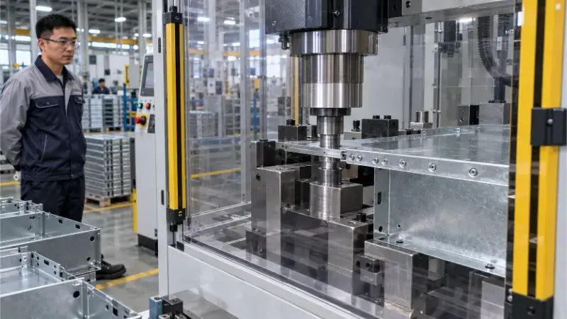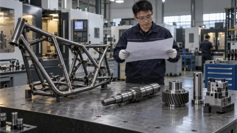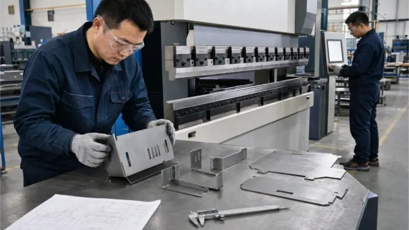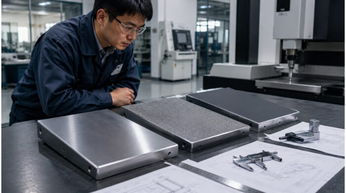
Press joining, commonly known as clinching, is a cold-forming process that connects two or more layers of sheet metal without welding or separate fasteners. It utilizes a punch and die to plastically deform the sheets, creating a permanent mechanical interlock.
However, the term “press joining” causes frequent confusion in manufacturing RFQs—buyers and engineers often mistakenly use it when referring to threaded hardware insertion (PEM fasteners) or hydraulic pipe fittings.
This guide cuts through the terminology to focus strictly on fastener-free sheet metal clinching. Whether you are designing a high-volume HVAC enclosure or evaluating assembly costs, this article breaks down how the process works, the exact DFM clearances required, which metal alloys to avoid, and when this cold-fastening method actually lowers your total production cost.
Key Takeaways
- Sheet metal press joining usually refers to clinching.
- The process uses local deformation instead of heat or separate fasteners, making it ideal for pre-coated metals but unsuitable for brittle alloys.
- Material formability and two-sided tool access are essential.
- Joint performance depends strictly on the formed geometry and load direction.
- Production speed alone does not determine the total assembly cost.

How Press Joining Works in Sheet Metal?
Understanding the core mechanics of press joining is crucial for avoiding costly engineering mistakes. Let’s break down how this process creates secure connections without using any external fasteners.
Clinching Without Separate Fasteners
Clinching joins two or more layers of sheet metal using a specialized punch and die set. The tooling forces the overlapping sheets to undergo local plastic deformation, locking them together. Because the connection relies entirely on the flow of the parent material, a clinched joint requires:
- No rivets
- No screws
- No welding wire or gas
- No adhesives
- No pre-drilled connecting holes
Related Press Joining Processes
Confusion often arises during RFQ discussions because “press joining” means different things across manufacturing sectors. The table below outlines the primary differences to ensure accurate engineering communication:
| Process | Typical Parts | Joining Principle |
|---|---|---|
| Clinch joining | Overlapping sheet metal | Formed mechanical interlock |
| Interference press fit | Shaft and hole | Dimensional interference |
| Pipe press fitting | Pipe and fitting | Crimping and sealing ring |
| Hardware insertion | Nuts, studs, and standoffs | Sheet material flows into a fastener undercut |
Shop Note: We frequently see RFQs asking for “press joining” when the drawing actually requires threaded hardware insertion (such as PEM standoffs). If your design requires threaded inserts, refer to our Hardware Insertion Guide. The rest of this article focuses exclusively on fastener-free sheet metal clinching.
Which Materials Work Best for Clinch Joining
Not all sheet metals can survive the intense deformation required for clinching. Discover how material flow dictates joint strength and which specific alloys perform best on the shop floor.
Controlled Material Flow
Creating a clinch joint follows a strict mechanical sequence. The sheets overlap over a die, and a blank holder clamps them to prevent wrinkling. The descending punch pushes the material downward. As the punch hits the bottom of its stroke, the bottom layer of material expands outward into the die cavity, enveloping the top layer.
This process requires excellent material ductility. If the sheet metal lacks flow characteristics, it will fracture instead of expanding. As a rule of thumb, alloys with an elongation below 10% (such as 6061-T6 aluminum) are prone to cracking during clinching. In contrast, highly formable materials like 5052 aluminum, SPCC, or low-carbon steel yield excellent, consistent interlocks.
Interlock and Neck Thickness
The mechanical strength of a clinched joint does not rely primarily on cold working; it depends heavily on three cross-sectional dimensions formed during the press stroke:
- Interlock (Undercut): The radial distance the top sheet penetrates under the bottom sheet. A larger interlock directly increases the joint’s pull-out strength.
- Neck Thickness: The thinnest section of the top sheet material along the wall of the joint. This dimension heavily influences shear strength and fracture resistance.
- Bottom Thickness: The remaining thickness at the base of the button, which reflects the press depth and indicates proper material flow.
Tooling and Press Force
Stable production requires matching the tooling parameters to the specific sheet metal stack. The final joint geometry shifts based on:
- Punch profile and die depth
- Tooling clearance
- Press force and stroke length
- Total sheet stack thickness
Applying insufficient press force creates a small interlock, risking joint separation under load. Excessive force causes severe neck thinning, bottom cracking, and visible surface damage.
In modern sheet metal production, relying solely on visual checks for these variables is risky. Quality is maintained by monitoring the force-displacement curve on the press machine for every single stroke. This allows the shop to instantly detect anomalies like tool wear, missing layers, or incorrect sheet thickness before parts move to the next assembly stage.
How to Design Parts for Reliable Clinching?
A strong clinch joint starts long before the metal ever hits the press. Following these core DFM rules ensures your sheet metal parts assemble cleanly and hold securely.
Material and Sheet Stack
Not all metals handle plastic deformation equally. Low-carbon steel (such as SPCC) typically offers excellent formability and consistent interlocks. Stainless steel requires significantly higher press force, which accelerates tooling wear. When working with aluminum, highly formable alloys like 5052 process easily, whereas low-elongation alloys often crack under the punch.
For galvanized or pre-coated sheets, clinching is highly advantageous because it avoids burning the coating, but you must still verify that the deformation does not micro-fracture the surface finish. When combining dissimilar metals, engineers must evaluate the risk of galvanic corrosion inside the joint.
Instead of relying on generic thickness charts, evaluate the complete stack:
- Material elongation and hardness
- Thickness of each individual layer (Rule of thumb: It is usually easier to form a strong joint by placing the thicker or harder sheet on the punch side, driving it into the thinner or softer die-side sheet.)
- Total combined thickness
- Surface treatments and coatings
Edge Distance and Tool Access
A clinch joint draws material inward to form the interlock. If the joint sits too close to the edge of the blank, the surrounding material cannot flow properly. This lack of material causes edge distortion, tearing, asymmetric interlocks, and dangerously thin neck dimensions.
Typically, edge distance should be at least 1.5x to 2x the punch diameter, but always verify this with specific tooling data. During design, verify clearances for:
- Flange width
- Center-to-center joint spacing
- Tool access on the punch side
- Tool access on the die side
- Press throat depth limitations (A common DFM error is placing a joint in the dead center of a massive panel, which standard C-frame presses simply cannot reach.)
- Interference with adjacent bends
- Clamping and fixture space
Stack Direction and Visible Surfaces
Clinching leaves distinct marks: a recessed dimple on the punch side and a raised button on the die side. Engineering drawings must explicitly define these orientations to avoid cosmetic rejections.
Drawings must specify:
- Punch side vs. die side orientation
- Designated cosmetic surfaces (A-surfaces)
- Acceptable locations for protrusions (buttons)
- Acceptable locations for depressions (dimples)
- Minimum distance from sealing faces
- Sequence of surface treatments

Press Joining Vs. Welding and Riveting
Selecting the right fastening method requires balancing strength, cost, and cosmetic limitations. Compare clinching against traditional welding and riveting to see which process truly fits your assembly.
Spot Welding
Spot welding melts the parent material, making it excellent for rigid structural steel frames. However, the heat input causes part distortion and destroys localized zinc or powder coatings, requiring secondary finishing. Spot welding also struggles with dissimilar metals (like aluminum to steel) due to differing melting points.
Clinching operates cold, preserving coatings and easily joining mixed metals. It also eliminates the need for electrode dressing and cooling water. However, neither method is universally “stronger.” Performance depends entirely on the material grade, joint geometry, and load direction (static shear vs. dynamic fatigue).
Riveting and Threaded Assembly
When comparing clinching to mechanical fasteners, consider the cost of the consumable and the assembly time:
- Blind Riveting: Allows one-sided access but requires pre-punched holes, introduces a consumable cost, and adds weight to the assembly.
- Self-Piercing Rivets (SPR): Excellent for joining high-strength or brittle mixed materials without pre-drilled holes. It is heavily used in automotive chassis assembly but introduces expensive consumables that price it out of general sheet metal fabrication.
- Screws and Bolts: The only true option for assemblies that require field maintenance or disassembly, but assembly time is slow and fastener costs scale linearly with production volume.
For cost-sensitive, high-volume products like HVAC housings, white goods (appliances), and electronic enclosures, clinching often wins the cost battle because it eliminates consumable logistics entirely.
Joining Method Comparison
| Method | Heat | Fastener | Removable | Tool Access | Better Fit |
|---|---|---|---|---|---|
| Clinching | No | No | No | Usually two sides | Fast sheet assembly |
| Spot welding | Yes | No | No | Two sides | Structural metal joints |
| Blind riveting | No | Yes | No | One side | Closed assemblies |
| SPR | No | Yes | No | Usually two sides | Strong mixed-material joints |
| Adhesive bonding | Low | Adhesive | No | Flexible | Sealing and distributed loads |
| Bolting | No | Yes | Yes | Varies | Serviceable assemblies |
Material, load direction, access, appearance, production volume, and service requirements should decide the process.
How to Check Clinched Joint Quality?
You cannot verify a clinch joint’s strength simply by looking at its exterior surface. Learn the critical cross-section inspections and mechanical tests required to guarantee stable production quality.
Section Inspection
Before launching a production run, the first article must be sectioned, polished, and measured under magnification. The cross-section inspection verifies:
- Interlock (undercut) width
- Neck thickness minimums
- Bottom thickness
- Button symmetry
- Internal micro-cracks
- Layer separation or gaps
- Coating integrity
Shop-Floor Example at Shengen: During a recent setup joining 1.2mm 5052 aluminum to 1.0mm SPCC, our initial sectioning revealed an asymmetrical interlock. The root cause was a slight concentricity misalignment in the custom holding fixture. Re-aligning the die block restored symmetry and brought the neck thickness strictly back into the specified 0.35mm tolerance.
Mechanical Testing
Mechanical tests must mirror the forces the part will experience in the field. Depending on the application, engineers specify shear testing, pull-out (cross-tension) testing, peel testing, or dynamic fatigue testing.
A critical engineering note: Clinched joints inherently exhibit excellent shear strength, but they are weaker against peel forces. Smart sheet metal design should orient the joints so they primarily bear shear loads.
Never use generic datasheet values as a project guarantee. Test samples must replicate the exact production intent:
- Actual material grades and suppliers
- Exact sheet thicknesses and stack order
- Final surface treatments
- Production tool parameters
- Real-world joint orientation
Process Monitoring
While sectioning proves the setup is correct, in-line process monitoring ensures batch consistency. Modern press machines track the force-displacement curve for every stroke.
Monitoring this curve in real-time allows operators to immediately identify:
- Missing sheets
- Incorrect sheet thickness
- Parts not seated flat against the die
- Positioning shifts
- Abnormal pressure drops or spikes
- Tool wear or chipping
- Sudden changes in material batch hardness
Process monitoring catches manufacturing anomalies instantly, but it acts as a complement to—not a replacement for—physical sectioning and mechanical testing.

What Drives Press Joining Cost in Production
Faster assembly speeds do not automatically guarantee lower total project expenses. Discover the hidden tooling costs and specific volume thresholds that determine when clinching actually saves you money.
Equipment and Tooling
The barrier to entry for clinching is higher than traditional spot welding. Initial capital expenses include the C-frame or servo-electric press, specialized punch and die sets, custom holding fixtures, and in-line process monitoring systems.
When evaluating manufacturing quotes, purchasing managers should not simply compare the price of a welder against a press machine. A proper cost analysis must account for the automation potential, the complete elimination of post-weld grinding, and the shift in labor requirements. Certified welders command a high premium and are notoriously hard to hire. In contrast, a calibrated press machine can yield perfect joints with standard machine operators, significantly stabilizing labor costs.
Cycle Time and Tool Life
A single clinch joint forms in less than a second, but the true cycle time dictates the actual labor cost. The full cycle includes loading the parts, positioning them against fixtures, clamping, pressing, indexing between multiple joints, unloading, and inspection.
While clinching eliminates the per-unit cost of rivets or screws, it introduces other ongoing expenses. Punches and dies wear out over thousands of cycles and require replacement to maintain the correct interlock geometry. (For reference, a standard punch might last anywhere from 50,000 to 300,000 cycles depending on the sheet metal hardness.) To estimate the true cost, engineers use this basic baseline:
Cost per part = setup allocation + machine time + labor + tooling wear + inspection + scrap risk
As tooling wear increases, the risk of out-of-tolerance joints (and therefore scrap) rises, which is why tooling maintenance must be factored into the unit price.
Volume and Supplier Risk
Production volume ultimately dictates whether clinching makes financial sense. In the prototyping phase, the focus is purely on verifying joint strength and material flow. For low-volume runs, the cost of custom dies and holding fixtures usually outweighs the savings of removing fasteners. At mid-to-high volumes, clinching rapidly drives down the cost-per-part by eliminating fastener logistics and speeding up assembly.
Procurement teams must also evaluate supply chain risks. Are the dies proprietary to one supplier? If you switch manufacturers, can the new shop replicate the exact joint geometry? To ensure accurate quoting and quality control, always provide suppliers with the following data:
Clinching RFQ Checklist:
- Material grade and temper
- Sheet thickness (per layer and total)
- Stack direction (punch vs. die side)
- Surface finish requirements
- Quantity of joints per assembly
- Load requirements (shear vs. peel)
- Appearance constraints (A-surfaces)
- Annual production volume
- Required inspection and testing standards
When to Use Press Joining—and When Not
Every manufacturing process has strict physical limits and ideal use cases. Use this practical decision guide to definitively determine if clinching belongs on your next sheet metal project.
Good Applications
Clinching shines in high-volume, cost-sensitive environments. Prioritize this process when:
- Production volume is stable enough to amortize tooling costs.
- Materials possess excellent formability (such as SPCC or 5052 aluminum).
- The assembly allows two-sided tool access.
- You need to join pre-painted, galvanized, or dissimilar metals without burning the coating.
- Eliminating the supply chain headache of loose fasteners is a priority.
- The visual dimple and button can be easily hidden on non-cosmetic surfaces.
- The joint design has passed physical load verification.
Poor Applications
Avoid clinching, or proceed with extreme caution, when:
- Materials are brittle or have low elongation (e.g., 6061-T6 aluminum, high-strength steels).
- The design only permits single-sided tool access (such as deep tubes or enclosed boxes).
- The end-user requires frequent disassembly for maintenance.
- The joint falls directly on a highly cosmetic A-surface.
- The connection must endure severe peel loads.
- The assembly requires unverified hermetic gas or liquid sealing (clinched joints inherently leave micro-gaps that are prone to capillary action).
- The overall part size exceeds the press machine’s throat depth.
- Volumes are too low to justify the custom tooling setup.
Final Process Check
Use this rapid selection logic to finalize your joining strategy before releasing drawings:
- Needs disassembly: Default to screws or bolts.
- Only one-sided access available: Evaluate blind riveting.
- Requires high-strength mixed material joints: Evaluate self-piercing rivets (SPR).
- Requires sealing and evenly distributed loads: Evaluate industrial adhesives.
- Materials are highly formable and volume is stable: Evaluate clinching.
- Loads or material flow characteristics are uncertain: Run physical test coupons before committing to production tooling.
Conclusion
- Sheet metal press joining typically refers to clinching, a cold-forming process that relies on mechanical interlocking rather than heat or external consumables.
- A reliable joint requires the right combination of material formability, correct sheet stacking, strict DFM clearances, and rigorous cross-sectional testing.
- The true cost advantage of clinching emerges only in projects with stable designs and production volumes high enough to absorb the initial custom tooling investment.
Ready to evaluate your assembly?
Send us your drawings, material specifications, sheet stack, load requirements, and expected production volume. Our engineers at Shengen can compare press joining, welding, riveting, and hardware insertion to find the most cost-effective path before you move into production.
Hey, I'm Kevin Lee

For the past 10 years, I’ve been immersed in various forms of sheet metal fabrication, sharing cool insights here from my experiences across diverse workshops.
Get in touch
Kevin Lee
I have over ten years of professional experience in sheet metal fabrication, specializing in laser cutting, bending, welding, and surface treatment techniques. As the Technical Director at Shengen, I am committed to solving complex manufacturing challenges and driving innovation and quality in each project.