Many bending problems that fabricators face — from cracking edges to unpredictable angles — actually begin at the material level. Every rolled sheet carries a “grain direction,” formed when metal crystals stretch and align during rolling. This invisible structure strongly affects how the metal behaves when bent, pressed, or formed.
When a bend follows the grain, the metal tends to split or show surface marks. When it bends across the grain, it usually holds shape better and lasts longer under stress. Knowing this difference helps engineers control cracking, reduce springback, and improve surface appearance — without changing material or tooling.
For anyone designing or fabricating sheet metal parts, understanding grain direction isn’t just about material science. It’s a practical rule that separates stable production from costly rework.
Why Grain Direction Matters in Production?
Every time a sheet is rolled, thousands of metal crystals stretch into long, narrow grains. These grains behave much like wood fibers — easier to bend along but stronger across. If ignored, this directionality can lead to:
- Unpredictable springback angles, even when parts are identical on paper.
- Micro-cracks or “break lines” that appear during finishing or powder coating.
- Parts that fail earlier under vibration or cyclic loading.
In high-precision work such as enclosures, frames, or covers, controlling grain direction ensures consistent quality from batch to batch. The small step of properly aligning your bend line can save hours of adjustment later at the press brake.
What Is Grain Direction?
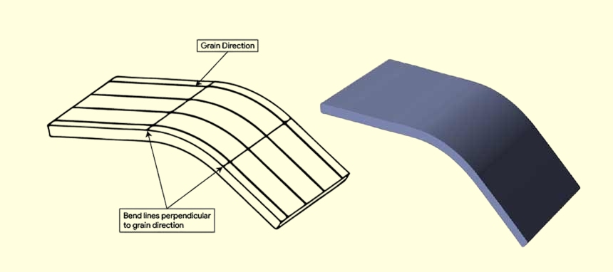
When a metal sheet is rolled, its internal structure elongates along the rolling direction. The resulting alignment defines the grain direction — the path along which most metal crystals are oriented.
Engineers describe bending in three orientations:
- With the grain, the bend line runs parallel to the rolling direction.
- Across the grain – bend line runs perpendicular to rolling direction.
- Diagonal to the grain – bend line runs at an angle, usually around 45°.
Because of this structure, metal sheets become anisotropic — their mechanical properties differ by direction. Across the grain, metals can stretch more before cracking. Along the grain, they’re stiffer but less ductile. Recognizing this anisotropy is key to controlling bending results.
How Rolling Affects Material Properties?
Rolling changes a metal’s internal balance of strength and ductility. Along the rolling direction, tensile strength increases slightly, but elongation (ductility) decreases. In the opposite direction, the metal can withstand more strain before failure.
Typical property variation by direction:
| Material | Strength Variation (Across vs. With Grain) | Ductility Variation |
|---|---|---|
| Mild Steel | ±5–8% | Up to 10% higher across-grain |
| Aluminum 6061-T6 | ±10–15% | Up to 20% higher across-grain |
| Stainless Steel 304 | ±6–10% | Around 10% higher across-grain |
This means that even with identical thickness, tooling, and bend angle, results will vary depending on orientation. In high-tolerance parts, ignoring this factor can lead to visible stress marks or inconsistent geometry.
How Grain Direction Influences Bending Results?
Grain direction directly affects how material fibers stretch on the outside of a bend and compress on the inside. The right direction allows the bend to form smoothly. The wrong one can cause cracking or springback beyond tolerance limits.
| Orientation | Behavior | Typical Result | Recommended Action |
|---|---|---|---|
| With Grain | Easier to bend but less ductile | Higher risk of cracking, rough surface | Use larger inside radius |
| Across Grain | Requires more force, higher ductility | Clean bend, minimal cracking | Preferred for critical parts |
| Diagonal | Moderate characteristics | Acceptable compromise | Keep orientation consistent |
Bending With the Grain
When bending with the grain, metal fibers on the outer edge stretch along their natural alignment. This makes bending easier but less forgiving. The surface may show hairline cracks or dull marks, especially on aluminum and stainless steel.
Problem: High cracking risk and inconsistent angles.
Cause: Grains separate under tension when stretched parallel to rolling.
Solution: Increase the bend radius (1.5–2× thickness) and use softer tempers when possible.
Bending Across the Grain
Across-grain bending is generally stronger and more reliable. The metal’s internal structure evenly resists tension, reducing the risk of cracking and improving bend precision.
Problem: Slightly higher tonnage needed.
Cause: Resistance to deformation increases across grain boundaries.
Solution: Use a standard punch radius and ensure the press capacity can handle a slight increase in tonnage.
Diagonal Bending (45° to Grain)
When part geometry prevents alignment, diagonal bending offers a balanced approach. It combines moderate ductility and acceptable surface quality.
However, production consistency becomes critical. Changing the bend direction even slightly between batches can shift final dimensions or springback angles. Always mark and lock orientation before cutting or nesting.
Key Effects to Consider
Grain direction not only changes how easily metal bends — it affects the part’s strength, accuracy, and finish after forming. Three primary outcomes define how a bend behaves: minimum bend radius, springback, and surface or fatigue performance.
Impact on Minimum Bend Radius
The minimum bend radius determines how tightly a sheet can be bent before cracking.
When bending with the grain, the stretched fibers follow the elongated crystal structure, which weakens the material’s ability to resist tension. Cracks tend to form earlier, especially in more complex alloys. When bending across the grain, the crystal boundaries act like micro-bridges that better distribute stress, allowing tighter bends.
| Orientation | Behavior | Recommended Inside Radius (× Thickness) | Notes |
|---|---|---|---|
| With Grain | Higher cracking risk | 1.5–2.0× | Use softer tempers or larger die radius |
| Across Grain | Better ductility | 0.75–1.0× | Ideal for precision bends and small radii |
| Diagonal | Balanced results | 1.0–1.5× | Acceptable compromise when geometry limits direction |
Example:
For 6061-T6 aluminum, a bend along the grain typically requires a radius of 2.5–3× thickness to avoid cracking, while across-grain bends can hold a clean 1× thickness radius. In mild steel, across-grain bends usually perform well at 1× or less, showing greater flexibility.
Design Tip:
If the layout requires a with-grain bend, increase the radius by at least 50% beyond the standard recommendation, or perform a test bend first to confirm there is no surface cracking.
Influence on Springback and Dimensional Accuracy
Springback — the material’s partial return toward its flat shape after forming — is another area where grain direction matters.
Because metal behaves differently in tension and compression along the grain, bends parallel to it show more rebound and variation. Across-grain bends, where stress distribution is balanced, hold angles more accurately.
| Material | Springback (Across Grain) | Springback (With Grain) | Typical Difference |
|---|---|---|---|
| Mild Steel | 2°–3° | 4°–5° | 1.5–2× higher with grain |
| Stainless Steel | 3°–4° | 5°–6° | Moderate sensitivity |
| Aluminum 6061-T6 | 2° | 5°–6° | Very sensitive |
| Copper | <1° | <1° | Negligible difference |
In precision applications such as control panels or mounting enclosures, even a few degrees of variation can affect fit. By predicting orientation effects, engineers can adjust bend allowance (BA) and bend deduction (BD) values in their CAD designs to achieve consistent angles.
Practical Formula:
Adjusted Bend Deduction = Standard BD × (1 + k),
where k ≈ 0.05 for across-grain and k ≈ 0.12–0.15 for with-grain bends.
Effect on Surface Appearance and Fatigue Life
Surface finish reveals how stress flows during bending. With-grain bends often reveal faint cracks or “orange peel” patterns on the tension side, especially on aluminum or high-strength steel. These small imperfections may seem cosmetic, but they often serve as starting points for fatigue cracks.
Across-grain bends create smoother surfaces with uniform stretch marks, thereby improving fatigue resistance. For example, tests on stainless steel samples showed that across-grain bends survived 25–30% more vibration cycles before visible cracking compared to with-grain bends.
| Property | With Grain | Across Grain |
|---|---|---|
| Crack Visibility | High | Low |
| Cosmetic Quality | Fair | Excellent |
| Fatigue Resistance | Shorter life | Longer life |
| Typical Applications | Non-visible brackets | Structural and visible components |
Material and Process Factors
The degree to which grain direction affects bending varies among materials. Metals with strong directional grain structure, like aluminum and high-strength steel, are highly sensitive, while softer or fine-grain materials are more forgiving.
Grain Sensitivity of Common Metals
| Material | Sensitivity to Grain Direction | Notes |
|---|---|---|
| Mild Steel | Low to Moderate | Can bend both ways; across-grain gives cleaner results |
| Stainless Steel 304 | Moderate | Affects springback more than cracking |
| Aluminum 6061-T6 | High | Cracks easily when bent with grain; annealing helps |
| Copper / Brass | Low | Ductile enough for tight bends in any direction |
| High-Strength Steel (AHSS) | Very High | Needs larger radii and careful orientation control |
Practical Summary:
- For aluminum and AHSS, grain direction must always be verified before forming.
- For stainless steel, focus more on springback correction than cracking.
- For copper and mild steel, orientation is less critical but still affects repeatability.
Influence of Grain Size and Heat Treatment
Grain size plays a significant role in the deformation of metals. Smaller, more uniform grains make the sheet more challenging to crack. Larger grains create stress concentration points, which degrade bend quality.
Processes like annealing, normalizing, or cold working modify grain structure:
- Annealing restores ductility and refines grains, ideal before tight-radius bending.
- Cold working increases strength but also makes the metal more brittle — caution needed for sharp bends.
- Aging treatments in aluminum alloys can re-harden the material, requiring adjusted radii.
Example:
A 6061 aluminum sheet in T6 temper may crack at 2× thickness radius along the grain, while the same alloy in O temper (annealed) can bend to 0.75× across the grain without failure.
Press Force and Tooling Considerations
Across-grain bending requires slightly more force because the metal resists deformation along its natural grain.
This typically means a 5–10% increase in press tonnage compared with with-grain bends. For instance, if a job requires 40 tons of grain, across-grain bending might need 44–45 tons.
Tooling Guidelines:
- Use larger die openings and radii for with-grain bends.
- Use standard or tighter radii for across-grain bends to maintain precision.
- Always check press tonnage and record actual readings for process consistency.
Engineering Tip:
Avoid mixing parts with different orientations under the same tooling setup. Slight differences in tonnage and springback can cause variations in final dimensions — especially noticeable in assemblies or mating components.
Design and Production Planning
Grain direction control doesn’t happen by chance — it’s the result of good planning, clear communication, and disciplined workflow. When handled properly, it ensures each bend looks identical across hundreds of parts, regardless of shift or operator.
Marking and Controlling Grain Direction
The first step is visibility. Every rolled sheet comes with a natural grain orientation, often marked by arrows or text from the supplier. Before cutting, that direction should be verified and carried forward into every step of production.
In the design phase, engineers should always:
- Add a grain direction arrow (→) to drawings and 3D models.
- Note the desired orientation in the title block (“Bend Across Grain” or “Bend With Grain”).
- Communicate special requirements during pre-production meetings.
In the fabrication phase:
- Machine operators should verify sheet markings before loading.
- Nesting software should have orientation lock enabled to prevent rotation during part arrangement.
- Cut blanks should be labeled with printed arrows or color-coded tape for easy identification.
| Stage | What to Check | Responsible |
|---|---|---|
| Material Receiving | Verify rolling direction markings | Quality / Warehouse |
| CAD Design | Add direction arrows and notes | Engineer |
| Nesting & Cutting | Lock grain orientation during nesting | CAM Programmer |
| Bending Setup | Confirm bend direction vs. marking | Press Operator |
Pro Tip:
During press brake setup, keep one labeled master blank nearby. This visual reference prevents mix-ups between shifts and ensures every batch aligns the same way.
Integrating Grain Direction into Process Flow
A strong process flow connects design intent to shop-floor execution. Each step must confirm that grain orientation stays consistent from sheet to finished part.
A simplified workflow:
- Material Verification – Inspect incoming sheets and document grain direction.
- Blank Cutting – Maintain arrow alignment when stacking or labeling parts.
- Bending Preparation – Review CAD notes and confirm tooling setup matches orientation.
- Forming and Inspection – Bend a test piece, check for cracks or springback deviation, and record the data.
- Feedback and Adjustment – If distortion appears, adjust the bend radius or direction for the next batch.
This traceable loop builds a foundation for consistent quality control. If a cracking issue occurs, you can trace it to a specific batch or setup rather than guessing.
Balancing Performance and Efficiency
In real-world production, the “ideal” direction doesn’t always fit the nesting layout. Sometimes rotating parts with the grain saves material or allows more pieces per sheet. Rather than rejecting this option outright, engineers can find a balance between quality and efficiency.
| Objective | Across Grain | With Grain |
|---|---|---|
| Strength & Fatigue Life | Excellent | Moderate |
| Cosmetic Finish | Smooth | Slightly rougher |
| Material Yield | Slightly lower | Higher (better nesting) |
| Tonnage Required | +5–10% | Lower |
| Risk of Cracking | Low | Higher |
Example:
If rotating a chassis panel saves 10% material waste but forces a with-grain bend, compensate by:
- Increasing the bend radius by 50%.
- Using softer temper or annealed sheets.
- Performing a quick test bend to confirm results.
The goal is to make orientation a controlled trade-off rather than a hidden variable. Balancing these factors ensures maximum yield without sacrificing reliability.
Standardizing Documentation and Quality Checks
Every part that undergoes bending should have traceable documentation showing:
- Material type and thickness.
- Grain direction arrow or notation.
- Required bend radius and orientation.
- Press brake settings used (tonnage, die width, punch radius).
This allows operators and inspectors to replicate results easily in future batches. Some manufacturers include a grain direction icon in their internal ERP or traveler sheets — a small but effective way to prevent wrong-direction bending.
Practical Example:
At Shengen, engineers often include “GR → ACROSS” on drawings and require operators to initial verification before forming. This habit eliminates mix-ups, improves cross-shift communication, and strengthens quality control records.
Conclusion
Grain direction directly affects bending quality. Bending with the grain can cause cracks and uneven angles, while bending across the grain gives smoother, firmer, and more consistent results. Controlling grain direction from design to production helps avoid rework and ensures better part performance.
At Shengen, we help you choose the right bend direction and setup for each project. Please send us your drawings, and our engineers will review them to ensure clean bends, accurate angles, and reliable quality.
Hey, I'm Kevin Lee

For the past 10 years, I’ve been immersed in various forms of sheet metal fabrication, sharing cool insights here from my experiences across diverse workshops.
Get in touch
Kevin Lee
I have over ten years of professional experience in sheet metal fabrication, specializing in laser cutting, bending, welding, and surface treatment techniques. As the Technical Director at Shengen, I am committed to solving complex manufacturing challenges and driving innovation and quality in each project.
Related Resource

Fingerprint Resistant Stainless Steel: How It Works,and How to Choose


