La fabricación de piezas de precisión plantea retos constantes. Los ingenieros y diseñadores a menudo necesitan ayuda para conseguir tolerancias ajustadas manteniendo unos costes manejables. El fresado periférico ofrece una solución al combinar una gran precisión con un arranque de material eficaz, pero muchos profesionales aún tienen que decidir cuándo utilizar esta técnica frente a otros métodos de mecanizado.
Las siguientes secciones resumen todo lo que los profesionales técnicos necesitan saber sobre el fresado periférico, desde los conceptos fundamentales hasta las estrategias de optimización avanzadas. Examinaremos aplicaciones del mundo real y consejos prácticos extraídos de décadas de experiencia en mecanizado.
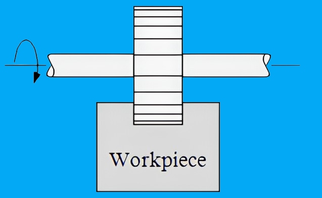
¿Qué es el fresado periférico?
El fresado periférico es un proceso de corte en el que el diámetro exterior de la herramienta realiza la acción de corte primaria. Los filos de corte giran perpendicularmente a la superficie de la pieza, eliminando material de forma controlada. Esta técnica proporciona excelentes acabados superficiales y un estricto control dimensional, por lo que resulta ideal para componentes de precisión.
Comprender los fundamentos del fresado periférico
El corte de metales requiere un control preciso y profundos conocimientos técnicos. El proceso de fresado periférico ofrece ventajas únicas que lo diferencian de los métodos de mecanizado tradicionales. Examinemos los conceptos básicos que hacen poderosa esta técnica.
Diferencias entre el fresado periférico y otras técnicas de fresado
Las operaciones de fresado varían en su forma de trabajar con el material de la pieza. Cada método sirve para fines específicos y ofrece ventajas distintas para diferentes escenarios de fabricación.
Fresado frontal vs. Fresado periférico
Fresado frontal:
- Utiliza la cara frontal de la fresa para eliminar grandes cantidades de material rápidamente, ideal para crear superficies planas en piezas grandes como placas base y componentes estructurales.
- Crea superficies horizontales con una rugosidad típica de Ra 1,6-3,2 micrómetros, adecuadas para la mayoría de las aplicaciones industriales.
- Requiere mayor potencia debido a la mayor área de contacto, normalmente 20-30% más consumo de energía que el fresado periférico.
Fresado periférico:
- Emplea el diámetro exterior de la fresa para conseguir cortes verticales precisos y contornos complejos, perfectos para crear características detalladas y componentes de precisión
- Produce acabados superficiales superiores con valores de rugosidad tan bajos como Ra 0,4 micrómetros mediante parámetros de corte optimizados.
- Ofrece una excelente evacuación de la viruta gracias a la zona de corte focalizada, lo que reduce la acumulación de calor y prolonga la vida útil de la herramienta.
Ranurado y fresado de perfiles Comparación
Características de ranurado:
- Exige un acoplamiento total de la herramienta, lo que aumenta las fuerzas de corte hasta 300% en comparación con el fresado de perfiles, lo que requiere una selección de herramientas robusta.
- Requiere una potencia de máquina significativa y configuraciones rígidas para manejar las mayores cargas de corte y mantener la precisión.
- Limitada a cortes rectos, pero alcanza velocidades máximas de arranque de material de hasta 100 pulgadas cúbicas por minuto en aluminio.
Ventajas del fresado de perfiles:
- Utiliza un acoplamiento parcial de la herramienta (normalmente 30-60% del diámetro de la herramienta) para mejorar el control y reducir las fuerzas de corte.
- Mantiene temperaturas de funcionamiento más bajas gracias a la interrupción de la acción de corte, lo que prolonga la vida útil de la herramienta hasta 50%
- Capaz de producir formas 3D complejas con tolerancias tan ajustadas como ±0,0005 pulgadas
Componentes principales del fresado periférico
El éxito depende de la correcta selección y configuración de los equipos. Cada componente desempeña un papel fundamental en la consecución de los resultados deseados.
La herramienta de corte: Tipos y características
Características avanzadas de las herramientas:
- Molinos de extremo: Herramientas versátiles con 2-8 canales, que ofrecen ángulos de hélice de 30-45 grados para una óptima evacuación de la viruta y eficacia de corte.
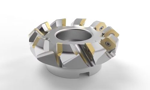
- Molinos de conchas: Fresas de gran diámetro (2-12 pulgadas) con plaquitas intercambiables, que ofrecen soluciones rentables para el arranque de material pesado.
- Fresas helicoidales: Herramientas especializadas con ángulos de hélice progresivos (35-50 grados) para reducir las vibraciones y mejorar el acabado superficial.
- Fresas de punta esférica: Herramientas de precisión para contornos 3D, disponibles con radios de 0,5-25 mm para varios niveles de detalle
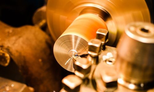
Tipos de técnicas de fresado periférico
La selección de la técnica de fresado adecuada repercute directamente en la calidad de la pieza, la vida útil de la herramienta y la eficacia de la producción. Cada método ofrece ventajas específicas para distintos escenarios de fabricación. A continuación se analizan en profundidad los principales enfoques.
Fresado periférico convencional
El fresado convencional desplaza la herramienta en sentido contrario al avance de la pieza. La fresa entra en el material con un espesor de viruta cero y sale con un espesor máximo. Este enfoque beneficia a las máquinas con problemas de holgura o cuando se trabaja con materiales de superficie dura.
Fresado periférico de ascenso
El fresado de escalonamiento invierte la rotación de la herramienta con respecto al sentido de avance. La fresa entra con el máximo espesor de viruta y sale a cero. Este método reduce el desgaste de la herramienta, mejora el acabado superficial y requiere menos fuerza de corte. Las máquinas CNC modernas suelen utilizar por defecto el fresado ascendente para la mayoría de las aplicaciones.
Fresado periférico de alta velocidad
Las técnicas de alta velocidad llevan las velocidades de corte más allá de los límites tradicionales. Este enfoque reduce las fuerzas de corte y la generación de calor, al tiempo que aumenta la velocidad de arranque de material. El proceso exige herramientas rígidas y un control preciso de la máquina, pero proporciona un aumento excepcional de la productividad.
Microfresado periférico
El microfresado funciona a escalas en miniatura con herramientas especializadas. El proceso crea características que se miden en micras manteniendo tolerancias muy ajustadas. Esta técnica se emplea en sectores como la fabricación de dispositivos médicos y la electrónica de precisión.
Opciones de material de la herramienta
La selección del material de la herramienta determina el rendimiento y la rentabilidad del mecanizado. Los materiales avanzados amplían las posibilidades de las aplicaciones más exigentes. La elección correcta equilibra el coste, la durabilidad y la capacidad de corte.
Acero de alta velocidad (HSS)
Las herramientas HSS ofrecen soluciones rentables para tareas básicas de mecanizado. Estas herramientas mantienen la dureza a temperaturas moderadas y resisten el desgaste durante las operaciones estándar. Su tenacidad las hace adecuadas para cortes interrumpidos y condiciones de mecanizado variables.
Herramientas de metal duro
El metal duro define el estándar del mecanizado moderno de alto rendimiento. Estas herramientas combinan una dureza extrema con una buena tenacidad. Su estabilidad térmica permite mayores velocidades de corte, mientras que su resistencia al desgaste prolonga la vida útil de la herramienta en aplicaciones exigentes.
Herramientas diamantadas
Los recubrimientos de diamante superan los límites del rendimiento en aplicaciones específicas. Su dureza suprema hace frente a materiales abrasivos como el grafito y la cerámica. El recubrimiento reduce la fricción y la generación de calor durante los cortes, aunque los costes limitan su uso a escenarios especializados.
Técnicas y mejores prácticas
Dominar el fresado periférico requiere un profundo conocimiento de los parámetros de corte y el control del proceso. Estas directrices técnicas ayudan a conseguir un rendimiento óptimo al tiempo que se prolonga la vida útil de la herramienta.
Parámetros óptimos de corte
La selección precisa de los parámetros es uno de los principales factores que influyen en el éxito y la productividad del mecanizado. Equilibrar estos elementos garantiza una calidad constante de las piezas y una producción eficiente.
Velocidad del cabezal y avance
Cálculos de velocidad y optimización:
- Calcular la velocidad de corte óptima utilizando factores de velocidad específicos del material (V = π × D × N ÷ 12).
- Adaptación de las revoluciones del husillo al diámetro de la herramienta y a las propiedades del material
- Aluminio: 800-1500 SFM
- Acero: 300-600 SFM
- Inoxidable: 150-400 SFM
- Titanio: 100-300 SFM
Determinación de la velocidad de avance:
- Cálculo de la carga de viruta en función de la dureza del material y del diámetro de la herramienta
- Materiales blandos: 0,004-0,008 pulgadas por diente
- Materiales duros: 0,001-0,003 pulgadas por diente
- Ajustar el número de canales y los requisitos de acabado superficial
- Control del consumo de energía para optimizar la velocidad de alimentación
Profundidad y anchura de corte
Estrategias de profundidad de corte:
- Desbaste: 1,0-1,5 veces el diámetro de la herramienta para un arranque máximo de material
- Refinamiento: 0,2-0,5 veces el diámetro de la herramienta para la calidad de la superficie
- Ajuste en función de la rigidez de la máquina y las propiedades del material
- Considerar la desviación de la herramienta a distintas profundidades de corte
Gestión de la anchura de corte:
- Mantiene el enganche radial 30-60% para un corte estable
- Reducir la anchura para materiales más complejos y herramientas más extensas
- Aumente la anchura para obtener la máxima productividad en condiciones estables
- Calcular la anchura máxima en función de la potencia disponible del husillo
Estrategias de evacuación de chips
Una gestión adecuada de las virutas evita que se vuelvan a cortar y garantiza unas condiciones de corte uniformes.
Uso del refrigerante
Técnicas de aplicación:
- Refrigerante de alta presión (500-1000 PSI) para bolsas profundas
- Posicionamiento directo de la boquilla en la zona de corte
- Cálculo del caudal en función de los parámetros de corte
- Control de la concentración de refrigerante (8-12% para la mayoría de las aplicaciones)
Sistemas de chorro de aire
Directrices de aplicación:
- Requisitos mínimos de presión de 90 PSI
- Posicionamiento múltiple de las boquillas para una cobertura completa
- Normas de calidad del aire comprimido (ISO 8573-1)
- Integración con sistemas MQL para un rendimiento óptimo
Minimizar el desgaste de la herramienta
Ampliamos la vida útil de las herramientas mediante el control y la supervisión estratégicos de los procesos.
Optimización de sendas
Estrategias de programación:
- Trayectorias de herramienta trocoidales para una carga de viruta constante
- Ajuste dinámico del avance en las curvas
- Optimización de la ruta de entrada/salida
- Evite los cambios bruscos de dirección
- Mantener constante la carga de viruta mediante la optimización CAM
Técnicas de gestión del calor
Métodos de control de la temperatura:
- Técnicas de corte por impulsos para disipar el calor
- Sistemas estratégicos de suministro de refrigerante
- Control térmico mediante sensores de husillo
- Selección del revestimiento en función de las propiedades térmicas
- Periodos de descanso para la estabilidad térmica en trabajos de precisión
Conclusión
El fresado periférico es un proceso de mecanizado fundamental en la fabricación moderna. Desde componentes aeroespaciales hasta dispositivos médicos, esta técnica proporciona la precisión y la calidad superficial que exige la industria. El proceso sigue evolucionando con nuevas herramientas y tecnologías.
Los maquinistas profesionales alcanzan el éxito mediante una cuidadosa selección de parámetros y unas prácticas de mantenimiento coherentes. La selección adecuada de herramientas, las estrategias de corte y la capacidad de resolución de problemas proporcionan resultados fiables. Estos fundamentos permanecen constantes incluso a medida que avanza la tecnología.
Hola, soy Kevin Lee

Durante los últimos 10 años, he estado inmerso en diversas formas de fabricación de chapa metálica, compartiendo aquí ideas interesantes de mis experiencias en diversos talleres.
Póngase en contacto

Kevin Lee
Tengo más de diez años de experiencia profesional en la fabricación de chapas metálicas, especializada en corte por láser, plegado, soldadura y técnicas de tratamiento de superficies. Como Director Técnico de Shengen, me comprometo a resolver complejos retos de fabricación y a impulsar la innovación y la calidad en cada proyecto.

