구멍 하나가 사소해 보일 수 있지만 판금 제조에서는 전체 생산 속도를 결정할 수 있습니다. 구멍 하나가 잘못 배치되거나 크기가 작으면 벤딩이 왜곡되거나 공구가 손상되거나 조립이 지연될 수 있습니다. 반대로 잘 설계된 홀은 기계 시간을 단축하고 부품의 정렬을 유지하며 전체 수율을 향상시킵니다.
대부분의 제작 문제는 절삭이 시작되기 훨씬 전에 CAD 모델 내부에서 시작됩니다. 엔지니어는 적절한 홀 치수, 간격 및 공차를 조기에 설정함으로써 부품을 더 쉽게 생산하고 나중에 재작업을 줄일 수 있습니다.
이 문서에서는 판금 홀 설계의 기본 원리를 살펴보고 형상, 재료 거동 및 공정 제한이 어떻게 상호 작용하여 품질과 효율성을 모두 달성하는지 설명합니다.
판금 설계를 위한 구멍 대 두께 비율 가이드라인
간단하지만 강력한 규칙이 대부분의 프로젝트에 적용됩니다:
💡 디자인 팁: 구멍 지름을 재료 두께와 최소한 같게 유지합니다.
예를 들어, 1.5mm 알루미늄 판재에서 가장 작은 안전 구멍은 Ø 1.5mm입니다. 더 작아지면 펀칭 압력이 급격히 증가하고 더 많은 버가 발생하며 펀치 수명이 단축됩니다. 스테인리스 스틸과 같이 더 단단한 소재는 균열이나 공구 휨을 방지하기 위해 두께의 약 1.5배에 달하는 더 큰 비율이 필요합니다.
| 재료 종류 | 일반적인 두께(mm) | 최소 구멍 Ø(mm) | 실용적인 참고 사항 |
|---|---|---|---|
| 알류미늄 | 1.0 - 3.0 | 두께 ≥ | 깨끗한 가장자리, 낮은 톤수 |
| 온화한 강철 | 1.0 - 4.0 | 두께 ≥ 1.2 × 두께 | 균형 잡힌 성형 동작 |
| 스테인레스 스틸 | 0.8 - 3.0 | ≥ 1.5 × 두께 이상 | 균열 방지, 공구 수명 연장 |
| 구리 / 황동 | 1.0 - 2.5 | 두께 ≥ | 날카로운 도구가 필요합니다. |
작은 편차도 비용을 증가시킬 수 있습니다. 권장보다 작은 구멍 20%를 펀칭하면 펀치 수명이 40% 감소할 수 있습니다. 작은 구멍이 필요한 장식 또는 환기 패턴에 적합합니다, 레이저 절단 를 사용하는 것이 바람직하지만 사이클 시간이 느려지고 검사 노력이 증가할 수 있습니다.
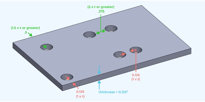
구멍 배치 및 가장자리 거리 가이드라인
홀 위치는 외관과 성형 신뢰성 모두에 영향을 미칩니다. 구멍이 가장자리에 너무 가깝거나 구부러지면 금속이 고르지 않게 늘어나 압력을 받으면 금이 갈 수 있습니다.
| 특징 | 최소 거리 | 목적 |
|---|---|---|
| 구멍 → 가장자리 | ≥ 1.5 × 두께 이상 | 찢어짐 방지 |
| 구멍 → 구부러진 선 | 두께 ≥ 2 × 두께 | 왜곡 방지 |
| 구멍 → 구멍 | 2 × 구멍 지름 ≥ 2 | 강성 유지 |
⚠️ 일반적인 오류: 1mm 시트의 구부러진 부분에서 2mm 미만 떨어진 곳에 장착 구멍을 배치하면 성형 중에 찢어지는 경우가 많습니다.
수정: 구멍을 바깥쪽으로 2~3mm 이동하거나 구부러진 선 근처에 릴리프 컷을 추가합니다.
힌지 플랜지와 같이 타이트한 레이아웃이 불가피한 경우 벤딩 후 2차 드릴링으로 더 깔끔한 결과를 얻을 수 있습니다. 한 생산 사례에서는 벤딩 라인 절단에서 구멍 패턴을 2mm 더 멀리 이동하는 것만으로도 찢어짐 결함이 30% 감소하여 몇 시간의 수동 재작업 시간을 절약할 수 있었습니다.
비용 효율적인 제작을 위한 허용 오차 계획 수립
정밀도에는 항상 시간이 걸립니다. 현실적인 허용 오차를 설정하면 생산 공정에서 정확성과 경제성을 모두 보장할 수 있습니다.
| 홀 기능 | 실제 허용 오차(mm) | 제작 방법 |
|---|---|---|
| 일반 장착 구멍 | ± 0.15 | 펀칭 또는 레이저 커팅 |
| 하드웨어 구멍(PEM 너트/리벳) | ± 0.08 | 깨끗한 가장자리 필요 |
| 위치/얼라인먼트 구멍 찾기 | ± 0.03 | 필요한 경우 2차 리밍 |
최적의 기능을 보장하기 위해 필요한 경우에만 가장 엄격한 공차를 사용하십시오. 중요하지 않은 구멍을 완화하면 총 검사 시간과 공구 마모를 10~15 % 줄일 수 있습니다. 가장 좋은 방법은 CAD 파일에 홀 유형과 공차를 태그하여 제작자가 정밀도가 필요한 홀과 그렇지 않은 홀을 즉시 파악할 수 있도록 하는 것입니다.
💡 디자인 팁: 구멍을 다음과 같이 표시하십시오. 클리어런스, 탭, 또는 프레스 핏 에 직접 입력하세요. 이 하나의 노트로 제작 중에 여러 개의 이메일을 저장할 수 있습니다.
CAD에서 실제 제작까지
화면에서는 완벽해 보이는 도면이 실제에서는 실패할 수 있습니다. 예를 들어, 플랜지를 따라 늘어선 M3 구멍은 시트가 형성된 후 굽힘 반경과 겹쳐 정렬이 왜곡될 수 있습니다. 패턴을 바깥쪽으로 1mm만 조정하면 손상을 방지하고 부드러운 구부림을 유지할 수 있습니다.
도면을 해제하기 전에 평면 패턴을 펼쳐서 가장자리와 구부러진 부분을 기준으로 구멍 간격을 확인합니다. 이 빠른 확인을 통해 스크랩 및 후반 단계의 드릴링을 방지할 수 있습니다.
⚙️ 빠른 규칙: 승인 전에 가장 작은 구멍 + 가장 가까운 굽힘 거리 ≥ 2 × 시트 두께를 검토합니다.
CAD에서 1밀리미터의 선견지명은 작업 현장에서 몇 분의 시간 절약으로 이어집니다.
재료 거동 및 홀 품질
금속마다 절삭 및 성형력에 다르게 반응합니다. 알루미늄은 낮은 톤수로도 깔끔하게 절단됩니다. 스테인리스 스틸은 더 높은 압력과 더 날카로운 펀치가 필요합니다. 아연도금강은 간격을 +0.1mm 늘리지 않으면 가장자리 아연 코팅이 벗겨질 수 있습니다. 구리와 황동은 부드럽지만 끈적거려서 윤활과 공구 세척이 필요합니다.
두께가 3mm를 초과하면 버 높이가 빠르게 증가합니다. 항상 다음 사항을 계획하세요. 디버링 또는 마무리 노트의 모따기. 이 단계를 따르지 않으면 조립 과정에서 코팅 결함, 하드웨어 장착 불량 또는 작업자 부상을 초래할 수 있습니다.
⚠️ 일반적인 오류: 파우더 코팅 중에 버가 "타버릴 것"이라고 가정하면 나중에 코팅 기포가 발생하거나 하드웨어에 맞지 않는 경우가 많습니다.
💡 디자인 팁: 일관된 품질을 위해 도면의 일반 메모에 "코팅하기 전에 모든 가장자리와 구멍을 디버링하십시오"를 포함하세요.
하드웨어 홀 및 조립 맞춤
대부분의 판금 구멍은 하드웨어를 고정하거나 어셈블리를 정렬하는 한 가지 용도로 설계됩니다.
치수가 조금이라도 어긋나면 나사가 걸리거나 리벳이 회전하거나 패널이 잘못 정렬됩니다.
가장 좋은 해결책은 가능한 한 설계 프로세스 초기에 표준 패스너 간극 차트를 따르는 것입니다.
예를 들어, M3 나사는 3.2mm, M4 → 4.3mm, M5 → 5.3mm의 여유 구멍이 필요합니다. 리벳 너트나 셀프 클렌칭 스터드와 같은 하드웨어는 하드웨어 본체의 직경보다 약 0.1~0.2mm 정도 큰 약간 큰 크기의 구멍이 필요합니다. 이 작은 마진 덕분에 공구 자국이나 코팅 긁힘 없이 쉽게 압입할 수 있습니다.
💡 디자인 팁: 항상 CAD에서 홀 유형을 지정하십시오.클리어런스, 탭, 또는 누릅니다.
이 단일 메모는 작업 현장의 혼란을 방지하고 생산 과정에서 주고받는 커뮤니케이션의 필요성을 없애줍니다.
⚠️ 일반적인 오류: 모든 하드웨어 구멍에 "꼭 맞음"을 사용하면 코팅 후 프레스 핏이 실패할 수 있습니다.
라벨링 기능을 사용하면 이러한 비용이 많이 드는 감독을 확실히 피할 수 있습니다.
또한 일관된 홀 표기는 검사 속도를 높이고 작업자가 추측 없이 올바른 도구를 사용할 수 있도록 도와줍니다.
다중 부품 어셈블리의 홀 정렬
여러 개의 패널이 결합된 경우 0.3mm의 오프셋만 있어도 나사가 맞지 않을 수 있습니다. 구멍이 잘못 정렬되면 수동으로 다시 드릴링해야 하고 코팅이 손상되며 생산 리듬이 깨집니다.
좋은 정렬은 CAD 단계에서 시작됩니다:
기준 구멍은 서로가 아닌 공통 기준점 또는 가장자리를 기준으로 합니다. 이렇게 하면 시트 두께나 굽힘이 약간 달라져도 일관성을 유지할 수 있습니다. 대형 인클로저의 경우 파일럿 구멍을 추가하거나 조립 중에 정렬을 안내하는 탭을 배치하는 것이 좋습니다.
여러 부품에 공차가 누적되는 경우 한쪽의 간격을 약간(일반적으로 +0.2mm) 늘려 작은 위치 오차를 흡수합니다. 이러한 설계 유연성 덕분에 생산 라인에서 픽스처를 조정할 필요가 없는 경우가 많습니다.
💡 디자인 팁: 도면을 공개하기 전에 3D CAD에서 조립을 시뮬레이션하세요.
5분의 점검으로 조립 후 몇 시간의 재작업을 방지할 수 있습니다.
결과: 더 매끄러운 정렬, 더 빠른 설치, 더 적은 불량 부품.
머티리얼 동작 및 홀 성능
금속마다 절삭 및 성형 힘에 반응하는 방식이 다릅니다. 각각의 동작 방식을 알면 엔지니어가 구멍의 품질과 공구 마모를 예측하는 데 도움이 됩니다.
| 소재 | 일반적인 홀 동작 | 권장 조정 |
|---|---|---|
| 알류미늄 | 낮은 버로 깔끔하게 절단 | 1× 두께 이상의 구멍 |
| 스테인레스 스틸 | 딱딱하고, 찌그러지거나 깨질 수 있음 | 1.5× 두께 이상의 구멍 |
| 아연 도금 강판 | 아연 코팅이 벗겨질 수 있습니다. | + 0.1mm 여유 공간 추가 |
| 황동 / 구리 | 부드럽지만 끈적임 | 윤활 처리된 날카로운 도구 사용 |
⚠️ 일반적인 오류: 스테인리스 스틸에 구멍을 너무 조밀하게 설계하면 펀치가 빠르게 무뎌지고 버 높이가 높아집니다. 구멍 크기를 0.1mm만 늘려도 공구 수명을 25 % 연장할 수 있습니다.
3mm 이상의 두꺼운 시트는 버가 더 심하게 발생하는 경향이 있습니다. 도면에서 디버링 또는 모따기를 지정하여 가장자리를 깨끗하게 유지하고 코팅 결함을 방지합니다.
표면 마감 및 코팅 효과
코팅은 많은 사람들이 예상하는 것 이상으로 구멍 크기에 큰 영향을 미칠 수 있습니다. 분체 도장 는 측면당 60~120µm를 추가하고, 아노다이징은 10~25µm를 추가합니다. 보정하지 않으면 마감 처리가 적용된 후 하드웨어가 더 이상 맞지 않을 수 있습니다.
| 표면 마감 | 일반적인 두께(µm) | 권장 구멍 조정 |
|---|---|---|
| 분말 코팅 | 60 - 120 | + 0.1 ~ + 0.2mm |
| 아노다이징 | 10 - 25 | + 0.05 mm |
| 아연 도금 | 5 - 15 | 사소한 변경 사항 |
| 습식 페인트 / 프라이머 | 30 - 50 | + 0.1 mm |
💡 디자인 팁: 간격이 중요한 경우 코팅 중에 기능성 구멍을 마스킹합니다. 이 간단한 단계를 통해 치수 정확도를 유지하고 조립 속도를 높일 수 있습니다.
⚠️ 일반적인 오류: 코팅 허용치를 추가하는 것을 잊어버리면 마감 후 수작업으로 드릴링해야 하므로 외관과 비용 관리를 망치는 지름길이 됩니다.
코팅 두께를 적절히 계획하면 정밀한 조립을 보장하고 처리 후 폐기물을 방지할 수 있습니다.
강도, 피로 및 구조적 무결성
모든 구멍은 주변 금속을 약간 약화시킵니다. 장력이나 진동이 가해지면 가장자리에 응력이 집중되어 피로 균열이 발생할 수 있습니다. 설계자는 용접부나 가장자리에서 두 장 두께의 구멍을 유지하여 이를 관리할 수 있습니다. 하중을 받는 부위의 경우 플랜지나 칼라를 추가하여 강성을 회복할 수 있으며, 테스트 결과 국부 강성을 최대 30%까지 높일 수 있는 것으로 나타났습니다.
💡 디자인 팁: 브래킷과 장착 지점에는 플랜지 또는 칼라 구멍을 사용합니다. 두께나 무게를 늘리지 않고도 부품을 강화할 수 있습니다.
진동은 또 다른 숨겨진 위협입니다. 시간이 지남에 따라 움직이면 구멍이 커지고 패스너가 느슨해집니다. 와셔, 부싱 또는 나사 인서트를 사용하면 하중이 분산되고 서비스 수명이 향상됩니다. 자주 열어야 하는 패널이나 도어에서는 리벳 너트가 태핑 시트 구멍보다 성능이 뛰어나 반복 사용 시 내구성을 보장합니다.
결과: 내피로성 향상, 제품 수명 연장, 유지보수 문제 감소.
더 빠르고 저렴한 제작을 위한 스마트 DFM 전략
구멍을 효율적으로 설계하는 것은 기능 저하 없이 생산 비용을 절감할 수 있는 가장 간단한 방법 중 하나입니다. 직경, 간격, 홀 그룹화 등 작은 선택만으로도 작업 현장에서 눈에 띄는 차이를 만들 수 있습니다.
먼저 기존 펀치 및 드릴 비트와 일치하는 표준 구멍 크기(예: 3.0, 3.5, 4.0mm)를 0.5mm 단위로 사용하는 것부터 시작하세요. 따라서 특별한 툴링이 필요하지 않고 설정 시간이 단축되며 제작자가 다양한 부품에 동일한 툴링을 활용할 수 있습니다. 또한 표준화는 네스팅 효율성과 CNC 프로그래밍 속도를 향상시킵니다.
💡 디자인 팁: 여러 구성 요소에 동일한 구멍 크기를 사용하세요. 이를 통해 공급업체는 더 적은 도구 변경과 더 빠른 설정으로 제품을 실행할 수 있습니다.
무작위로 구멍을 배치하지 말고 부품 형상에 맞춰 직선 또는 격자를 따라 구멍을 그룹화하세요. 효율적인 홀 그룹화는 공구 이동 시간을 단축하여 기계가 더 적은 스트로크로 각 패스를 완료할 수 있도록 도와줍니다. 또한 구멍 행을 굽힘 방향과 평행하게 정렬하면 변형을 방지하고 성형 중에 부품을 평평하게 유지할 수 있습니다.
⚠️ 일반적인 오류: 구멍이 흩어져 있으면 펀칭 시간이 느려지고 성형 후 평탄도가 고르지 않게 됩니다. 체계적인 홀 패턴은 시간과 재료 정렬 문제를 모두 줄여줍니다.
마지막으로 CAD 모델에서 기능하지 않는 구멍이 있는지 검토합니다. 불필요한 피처는 절단, 청소 및 품질 검사에 드는 비용을 증가시킵니다. 홀 수를 201개만 줄여도 총 기계 시간을 101개까지 단축할 수 있으며, 이는 대량 생산에서 그 절감 효과가 빠르게 배가됩니다.
프로토타입에서 생산까지: 진화하는 홀 디자인
프로젝트가 프로토타입에서 대량 생산 단계로 넘어가면서 홀 요구 사항이 달라집니다. 초기 단계의 프로토타입은 유연성을 우선시하는 반면, 생산은 일관성과 속도에 중점을 둡니다.
| 생산 단계 | 주요 목표 | 홀 전략 |
|---|---|---|
| 프로토타입 | 디자인 테스트, 빠른 수정 | 위치 조절이 가능한 레이저 커팅 홀 |
| 파일럿 / 브리지 런 | 세분화 및 반복성 | 크기 표준화, 하드웨어 적합성 테스트 |
| 대량 생산 | 효율성 및 내구성 | 반복적인 구멍에 고정 펀치 툴링 사용 |
예를 들어, 프로토타입 인클로저에는 M3 나사를 위해 12개의 3.3mm 레이저 커팅 홀이 사용될 수 있습니다. 검증 후 표준 3.2mm 펀칭 구멍으로 전환하면 디버링 단계가 제거되고 부품당 약 8초가 절약됩니다. 500개 배치의 경우, 이는 설계 의도를 변경하지 않고도 1시간 이상의 기계 시간을 절약할 수 있는 시간입니다.
💡 디자인 팁: 적합성과 기능이 확인되면 홀 형상을 고정합니다. 툴링 효율성은 설계 안정성에 따라 달라집니다.
브리징 설계 및 제작
좋은 홀 설계는 단순한 형상이 아니라 커뮤니케이션입니다. 홀의 목적, 크기 및 공차를 명확하게 정의하는 도면은 제작자가 툴링, 이송 속도 및 네스팅을 최적화하는 데 도움이 됩니다.
생산 전에 공급업체와 함께 간단한 DFM 검토를 실행하세요. 이를 통해 간격이 가까운 구멍을 슬롯에 병합하거나 펀치 피치에 맞게 구멍 간격을 조정하는 등 빠른 개선 사항을 발견하는 경우가 많습니다. 이러한 조정을 통해 기능을 유지하면서 사이클 시간을 단축할 수 있습니다.
⚙️ 빠른 규칙: 홀 레이아웃을 설명하는 것보다 가공하는 데 시간이 더 오래 걸린다면 DFM 점검이 필요한 때입니다.
코팅 두께, 하드웨어 브랜드 또는 조립 순서를 공유하면 나중에 예상치 못한 문제를 방지할 수 있습니다. 꽉 끼임, 코팅 막힘, 공구 마모 등 구멍과 관련된 많은 문제는 잘못된 설계가 아니라 디테일이 누락된 데서 비롯됩니다.
일반적인 홀 디자인 실수 및 수정 사항
| 디자인 이슈 | 원인/위험 | 고치다 |
|---|---|---|
| 가장자리 또는 구부러진 부분에 너무 가까운 구멍 | 성형 중 찢어짐 또는 갈라짐 발생 | 구부러진 부분이나 가장자리에서 1.5-2배 이상의 두께를 유지하세요. |
| 허용 오차가 너무 좁음 | 검사 비용 증가, 생산 속도 저하 | 중요하지 않은 경우 ±0.15-0.20mm로 여유를 둡니다. |
| 코팅 허용치 무시 | 완료 후 하드웨어가 맞지 않습니다. | 0.1-0.2mm 여유 공간 추가 |
| 비표준 구멍 크기 | 맞춤형 펀치 또는 드릴 필요 | 표준 시리즈(3.0, 4.0, 5.0mm) 사용 |
| 레이블이 없는 구멍 유형 | 잘못된 프로세스 또는 도구 선택 | "여유 공간", "탭" 또는 "누름"으로 태그 지정 |
⚠️ 일반적인 오류: 기능 구멍에 라벨을 붙이지 않으면 태핑, 드릴링, 클리어런스 작업 간에 혼동이 생기며, 이는 조립할 때만 발견되는 경우가 많습니다. 명확한 문서화는 시간, 부품, 좌절감을 줄여줍니다.
결론
효율적인 홀 설계는 판금 제조에서 조용하면서도 강력한 이점을 제공합니다. 정확한 크기와 위치에 홀을 배치하면 생산 속도가 빨라지고 착용감이 향상되며 후반 단계의 재작업을 방지할 수 있습니다.
Shengen의 엔지니어는 모든 도면을 검토하여 제조 가능 여부를 확인하고 구멍 배치, 간격 및 코팅 허용치를 확인하여 고객이 품질과 속도를 모두 달성할 수 있도록 지원합니다. 지금 CAD 파일 업로드 를 통해 무료 DFM 검토를 요청하시면, 더 스마트한 홀 설계로 다음 프로젝트의 비용과 리드 타임을 줄일 수 있는 부분을 파악할 수 있도록 도와드리겠습니다.
안녕하세요, 저는 케빈 리입니다

지난 10년 동안 저는 다양한 형태의 판금 제작에 몰두해 왔으며 다양한 워크숍에서 얻은 경험에서 얻은 멋진 통찰력을 이곳에서 공유했습니다.
연락하세요
케빈 리
저는 레이저 절단, 굽힘, 용접 및 표면 처리 기술을 전문으로 하는 판금 제조 분야에서 10년 이상의 전문 경험을 갖고 있습니다. Shengen의 기술 이사로서 저는 복잡한 제조 문제를 해결하고 각 프로젝트에서 혁신과 품질을 주도하는 데 최선을 다하고 있습니다.


