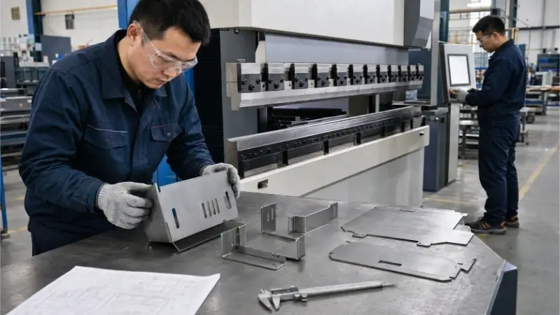
يُعرف «تخفيف الانحناء» في الصفائح المعدنية بأنه شق صغير يُقطع في نهاية خط الانحناء لفصل المادة المنحنية عن السطح المسطح المجاور. وتمنع هذه الفجوة المادية المعدن من التمزق أو الانتفاخ أو التشقق أثناء عملية التشكيل باستخدام مكبس الثني.
على الرغم من بساطتها، تُعد مساحة التخفيف عند الانحناء إحدى الميزات التي غالبًا ما يُساء التعامل معها في تصميم الصفائح المعدنية. فالاعتماد على الإعدادات الافتراضية في SolidWorks أو Fusion 360 غالبًا ما يؤدي إلى مساحات تخفيف ضحلة تتسبب في تمزق الصفائح في ورشة التصنيع، مما يؤدي إلى إتلاف القطع وتأخير الإنتاج.
لسد الفجوة بين النمذجة باستخدام برامج CAD والتصنيع الفعلي، يشرح هذا الدليل بالتفصيل الصيغ الدقيقة لحساب أبعاد مساحات تخفيف الانحناء، والقيود الخاصة بالمواد المختلفة، وقواعد التصميم من أجل التصنيع (DFM) التي تحتاجها لضمان الحصول على زاوية نظيفة وفعالة من حيث التكلفة عند استخدام مكبس الثني.

الأماكن التي تحتاج فعليًّا إلى منحنيات تخفيف الضغط
ثني الصفائح المعدنية يؤدي إلى إجهاد موضعي شديد. إن فهم مكان حدوث هذا الإجهاد وأسباب تسببه في حدوث الضرر يساعد المصممين على تحديد الحالات التي تستلزم استخدام مروحة انحناء، بدلاً من تطبيقها بشكل عشوائي على كل شفة.
تدفق المواد عند نهاية المنعطف
أثناء عملية الثني، يتمدد السطح الخارجي للصفائح المعدنية بينما ينضغط السطح الداخلي. وإذا كانت منطقة الثني تقع مباشرةً بجوار سطح مستوٍ غير مثني، فإن تلك المادة الثابتة تحد من التشوه الطبيعي لمنطقة الثني.
تدفع المادة المضغوطة عند نصف القطر الداخلي إلى الخارج. وفي حالة عدم وجود فصل مادي، يؤدي هذا الإزاحة إلى تمزق حافة الانحناء أو انتفاخها أو إخراج السطح المسطح المجاور عن محاذاة — مما يؤدي غالبًا إلى تحويل قطعة كانت ستكون جاهزة إلى خردة. ويعمل تخفيف الانحناء على عزل منطقة الانحناء، مما يضمن توقف تشوه المادة عند نقطة محددة ومصممة هندسيًا.
الانحناءات الكاملة العرض، والجزئية، والمتقاطعة
تعتمد ضرورة وجود تخفيف الانحناء بشكل كامل على الشكل الهندسي للحافة مقارنةً بالصفائح المعدنية المحيطة بها.
لا يتطلب الانحناء الذي يمتد على كامل عرض جانب القطعة، عمومًا، وجود فتحة تخفيف، نظرًا لعدم وجود مادة مجاورة غير منحنية قد تعيق عملية التشكيل. أما الانحناء الجزئي فيتطلب مساحة تخفيف عند نقطة نهايته لمنع التمزق. ويتطلب الانحناء المحصور — وهو حافة موضوعة داخل الصفيحة — مساحات تخفيف عند كلا الطرفين. وعندما تتقاطع حافتان منفصلتان عند زاوية، يجب على المصممين مراعاة مساحة تخفيف الزاوية بدلاً من مجرد مساحة تخفيف الانحناء الفردي.
| ميزة | الوظيفة الرئيسية | الموقع النموذجي |
|---|---|---|
| تخفيف الانحناء | يخفف الضغط عند نهاية انحناء واحد | الحد الفاصل بين خط منحني ومنطقة مسطحة مجاورة |
| تخفيف الزاوية | يدير التقاطع الذي يتضمن عدة منعطفات | زوايا الصندوق أو العلبة |
| الفجوة الزاوية | يتحكم في الفراغ بين الحواف المشكلة | بين حافتين متجاورتين مشكّلتين |
الثقوب والفتحات بالقرب من المنعطف
عندما مثقوب أو القطع بالليزر عندما تكون العناصر قريبة جدًّا من خط الانحناء، فإنها تدخل في منطقة التشوه النشط. ومع بدء انثناء المادة، تتحول الثقوب الدائرية إلى أشكال بيضاوية، وتشوه الشقوق، وتصبح جذور حواف القطع نقاطًا شائعة لبدء تشكل الشقوق الهيكلية.
في بعض الحالات، قد يعمل الفتحة المجاورة كوسيلة غير متحكم فيها وغير مقصودة لتخفيف الضغط الناتج عن الانحناء، مما يؤدي إلى تشوه السطح المستوي المحيط بها. ورغم أن الفراغ الدقيق يعتمد على درجة صلابة المادة ونصف قطر الانحناء، فإن القاعدة العامة الموثوقة هي الحفاظ على حواف الفتحة على مسافة لا تقل عن 2.5 إلى 3 أضعاف سماكة الصفيحة (2.5t إلى 3t) بعيدًا عن خط الانحناء لمنع تشوه الشكل.
تحديد أبعاد عرض وعمق منحنى التخفيف
غالبًا ما يؤدي الاعتماد حصريًّا على الإعدادات الافتراضية لبرامج التصميم بمساعدة الحاسوب (CAD) إلى حدوث مشكلات تصنيعية أثناء إعدادات الإنتاج. لذا، يجب حساب الأبعاد باستخدام خطوط أساس مرجعية واضحة وحدود تصنيعية عملية.
العرض والعمق ومرجع القياس
لضمان اتساق عملية التصنيع، يجب تحديد الأبعاد بوضوح. عرض التجاويف (W) هو المسافة بين حافتي القطع المتوازيتين. وعمق التجاويف (D) هو طول القطع الممتد داخل القطعة، وهو ما يتطلب نقطة بداية محددة بوضوح — مثل خط الانحناء، أو المماس للانحناء، أو الزاوية الحادة النظرية. يجب أن تحدد الرسومات الهندسية ثنائية الأبعاد بوضوح مرجع القياس المستخدم.
بالنسبة للصفائح المعدنية العامة (مثل الفولاذ الطري، والفولاذ المقاوم للصدأ 304، والألومنيوم 5052)، يمكن للمصممين استخدام هذه الصيغ الأساسية العملية:
- عرض الإغاثة (W): يجب أن يكون مساوياً لسمك المادة (t) أو أكبر منه، مع حد أدنى مطلق يتناسب مع عملية القطع: W ≥ t (الحد الأدنى للعرض: 0.8 مم أو 0.030 بوصة للقطع بالليزر)
- عمق الإغاثة (D): يجب أن يمتد إلى ما بعد خط المماس للانحناء إلى المنطقة المستوية من أجل عزل نصف قطر الانحناء (Ri) بشكل كامل: D ≥ Ri + t + 0.5 مم D ≥ Ri + t + 0.020 بوصة.
وفي النهاية، لا يمكن أن يكون عرض الفتحة المختار أصغر من الحد الأدنى لحجم الميزة التي يمكن للشركة المصنعة معالجتها بشكل موثوق دون حدوث تشوه حراري أو انحشار للأداة.
السماكة، ونصف القطر، وزاوية الانحناء
مع زيادة سماكة الصفيحة (t)، يزداد حجم المادة المزاحّة، مما يتطلب قطعًا أوسع وأعمق بشكل متناسب. وبالمثل، يؤدي نصف قطر الانحناء الداخلي الأكبر (Ri) إلى دفع المماس للانحناء إلى مسافة أبعد داخل النمط المسطح، مما يتطلب عمقًا أكبر (D). كما تؤدي زوايا الانحناء غير المتساوية مع 90 درجة إلى تغيير الموقع الفعلي لمماس الانحناء، مما يغير الخلوص المطلوب للعمق.
من واقع خبرتنا في مراجعة نماذج الإنتاج، فإن أحد الأخطاء الشائعة هو الافتراض بأن نصف القطر الافتراضي في برنامج CAD يتطابق مع نصف القطر الفعلي لآلة ثني الصفائح. ففي الأجزاء المثنية بالهواء، يتحدد نصف القطر الناتج بفتحة القالب السفلي على شكل حرف V، وليس بنموذج CAD. بالنسبة للمواد ذات الاستطالة المنخفضة — مثل الألومنيوم 6061-T6 أو الفولاذ عالي القوة — فإن توسيع فتحة التخفيف وحدها لن يمنع حدوث تشققات إذا كان نصف قطر الانحناء الداخلي ضيقًا جدًّا مقارنةً باتجاه الحبيبات.
النقوش الأصغر من الحجم المعتاد والأكبر من الحجم المعتاد
تؤثر التجاويف ذات الأبعاد غير الصحيحة بشكل مباشر على معدل إنتاجية التصنيع، ومحاذاة التجميع، وتكلفة المعالجة اللاحقة.
| حالة الإغاثة | النتيجة المتوقعة |
|---|---|
| ضيق جدًّا | انتفاخ الزوايا، أو انزياح المواد، أو تراكم الخبث الحراري أثناء القطع |
| ضحل جدًّا | تشقق عند قاعدة الفتحة أو تمزق على طول طرف الانحناء |
| بالمقاس الصحيح | انحناء ثابت، وموضع حافة يمكن التنبؤ به، وفجوة زاوية خاضعة للتحكم |
| واسع جدًا | الفجوة المفرطة بين الزوايا التي تؤثر على المظهر الجمالي والمتانة وملاءمة التجميع |
| عميق جدًا | زيادة الصعوبة في عمليات اللحام والإحكام والطلاء السطحي اللاحقة |
يحدث أحد الأخطاء الشائعة في ورشة العمل عندما يتم حساب عمق تخفيف الانحناء انطلاقًا من خط الانحناء بدلاً من المماس للانحناء. وأثناء أول محاولة للانحناء على مكبس الثني، تتمزق المادة عند قاعدة القطع الضحل، مما يجبر المشغل على إيقاف العملية، وتحديث ملف DXF للنمط المسطح، وإعادة برمجة الآلة — مما يكلف الوقت والمواد على حد سواء.
القيود المتعلقة بالمواد والأدوات والقطع
من الأخطاء الشائعة في تصميم الصفائح المعدنية الافتراض بأن شكل التباعد الواحد في برنامج CAD يناسب جميع المواد وطرق التصنيع. وفي الواقع، يعتمد الحجم والشكل الأمثل للتباعد بشكل كبير على الخصائص الفيزيائية للمعدن والمعدات المستخدمة في معالجته.
حالة المادة واتجاه الحبيبات
تتفاعل السبائك المختلفة مع إجهاد الانحناء بطرق مختلفة تمامًا. ويجب على المصممين تقييم درجة صلابة المادة ومعدل الاستطالة وحساسيتها تجاه الشقوق قبل الانتهاء من تصميم التخفيف.
| مادة | المشكلة الرئيسية المتعلقة بالتخفيف من الانحناء |
|---|---|
| الفولاذ الطري | تتمتع بقدرة تشكيل ممتازة بشكل عام، لكنها لا تزال مقيدة بحدود سماكة الصفائح ونصف القطر الداخلي. |
| 304 الفولاذ المقاوم للصدأ | تتميز بسرعة تصلبها أثناء التشغيل، وارتدادها العالي، وظهور نتوءات صلبة عند جذر التخفيف. |
| ألومنيوم 5052 | تتميز بقدرة جيدة على التشكيل، لكنها تتطلب الانتباه إلى الحواف الحادة واتجاه الألياف لمنع تمزق السطح. |
| الألومنيوم 6061-T6 | شديد الحساسية تجاه نصف القطر الصغير، والشقوق الحادة، واتجاه الحبيبات غير الملائم. عرضة للتشقق المفاجئ. |
بالنسبة للفولاذ عالي القوة والسبائك الهشة مثل 6061-T6، فإن مجرد توسيع فتحة التخفيف لا يُعد حلاً مضمونًا لمنع حدوث التشققات. يجب أن يأخذ التصميم في الاعتبار أيضًا اتجاه الحبيبات (فالثني بشكل عمودي على اتجاه الحبيبات يُعد أكثر أمانًا) وتجنب الزوايا الداخلية الحادة.
بالإضافة إلى ذلك، تتطلب المواد المطلية مسبقًا، مثل الفولاذ المجلفن، عناية خاصة. فالتقطيع التخفيفي يكشف الفولاذ العاري، مما يضعف مقاومة القطعة للتآكل إذا لم يتم إجراء تعديلات تصحيحية بعد العملية. ونظرًا لاختلاف دفعات المواد، لا نوصي بتطبيق عوامل تصحيح ثابتة عامة دون التحقق من صحتها من خلال إجراء اختبارات ثني في ورشة العمل.
نصف قطر الانحناء الفعلي والأدوات المستخدمة
يفترض نموذج CAD وجود نصف قطر نظري مثالي، لكن نصف القطر الفعلي الذي يتشكل في ورشة التصنيع يعتمد على طريقة الثني والأدوات المحددة المستخدمة.
يتم تشكيل معظم الصفائح المعدنية الدقيقة باستخدام تقنية الثني الهوائي. وفي عملية الثني الهوائي، يتحدد نصف القطر الداخلي الفعلي بشكل أساسي من خلال عرض الفتحة السفلية لقالب V، وليس فقط من خلال نصف قطر طرف المثقاب. فإذا حدد المصمم نصف قطر يبلغ 1.0 مم في برنامج CAD، لكن المشغل استخدم قالبًا على شكل حرف V أوسع لتناسب سماكة المادة، فقد يصل نصف القطر الفعلي للانحناء إلى 1.5 مم. ويؤدي هذا النصف القطر الفعلي الأكبر إلى دفع منطقة تشوه الانحناء إلى الخارج. وإذا تم تصميم عمق التخفيف بشكل ضيق وفقًا للقيمة الافتراضية في برنامج CAD، فسيكون غير كافٍ عند استخدام مكبس الثني، مما يؤدي إلى حدوث تمزق.
كما تؤثر قيود أخرى متعلقة بالأدوات على تصميم التضاريس. فقد تتطلب الحواف القصيرة قوالب ضيقة متخصصة، كما أن تسلسلات الثني المعقدة قد تتسبب في حدوث تداخل بين القطعة والأداة.
💡 نصيحة من DFM Pro: لا تثق أبدًا بشكل أعمى في القطر الداخلي الافتراضي لبرنامج CAD الخاص بك. قبل الانتهاء من تحديد مساحات تخفيف الانحناء، اسأل شريكك في التصنيع عن القالب على شكل حرف V الأقل عمقًا الذي سيستخدمه لسمك المادة المحدد الخاص بك. تصميم النمط المسطح الخاص بك من أجل الفعلي يُقضي نصف القطر المُشكَّل على الغالبية العظمى من مشاكل التمزق.
شكل النقش وطريقة القطع
يؤثر شكل القطع البارز على كل من السلامة الهيكلية للقطعة ومدى كفاءة تصنيعها.
| شكل | الميزة الرئيسية | القيد الرئيسي |
|---|---|---|
| مستطيل الشكل | سهلة التصميم باستخدام برامج CAD وفعالة في القطع بالليزر. | تُعد الجذور الحادة بزاوية 90 درجة بمثابة مركّزات للإجهاد. |
| أوبراوند | تقلل الأطراف المستديرة بشكل كبير من تركيز الإجهاد. | يصعب القطع بدقة إذا كان عرض الشق ضيقًا جدًّا. |
| التعميم | يمكن معالجتها بسهولة على مكابس التثقيب التي تعمل بنظام التحكم الرقمي (CNC)؛ وتجنب ظهور حواف حادة. | يحتل مساحة أكبر؛ ويترك فجوة أكبر وأكثر وضوحًا بعد التشكيل. |
تحدد طريقة القطع المختارة للنمط المسطح بشكل صارم الحد الأدنى لعرض النتوء:
- القطع بالليزر: يعتمد ذلك على عرض الشق، ومدخلات الحرارة، وتصريف الخبث. فإذا تم تشكيل شق ضيق جدًّا، فقد يؤدي الليزر إلى صهر المادة المحيطة بدلاً من قطع فجوة نظيفة.
- التثقيب باستخدام الحاسب الآلي الرقمي: يقتصر ذلك على الحد الأدنى لحجم أداة التثقيب وقوتها. فمثقاب مستطيل بعرض 1 مم سينكسر إذا استُخدم على فولاذ مقاوم للصدأ بسمك 3 مم.
- التشكيل بالقطع باستخدام الحاسب الآلي (التصنيع): يُستخدم عادةً مع الألواح الألومنيوم. يجب أن يتناسب القطع البارز مع نصف قطر رأس المثقاب.
- القطع بالماء: قد تظهر الشقوق الضيقة انحناءً مرئيًّا في الحواف.
💡 ملاحظة من الخبراء بشأن تحذيرات CAD: توفر العديد من برامج التصميم بمساعدة الحاسوب (CAD) (مثل SolidWorks أو Fusion 360) خيار “Tear” لتخفيف الانحناء، والذي ينتج عنه قطع بعرض صفر. لا تستخدم هذا مع القطع المقطوعة بالليزر. يتميز الليزر بعرض شعاع فيزيائي (شق)؛ فخط العرض الصفري إما أن يتجاهله برنامج الترتيب، أو يتسبب في توقف الليزر لفترة قصيرة مما يؤدي إلى صهر الزاوية، مما ينتج عنه خبث صلب يفسد عملية الثني.

الزاوية النهائية: الملاءمة واللحام والطلاء
لا يؤثر تصميم شكل الانحناء فقط على تشغيل مكبس الثني؛ بل إنه يحدد جودة وتكلفة العمليات اللاحقة، بما في ذلك التجميع واللحام والتشطيب السطحي.
فجوة الزاوية وتركيب الحافة
عندما تلتقي حافتان عند زاوية، فإن انحناء التخفيف هو الذي يحدد الفجوة النهائية في الزاوية ومحاذاة الحافتين.
يوفر التوسع الأوسع في منطقة الانحناء لمشغل مكبس الثني هامشًا أكبر للتسامح مع حالات الاختلال الطفيف في محاذاة الأدوات، مما يضمن ثني الحواف بشكل مستقيم. ومع ذلك، فإن التوسعات المفرطة في هذه المنطقة تؤدي إلى تفاقم المشكلة في مراحل لاحقة من عملية التصنيع. فالراحة الكبيرة تترك فجوة زاوية مفتوحة ملحوظة تقلل من المظهر الجمالي للقطعة، وتضعف الصلابة الهيكلية، وتعقّد عملية تجميع المكونات المقترنة.
اللحام والختم
بالنسبة للأجزاء التي تتطلب زوايا ملحومة أو عزلًا بيئيًّا مطابقًا لمعايير IP، فإن الفجوة الزاوية الناتجة عن انحناء التخفيف تصبح عاملاً حاسماً في تحديد التكلفة.
- اللحام بتقنيتي TIG و MIG: يجب أن تكون الفجوة مستقرة وقابلة للملء. فإذا تركت الشق التخفيفي فتحة أكبر من اللازم، يتعين على عامل اللحام استخدام كمية أكبر بكثير من سلك الحشو. وهذا يؤدي إلى زيادة مدخلات الحرارة، مما يؤدي حتمًا إلى تشوه حراري شديد (انحراف) في جميع أنحاء القطعة.
- اللحام بالليزر: حساس للغاية تجاه ملاءمة الأجزاء. يتطلب اللحام بالليزر عادةً فجوات تقترب من الصفر، ولا يمكنه بسهولة سد التجاويف الزاوية الواسعة وغير الدقيقة.
- تطبيقات الختم: لا يمكن للعلب التي تتطلب إحكامًا مانعًا لتسرب الماء أن تعتمد على التلامس الطبيعي بين المعدن والمعدن في حالتي الحافتين المثنيتين. ويجب أن تتيح منطقة التفريغ مسارًا متواصلًا لمادة الإحكام السائلة أو الحشيات.
- التصميم الصحي: يجب أن تتجنب المعدات المخصصة للأغذية والمعدات الطبية وجود المناطق التي قد تتجمع فيها الأوساخ. فالأشكال البارزة الكبيرة الحجم أو المعقدة تخلق مساحات ميتة تؤوي البكتيريا ويصعب تنظيفها.
ورغم أن النتوء شبه البيضاوي يساعد في تقليل الضغط عند الجذر، إلا أنه لا يجعل الزاوية مناسبة تلقائيًا للختم. يجب تقييم الشكل الهندسي النهائي بناءً على الحالة بعد التشكيل، وليس فقط بناءً على النموذج المسطح.
إزالة الحواف الخشنة وتشطيب الأسطح
غالبًا ما تكشف عمليات المعالجة اللاحقة عن عيوب خفية في تصاميم التخفيف في الانحناءات الضيقة.
غالبًا ما تبدأ الشقوق الدقيقة عند قاعدة النقش البارز إذا تركت عملية القطع وراءها نتوءات أو بقايا الليزر. ويُعد إزالة النتوءات بشكل سليم أمرًا ضروريًا لمنع المخاطر التي قد تهدد سلامة المستخدمين النهائيين. ومع ذلك، فإن إزالة الحواف الخشنة يدويًّا من الشقوق التخفيفية الضيقة وسوء التصميم هي عملية تتطلب جهدًا كبيرًا، مما سيؤدي مباشرةً إلى ارتفاع سعر الوحدة للقطعة الخاصة بك.
تؤثر عمليات تشطيب الأسطح، مثل الطلاء بالمسحوق أو الطلاء الكهربائي، بشكل مباشر على أبعاد النقش البارز. فإذا تم رسم فتحة نقش بارز بعرض أدنى مطلق (على سبيل المثال، 0.5 مم)، فإن الطلاء بالمسحوق غالبًا ما يتسبب في “التواصل”—حيث يتجمع الطلاء ويتصلب عبر الفجوة، مكونًا شبكة قبيحة قد تعيق تلامس الأجزاء. وعلى العكس من ذلك، فإن تأثير قفص فاراداي يجعل من الصعب على المسحوق أن يلتصق بشكل صحيح داخل الزوايا العميقة والضيقة والحادة، مما يترك المعدن مكشوفًا.
💡 نصيحة من DFM Pro: لا تعتمد على تعويضات الفجوات العامة الخاصة بالطلاء. ناقش سماكة الطلاء ومخاطر تكوّن الجسور مع شريكك في التصنيع قبل تحديد الفجوات الزاوية بشكل نهائي، خاصةً في العلب الثقيلة المطلية بالمسحوق.
من النموذج الحاسوبي (CAD) إلى الإنتاج المعتمد
لا فائدة من جزء ثلاثي الأبعاد مصمم بشكل مثالي إذا كان الرسم ثنائي الأبعاد يفتقر إلى المعلومات الحاسمة المتعلقة بالمعالجة. ويتطلب الانتقال من نظام التصميم بمساعدة الحاسوب (CAD) إلى مرحلة الإنتاج تحديدًا واضحًا لكيفية قياس وتشكيل وفحص مساحة التخفيف عند الثني.
إعدادات CAD والتوضيحات المرفقة بالرسومات
تعد المعلمات الافتراضية للصفائح المعدنية في برامج مثل SolidWorks أو Fusion 360 أو Creo مجرد وسائل تسهيلية للنمذجة؛ فهي لا تمثل القدرات الفعلية للمصنع في مجال الأدوات أو القطع.
لضمان أن يكون المنتج النهائي مطابقًا للنموذج الذي صممته، يجب أن يتضمن الرسم التصنيعي الخاص بك ما يلي بشكل صريح:
- درجة المادة ودرجة الصلابة (على سبيل المثال، 5052-H32 مقابل 6061-T6)
- سُمك الورقة
- اتجاه الانحناء وزاويته
- نصف قطر الانحناء الداخلي المستهدف
- أبعاد عرض وعمق النقوش البارزة
- مرجع القياس: حدد بوضوح ما إذا كان العمق يُقاس من خط الانحناء، أم من المماس للانحناء، أم من زاوية حادة افتراضية.
- قيود اتجاه الألياف (إذا كانت ذات أهمية حاسمة لسلامة الهيكل)
- التفاوتات المسموح بها في فجوة الزوايا بعد التشكيل
- متطلبات المعالجة اللاحقة (اللحام، أو الختم، أو الطلاء)
💡 نصيحة من DFM Pro: لا تعتمد على ميزة “القطع” ذات العرض الصفري في برنامج التصميم بمساعدة الحاسوب (CAD) الخاص بك، ما لم يؤكد شريكك في التصنيع بشكل محدد كيفية إنتاج هذه الميزة. ففي الواقع، تترك آلات القطع بالليزر شقاً، وغالباً ما تؤدي محاولة إجراء قطع بعرض صفري إلى تكوّن خبث صلب وتشوه الحواف.
فحص النموذج الأولي وفحص المنتج الأول (FAI)
لا يقتصر فحص القطعة الأولى (FAI) للأجزاء المثنية على قياس الشكل المسطح فحسب. بل إن الفحص السليم للقطعة الأولى يقيّم السلوك الفيزيائي للمعدن بعد تعرضه للتشوه.
يجب على مهندسي مراقبة الجودة فحص ما يلي:
- عرض وعمق الفتحة في الحالة المسطحة غير المثنية
- الحل الأمثل للتخلص من الشقوق الدقيقة أو النتوءات المتصلبة
- نهاية الانحناء الذي يؤدي إلى انتفاخ المادة أو تمزقها
- الزوايا والأطوال النهائية للشفة
- تشوه أي ثقوب أو فتحات تقع بالقرب من منطقة الانحناء
- البعد النهائي لفجوة الزاوية في الحالة المشكلة
- تحضير قطع الأجزاء قبل اللحام
- حالة فتحة التهوية بعد الطلاء بالمسحوق أو الطلاء الكهربائي
بالنسبة للأجزاء المصنوعة من مواد صلبة (مثل 6061-T6)، والتي تتميز بحواف قصيرة أو زوايا مغلقة أو تتطلب إحكامًا مطابقًا لمعايير IP، نوصي بشدة بإجراء اختبار ثني قبل الموافقة على الإنتاج بكميات كبيرة.
العيوب الشائعة وتأثيرها على التكلفة ومدة التنفيذ
لا تقتصر عيوب التصميم في أجزاء التخفيف عند الانحناء على إحداث مشاكل شكلية فحسب؛ بل إنها تؤدي بشكل مباشر إلى ارتفاع سعر الوحدة من خلال زيادة معدلات الخردة، وإعادة العمل، والأهم من ذلك، تأخيرات الإنتاج.
| المشكلة | السبب المحتمل | التأثير على الإنتاج |
|---|---|---|
| تشققات أطراف الانحناء | التخفيف ضحل جدًّا، أو نصف القطر الداخلي ضيق جدًّا، أو درجة صلابة المادة غير مناسبة. | إما التخلص من القطعة بالكامل أو إعادة العمل عليها باللحام اليدوي المكلفة،, مما يؤدي غالبًا إلى تأخير الشحن لعدة أيام. |
| انتفاخ الزاوية | التخفيف ضيق جدًّا أو غير موضوع في الموضع الصحيح بالنسبة لمماس المنعطف. | زيادة الوقت المستغرق في عمليات التسوية اليدوية والفحص،, تأجيل جداول التجميع. |
| عدم محاذاة الشفة | تصميم النقش غير المتماثل أو تغيير أدوات آلة الثني. | تداخل الهيكل مع المكونات المقترنة،, مما يؤدي إلى حالات الرفض عبر الحدود. |
| فجوة زاوية مفرطة | تم تصميم النقش بحيث يكون عريضًا جدًّا أو عميقًا جدًّا. | الزيادة الكبيرة في وقت اللحام، ومواد الحشو، وتكاليف الإحكام،, مما يؤدي إلى تجاوزات في الميزانية. |
| قطع الشقوق غير المستقر | عرض الفتحة أقل من الحد الأقصى المستقر للمعالجة بالليزر أو المثقاب. | تباطؤ أداء الآلات، أو التغييرات المطلوبة في العمليات، أو تنظيف الحواف،, مما يؤثر على المدة الإجمالية للتنفيذ. |
| تراكم الطلاء (التجسير) | الفجوة التمهيدية صغيرة جدًّا بحيث لا تكفي لاستيعاب سماكة الطلاء المسحوق. | تداخل في التجميع وتشطيب خارجي رديء، مما يستلزم إعادة العمل باستخدام مواد كاشطة. |
قائمة مراجعة طلبات عروض الأسعار الخاصة بالصفائح المعدنية
للحصول على عرض أسعار دقيق وسريع دون الحاجة إلى تعديلات هندسية لا نهاية لها، تأكد من أن ملف طلب عرض الأسعار الخاص بك يتضمن ما يلي:
- رسومات PDF ثنائية الأبعاد (مع التفاوتات المسموح بها الحرجة) ونماذج ثلاثية الأبعاد أصلية/بصيغة STEP
- درجة المواد المحددة ودرجة الصلابة
- المتطلبات الدقيقة لسمك الصفائح وتشطيب السطح
- نصف قطر الانحناء الداخلي المستهدف
- متطلبات محددة تتعلق بالزوايا (مثل: “يجب لحامها لإغلاقها” أو “تركها مفتوحة للتصريف”)
- الكميات المطلوبة لكل من مرحلة تصنيع النماذج الأولية والإنتاج الضخم
خاتمة
يجب تصميم أبعاد تخفيف الانحناء استنادًا إلى الشكل الهندسي الفعلي للانحناء، وليس بناءً على صيغة عامة واحدة. ويجب على المصممين مراعاة سماكة الصفيحة، ونصف القطر الداخلي الفعلي، ودرجة صلابة المادة، وأدوات مكبس الثني المتاحة، وقيود القطع، والمتطلبات الوظيفية للزاوية النهائية قبل الموافقة على بدء إنتاج القطعة. إن الاهتمام بهذا التفصيل الصغير يؤدي إلى التخلص من الخردة، ويقلل من إعادة العمل اليدوي، ويضمن انتقالاً سلساً من النموذج الأولي إلى التصنيع بالجملة.
هل أنت مستعد للانتقال إلى مرحلة الإنتاج دون الحاجة إلى التخمين؟
لا تدع خطأً بسيطًا في عملية إزالة الانحناء يؤخر مشروعك. أرسل رسوماتك ثنائية الأبعاد ونماذجك ثلاثية الأبعاد إلى شينغن. سيقوم فريقنا الهندسي بإجراء مراجعة مجانية وشاملة لتصميم قابلية التصنيع (DFM) — تتضمن فحص مساحات التخفيف عند الانحناء، وإمكانية وصول الأدوات، وحالة الزوايا — قبل البدء في قطع أي معدن.
مهلا، أنا كيفن لي
على مدى السنوات العشر الماضية، كنت منغمسًا في أشكال مختلفة من تصنيع الصفائح المعدنية، وشاركت رؤى رائعة هنا من تجاربي عبر ورش العمل المتنوعة.
ابقى على تواصل
كيفن لي
لدي أكثر من عشر سنوات من الخبرة المهنية في تصنيع الصفائح المعدنية، وتخصصت في القطع بالليزر، والثني، واللحام، وتقنيات معالجة الأسطح. كمدير فني في شنغن، أنا ملتزم بحل تحديات التصنيع المعقدة ودفع الابتكار والجودة في كل مشروع.
الموارد ذات الصلة