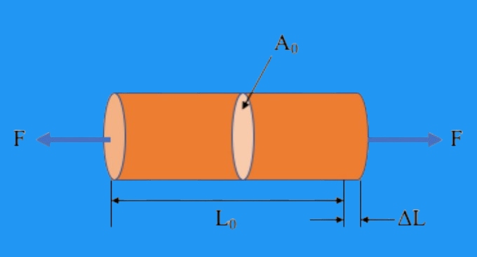
引張試験材料科学の礎石
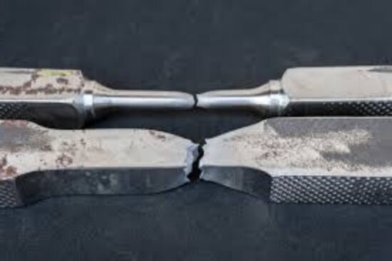
引張試験は、材料特性を測定する最も一般的な方法のひとつです。エンジニアがサンプルが破断するまで引っ張ることで、強度、延性、靭性に関する詳細な情報が得られます。この試験は、研究、品質管理、製品設計に広く利用されています。
応力-ひずみ曲線の理解
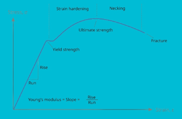
引張試験の主な結果は応力-ひずみ曲線です。応力-ひずみ曲線は、力が増加するにつれて材料がどのように伸びるかを示しています。最初、曲線は直線状に上昇します。この直線部分は弾性変形を表し、力を取り除くと材料は元の形状に戻ります。
荷重が増加すると、曲線は塑性域に曲がり、永久変形が始まる。曲線が直線から離れる点が降伏強さを示す。曲線は極限引張強さ(UTS)のピークに達するまで上昇します。この後、材料は弱くなり、最終的には破断する。
この曲線は、エンジニアに張力下での材料の挙動を視覚化したマップを与える。各段階は、安全な作業条件から故障までの性能を示しています。
引張試験の主要パラメータ
引張試験からはいくつかの重要な値が得られる:
- 降伏強度 - 永久変形が始まる応力。材料が安全な範囲内にあることを保証する。
- 極限引張強さ(UTS) - 材料が破損するまでに扱える最大応力。材料が耐えられる最大荷重を決定するのに役立つ。
- 破断伸度 - 材料が破断する前にどれだけ伸びるか。これは延性を示す。伸びの大きい材料は、破壊に至るまでに多くのエネルギーを吸収することができる。
- ヤング率 - 曲線の弾性部分の傾きから計算される剛性を表す。弾性率が高いほど硬く、低いほど柔軟である。
引張強さに影響する因子
引張強さはどのような状況でも同じではありません。引張強さは、材料が本来持っている性質と、その材料が直面する条件によって異なります。これらの要素を理解することは、エンジニアが性能を予測し、それぞれの用途に適した材料を選択するのに役立ちます。
材料特性と組成
材料の原子構造は引張強さに強く影響する。鋼鉄のように、結晶が密に詰まった金属は、アルミニウムのような柔らかい金属よりも引っ張る力に強く抵抗する。合金化も重要である。クロムやニッケルなどの元素を加えることで、鋼の結晶粒構造が変化し、強度が増します。
不純物や内部欠陥は引張強度を低下させる。小さな亀裂、空隙、非金属介在物が弱点となる。結晶粒の大きさも重要である。結晶粒が小さいと、塑性変形の原因となる転位の動きが妨げられ、材料が強化されることが多い。
その他の固有要素には、密度、結合タイプ、微細構造などがある。これらは、外部処理を行う前に、材料の基本性能を設定する。
外部条件と処理
外的要因は引張強さを大きく変化させる。温度は大きな影響を与える。金属は通常、高温になると弱くなり、延性が増す。低温では、強くなるがもろくなる。
加工方法も強度に影響する。 熱処理焼き入れや焼き戻しなどの機械加工は、硬度と靭性のバランスをとることで鋼を改良することができる。機械加工は ローリング または 鍛造結晶粒を整列させて引張強度を高めることができる。
しかし、加工不良や 溶接 は残留応力を生み出し、パフォーマンスを低下させる可能性がある。環境要因も重要である。腐食、湿度、化学薬品への暴露は、時間の経過とともに引張強度を低下させます。この影響を遅らせるために、保護コーティングや保護処理が施されることが多い。
工学設計と解析における引張応力
エンジニアは、ほとんどすべての設計において引張応力を考慮しなければなりません。小さな部品であれ、大きな構造物であれ、引っ張り力に対応できるかどうかが、性能、耐久性、安全性に影響します。
引張荷重に対する設計の原則
引張荷重に対する設計は、材料の降伏強度と極限引張強度を知ることから始まります。エンジニアは、安全な弾性範囲内にとどまりながら、予想される力に対応できる材料を選択します。部品の断面積も重要です。面積が大きければ応力は減少し、小さければ応力は増加します。
応力の集中は管理されなければならない。鋭利な角、穴、切り欠きなどは、応力が集中する弱点となる。丸みを帯びたエッジ、フィレット、補強材は、応力を均等に分散させ、亀裂の発生や拡大を防ぎます。
設計者は疲労も考慮する。部品が引張強度を下回っていても、繰り返し荷重と除荷が加わると徐々に破損することがあります。疲労に強い材料や形状を選ぶことで、部品の寿命を延ばすことができます。
安全要因の役割
どんな計算も完璧ではありません。荷重が予想より大きくなったり、材料に欠陥があったり、条件が変わったりすることもある。エンジニアは、これらの不確実性に対処するために安全係数を使用します。
安全係数とは、予想される使用応力と材料が扱える最大応力との間の余裕のことである。例えば、引張強度が400MPaで設計荷重が100MPaの材料は、安全係数4となります。これは、その部品が予想される荷重の4倍の強度を持つように設計されていることを意味します。
安全係数の大きさは用途によって異なる。低リスクの部品には小さな係数が必要かもしれませんが、橋梁や航空機のような重要な構造物にははるかに高い係数が必要です。これにより、予期せぬ過酷な条件下でも性能を確保することができます。