Mecanizar piezas complejas nunca es tarea fácil. Ingenieros y fabricantes trabajan a diario con tolerancias muy ajustadas, formas intrincadas y materiales muy exigentes. Muchos proyectos fracasan no porque el diseño sea defectuoso, sino porque pequeños detalles -como la colocación de los orificios, el acceso a las herramientas o la sujeción de las piezas- se pasan por alto al principio del proceso.
Este artículo se ha escrito para ayudar a cerrar esa brecha. Su objetivo es compartir ideas claras y valiosas que simplifiquen, aceleren y mejoren la fiabilidad del mecanizado de piezas complejas. Mediante el examen de los retos más comunes y la aportación de consejos prácticos, pretendemos ayudar a ingenieros, diseñadores y equipos de producción a reducir el número de pruebas y errores y, en última instancia, lograr resultados más estables.
Ahora, repasemos cada área paso a paso y veamos cómo un diseño innovador y una planificación cuidadosa pueden convertir piezas complejas en proyectos de mecanizado fluidos y satisfactorios.
1. Planifique cuidadosamente la colocación de los orificios
Al diseñar las piezas, tenga en cuenta el espaciado y la profundidad al principio del proceso. Mantenga los orificios alejados de bordes, paredes finas y esquinas para evitar distorsiones. Los agujeros demasiado juntos pueden eliminar demasiado material a la vez, generando calor y reduciendo la precisión dimensional.
Agrupar los orificios por tamaño y profundidad puede agilizar el proceso de producción. Reduce los cambios de herramienta y mantiene unas condiciones de mecanizado uniformes. Para agujeros profundos, lo más eficaz es el taladrado escalonado: empezar con un agujero piloto más pequeño e ir agrandándolo gradualmente. Así se mantiene la estabilidad de la herramienta y se garantiza una mejor evacuación de la viruta.
Como referencia, los orificios en el eje suelen tener un diámetro de 1 mm. En cambio, los orificios laterales o radiales deben ser ligeramente mayores, en torno a 2 mm, para mantener la resistencia y evitar la desviación de la herramienta. Los agujeros profundos no suelen superar seis veces el diámetro del agujero para evitar la inestabilidad.
Alinee los orificios a lo largo de ejes comunes siempre que sea posible. Esto permite a la máquina realizar varios orificios en una sola configuración, lo que mejora la precisión y reduce el tiempo de ciclo. Si es necesario realizar orificios en ángulo o descentrados, simule las trayectorias de la herramienta en 3D para comprobar si hay problemas de holgura y evitar colisiones.
2. Gestionar funciones profundas con estrategia
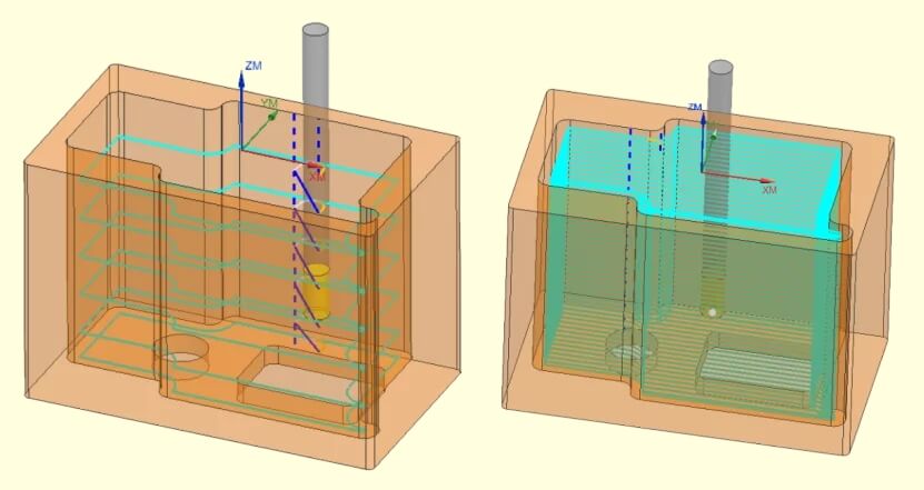
Los elementos profundos, como cajeras, ranuras y cavidades, son habituales en piezas complejas, pero requieren una planificación cuidadosa para mecanizarlos con precisión. Sin un enfoque adecuado, las herramientas largas pueden doblarse o vibrar, lo que afecta tanto a la precisión como a la calidad de la superficie. Las fuerzas desiguales durante el corte profundo también pueden crear tensiones internas que provoquen alabeos o deformaciones tras el mecanizado.
Utilice la herramienta más corta que pueda alcanzar la profundidad requerida. Una herramienta más corta tiene mayor rigidez y produce una superficie más lisa. Cuando sea necesario realizar rasgos profundos, elimine el material en varias pasadas descendentes en lugar de cortar toda la profundidad de una sola vez. Esto mantiene las fuerzas de corte estables y mejora la vida útil de la herramienta.
Como referencia de diseño, intente que la profundidad de una ranura o cajera fresada no supere seis veces su anchura. Sobrepasar esta proporción suele aumentar el riesgo de vibración y desviación de la herramienta. Deje al menos 0,5 mm (0,020 pulg.) de grosor de pared junto al elemento para mantener la resistencia y evitar distorsiones. Para ranuras externas en piezas torneadas, mantenga la profundidad por debajo de 24,1 mm (0,95 pulg.) y evite anchuras inferiores a 1,2 mm (0,047 pulg.). Seguir estos límites fundamentales ayuda a encontrar un equilibrio entre precisión y estabilidad.
3. Diseñar mejores roscas e insertos
Comience con el tamaño de rosca y la clase de ajuste correctos para su pieza. En el caso de roscas internas, asegúrese de que la pared circundante es lo suficientemente gruesa como para evitar grietas o deformaciones durante el proceso de corte. Evite colocar los orificios roscados demasiado cerca de bordes o secciones delgadas, ya que esto puede debilitar la pieza y causar problemas de montaje.
Elija los métodos de creación de roscas en función del material. Los metales duros suelen funcionar mejor con el fresado de roscas, que produce roscas limpias y permite pequeños ajustes sin necesidad de cambiar de herramienta. Los metales más blandos, como el aluminio, pueden roscarse con eficacia, pero se necesita una buena lubricación y un buen control de la viruta para evitar desgarros o gripado.
Supongamos que la pieza tiene varias características roscadas; agrupe las roscas del mismo tamaño y tipo. Esto reduce la necesidad de cambiar de herramienta y acorta la duración del ciclo. Utilizar tamaños de rosca estándar siempre que sea posible también ayuda. Las roscas personalizadas pueden ralentizar la producción, dificultar el mantenimiento y aumentar el riesgo de errores.
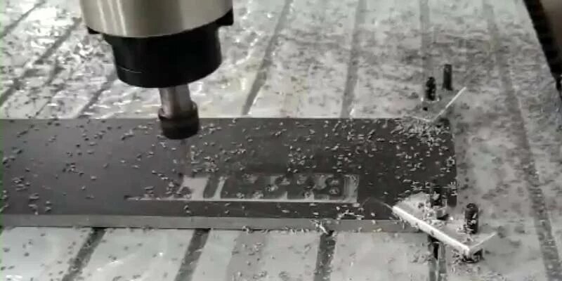
4. Texto sencillo y práctico
Añadir texto, logotipos o etiquetas a las piezas mecanizadas es habitual, pero puede ralentizar la producción y aumentar los costes si no se diseña con cuidado. Fuentes muy detalladas, grabados profundoso caracteres diminutos pueden desgastar las herramientas con mayor rapidez, prolongar los tiempos de ciclo y, en ocasiones, dificultar la lectura de las marcas. El texto sencillo es más fácil de mecanizar, produce resultados más limpios y evita complicaciones innecesarias.
Elija fuentes claras y fáciles de cortar. Las fuentes sin gracias con trazos uniformes, como Arial o Helvetica, son las más adecuadas para el mecanizado CNC. Evite las fuentes decorativas o cursivas, ya que sus curvas finas y detalles finos son difíciles de reproducir con precisión por las máquinas. Utilice caracteres de mayor tamaño siempre que sea posible, sobre todo en piezas pequeñas en las que el acceso a las herramientas sea limitado.
Controle cuidadosamente la profundidad del grabado. Un texto poco profundo, de unos 0,2-0,5 mm de profundidad, suele ser suficiente para una buena visibilidad. Los grabados profundos requieren más pasadas y aumentan el riesgo de rotura de la herramienta. Si el texto está destinado a la identificación más que a la función, el grabado superficial es más rápido, limpio y consistente que el corte profundo.
5. Añadir radios adecuados a las esquinas
Diseñe las esquinas internas con radios que igualen o superen ligeramente el radio de la fresa. Por ejemplo, si utiliza una fresa de 6 mm, ajuste el radio de la esquina a 3 mm como mínimo o un poco más. Esto permite que la herramienta se mueva suavemente sin dejar material sin cortar ni causar tensiones excesivas. Los radios más grandes también le permitirán trabajar con mayores velocidades de avance y reducir el desgaste de la herramienta.
Evite radios muy pequeños o incoherentes en elementos similares. Cada tamaño diferente puede aumentar el tiempo de programación y requerir herramientas distintas. Utilizar radios uniformes siempre que sea posible simplifica la configuración y mejora la repetibilidad. Si las esquinas afiladas son esenciales, considere un proceso secundario como Mecanizado por descarga eléctrica (EDM)que puede producir bordes precisos, pero añade tiempo y costes.
Los radios también mejoran la resistencia de las piezas. Las esquinas afiladas actúan como puntos de tensión donde pueden empezar las grietas, especialmente en piezas de carga. Si se añade un radio, aunque sea pequeño, la tensión se reparte de forma más uniforme, lo que aumenta la durabilidad y reduce el riesgo de fallo por fatiga con el paso del tiempo.
6. Piense de antemano en el acceso a las herramientas
Antes de mecanizar, visualice cómo llegará la herramienta de corte a cada elemento para garantizar una operación sin problemas. Cada cara, cavidad y orificio debe tener un camino despejado sin obstrucciones. Los elementos profundos u ocultos pueden requerir ligeros ajustes de diseño, como ensanchar un ángulo o desplazar un elemento, para que las herramientas estándar se adapten y funcionen con eficacia.
Evite los diseños que obliguen a la herramienta a trabajar en ángulos pronunciados o en espacios reducidos durante períodos prolongados. Estas condiciones aumentan la vibración y la desviación de la herramienta, lo que puede afectar a la precisión y al acabado superficial. En su lugar, divida los elementos complejos en varias pasadas menos profundas que las herramientas más cortas y rígidas puedan manejar con facilidad.
En el caso de las máquinas CNC multieje, aproveche su capacidad para reposicionar la pieza automáticamente. Esto mejora el acceso desde múltiples ángulos y puede reducir el número de configuraciones necesarias. Incluso con Mecanizado en 5 ejesLas esquinas internas afiladas o las superficies bloqueadas pueden limitar el movimiento de la herramienta, por lo que mantener los diseños lisos y abiertos ayuda a mantener la eficacia y la precisión.
7. Optimizar la fijación para la estabilidad
Considere cómo se sujetará la pieza antes de iniciar el mecanizado. Cada pieza requiere un punto de referencia estable, o punto de referencia, para garantizar un posicionamiento y una alineación coherentes. Las piezas complejas pueden requerir múltiples configuraciones, por lo que se deben incluir superficies planas y accesibles que puedan sujetarse con seguridad sin bloquear la herramienta. Evite utilizar zonas curvas o delgadas para la fijación, ya que pueden doblarse o deformarse bajo presión.
Distribuya uniformemente las fuerzas de apriete. Una presión desigual puede deformar la pieza, especialmente en secciones de paredes finas. Las mordazas blandas, las fijaciones a medida o las mesas de vacío son útiles para materiales delicados. Las fijaciones modulares funcionan bien para prototipos o lotes pequeños porque pueden ajustarse rápidamente entre piezas.
Para el mecanizado multieje, planifique fijaciones que permitan el acceso a todos los elementos críticos. Una fijación bien diseñada reduce el número de reposicionamientos, disminuye los errores de alineación y acorta los tiempos de ciclo.
Mejore la eficacia de su mecanizado y minimice los costosos errores con la asistencia de expertos en CNC. Póngase en contacto con nosotros para hablar de su complejo proyecto y recibir un presupuesto rápido y sin compromiso.
Hola, soy Kevin Lee

Durante los últimos 10 años, he estado inmerso en diversas formas de fabricación de chapa metálica, compartiendo aquí ideas interesantes de mis experiencias en diversos talleres.
Póngase en contacto
Kevin Lee
Tengo más de diez años de experiencia profesional en la fabricación de chapas metálicas, especializada en corte por láser, plegado, soldadura y técnicas de tratamiento de superficies. Como Director Técnico de Shengen, me comprometo a resolver complejos retos de fabricación y a impulsar la innovación y la calidad en cada proyecto.
Recursos relacionados


Mecanizado de filetes: Qué determina el coste y la calidad de las piezas

Acero inoxidable antihuellas: cómo funciona y cómo elegirlo
