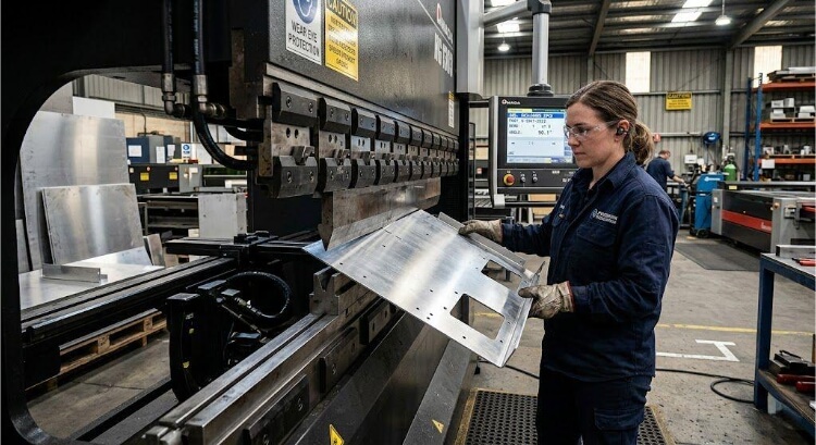
In modern manufacturing, aluminum is prized for its high strength-to-weight ratio. However, for a fabricator, it is a “temperamental” metal. Unlike mild steel, which is relatively forgiving, aluminum has a unique crystalline structure that makes it prone to orange peeling, galling, and catastrophic fractures if approached incorrectly.
To achieve a perfect bend, you must balance three technical variables: the alloy’s temper, the internal bend radius, and the grain direction. This guide provides the practical data and physical logic required to eliminate scrap, reduce production costs, and ensure structural integrity.
Understanding Aluminum Alloys and Their Bendability
In aluminum bending fabrication, the alloy series defines the chemistry, but the temper (the hardness state) dictates whether the part will survive the press brake.
5052 vs. 6061: Balancing Strength and Formability
- 5052-H32 (The Industry Standard): This magnesium-alloyed aluminum is the gold standard for sheet metal bending. The H32 temper (strain-hardened and stabilized) provides excellent ductility. It rarely cracks under standard radii and is ideal for complex electronics enclosures and brackets.
- 6061-T6 (The Structural Challenge): 6061 is highly sought after for its structural strength, but in its T6 state, it is brittle. Attempting a tight-radius bend on 6061-T6 often leads to immediate fracture. It requires a radius 3 to 6 times its thickness or specialized heat treatment.
Engineering Trade-offs
- -O (Annealed): The softest state, easiest to bend, but lacks structural rigidity.
- -T4 vs. -T6: If your design requires high strength but the T6 temper is causing high scrap rates, consider specifying 6061-T4. It is significantly more formable than T6 and will naturally age-harden over time, or can be artificially aged to T6 after bending to restore full strength.
Pro Tip: Understanding the Mill Test Report (MTR) is vital for procurement. Aluminum naturally age-hardens; material that has been sitting in a warehouse for months will exhibit higher yield strength and more unpredictable springback than fresh stock.
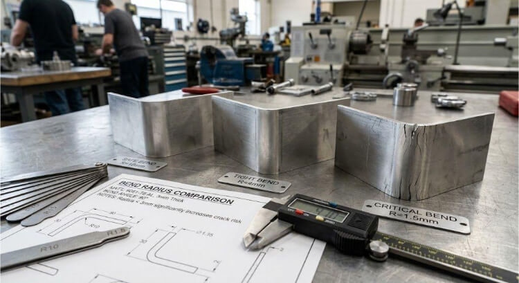
Minimum Bend Radius: The Physics of Failure Prevention
The most common mistake in aluminum design is specifying an internal radius that is too sharp. When aluminum is bent, the outer surface is placed under extreme tension. If the radius is too small, the metal grains separate, leading to structural failure.
“Orange Peel” vs. Structural Cracks
Before aluminum snaps, the surface often develops a textured, rough appearance known as Orange Peel.
- The Quality Standard: While “crazing” (light surface texturing) is common in harder alloys, it becomes a failure if a fingernail can catch in the crack. In aerospace or medical applications, orange peeling is a rejected defect because it creates stress concentrators where fatigue cracks will initiate under operational vibration.
Technical Reference: Minimum Internal Radius (r) Guide
To ensure a successful bend without micro-fracturing, use this R/t (Radius to Thickness) ratio:
| Material Thickness (t) | 5052-H32 Min Radius | 6061-T6 Min Radius |
|---|---|---|
| 1.0 mm | 1.0 mm | 3.0 mm |
| 2.0 mm | 2.5 mm | 6.0 mm |
| 3.0 mm | 4.0 mm | 10.0 mm |
| 6.0 mm | 9.0 mm | 25.0 mm |
The Physics of “Sharp” Bends
Never design a “sharp” internal corner for aluminum. A sharp punch acts like a wedge, initiating a micro-tear at the apex of the bend. Always specify the largest radius your assembly allows. A larger radius not only improves structural integrity but also makes springback more predictable, leading to higher dimensional consistency and lower setup costs.
The Role of Grain Direction in Aluminum Bending
In sheet metal fabrication, aluminum is not an isotropic material (meaning it does not behave the same way in all directions). During the mill-rolling process, the metal is subjected to immense pressure, which elongates its internal crystalline structure along the direction of the roll. Ignoring this “grain direction” during the CAD nesting phase is a primary cause of unpredictable cracking.
The Physics of Grain Boundaries
Think of aluminum’s grain structure like the grain in a piece of wood.
- Bending With the Grain (Longitudinal): If you align your bend line parallel to the rolling direction, you are bending along the boundaries of these elongated crystals. The tensile stress forces the grains apart, acting almost like a perforated tear-line. This drastically increases the likelihood of severe orange peeling or a complete fracture, especially in harder tempers.
- Bending Across the Grain (Transverse): By orienting the bend line perpendicular to the grain, the bending stress is distributed across the long fibers of the metal rather than between them. This is the strongest possible orientation and allows for tighter radii without compromising the part.
The 45-Degree Compromise for Complex Layouts
Engineers frequently face a dilemma: what if a part (such as a box enclosure) requires bends in multiple perpendicular directions? You cannot bend across the grain for every flange.
- The Solution: Rotate the flat pattern layout by 45 degrees relative to the sheet’s grain.
- The Economics: While nesting parts at a 45-degree angle might slightly reduce the raw material yield (how many parts fit on a single sheet), it virtually eliminates the scrap rate associated with cracked longitudinal bends. At Shengen, our engineering team evaluates every flat pattern to balance optimal material utilization with structural reliability, ensuring you aren’t paying for failed parts.
Managing Springback and Dimensional Accuracy
Achieving a perfect 90-degree angle on the screen is easy; achieving it on the press brake requires accounting for aluminum’s elastic memory. When the bending force is removed, the material will attempt to return to its original flat state—a phenomenon known as springback.
The Elastic Limit of Aluminum
Springback occurs because only the outer and inner surfaces of the bend undergo plastic (permanent) deformation. The core of the material remains elastic and “pulls” the flanges back once the tool lifts.
- Because aluminum has a lower modulus of elasticity than steel, it exhibits significantly more springback.
- Temper Variance: A soft 5052-H32 part might only spring back 2 to 4 degrees. A rigid 6061-T6 part can fight back by 10 degrees or more.
Compensation Strategies in Production
To achieve dimensional accuracy, fabricators must intentionally over-bend the part. For example, the press brake might be programmed to push a flange to 85 degrees so it relaxes exactly to 90 degrees.
- Air Bending: The industry-standard method for aluminum. Because the sheet only contacts the punch tip and the two shoulders of the V-die, the operator (or CNC system) can easily adjust the punch depth to compensate for varying springback without changing the physical tooling.
- The Hidden Cost of Inconsistency: Springback fluctuates due to slight variations in material thickness and hardness across different mill batches. Constantly adjusting the press brake to “chase” the correct angle reduces production efficiency and increases setup costs. By maintaining strict material lot traceability and utilizing state-of-the-art CNC press brakes, Shengen locks in the correct K-Factor and springback variables early, ensuring the thousandth part is just as accurate as the first.
Special Considerations for Bending 6061-T6
Aluminum is significantly softer than the hardened steel used in press brake tooling. This physical difference introduces two major manufacturing risks: surface damage and the dreaded “galling” effect.
The Physics of Galling and Anodizing Failures
When bare aluminum rubs against a steel V-die under high tonnage, the friction can cause “galling”—a process in which microscopic aluminum particles shear off and cold-weld to the steel tool.
- The Quality Standard: If the tool is not polished or protected, this buildup will gouge deep scratches into every subsequent part. While a scratch might seem like a minor cosmetic issue, it is a critical defect for parts requiring secondary finishes. During the anodizing process, these micro-scratches trap acidic solutions, which later bleed out and create permanent black streaks or localized coating failures.
- The Solution & Cost Efficiency: To prevent this, fabricators use “No-Mar” tooling. Placing a heavy-duty urethane film over the V-die acts as an elastic barrier, preventing metal-on-metal contact. At Shengen, we utilize precision-polished tooling and protective urethane films as a standard for all aesthetic aluminum parts. This eliminates the need for expensive secondary manual polishing, directly reducing your per-part cost.
The 6061-T6 Dilemma: Localized Annealing
When a design strictly requires 6061-T6 for structural integrity but also demands a tight bend radius that exceeds the material’s limits, fabricators must manipulate the metal’s physics through localized annealing.
- The Process: Operators use a specialized temperature-indicating crayon or the “soot method” (applying acetylene soot and heating until it burns off at roughly 400°C). This temporarily alters the crystalline structure at the bend line, making it highly ductile.
- The Engineering Trade-off: While localized heating solves the bending problem, it permanently drops the temper in that specific zone to an “O” (annealed) state. If that bend is a load-bearing point in your assembly, engineers must account for this localized loss of yield strength or specify a post-weld artificial aging process to restore the T6 properties.
Design for Manufacturing (DFM) Tips for Bending Aluminum
A part that looks perfect in a 3D CAD environment can easily turn into expensive scrap on the shop floor if geometric interference is ignored. When aluminum bends, the material on the outside of the neutral axis stretches and flows. If your design features are too close to this movement, they will distort.
The 2t Rule for Hole Placement
Placing a hole or slot too close to a bend line is the leading cause of assembly failures. As the metal stretches, the hole is pulled into an “egg” shape.
- The Physics of the Failure: If a hole is within the deformation zone, the bending stress concentrates at the hole’s edge, causing the material to yield unevenly. This doesn’t just distort the hole; it weakens the entire bend.
- The DFM Standard: Always keep the edge of any hole at a distance of at least 2 times the material thickness (2t) from the start of the bend radius. For high-precision aerospace components, we often recommend 3t to ensure absolute dimensional stability and prevent lateral material bulging.
Bend Reliefs for Flanges
If you are bending a flange in the center of a part (rather than across the entire width), the corners where the bend starts will tear due to immense shear stress.
- The Fix: Design a bend relief—a small notch cut into the flat pattern at the ends of the bend line. The relief width should be at least equal to the material thickness and extend slightly past the bend radius. This isolates the stretching forces, allowing the metal to fold cleanly.
The Economics of Standardization
Standardizing your bend radii across a single project doesn’t just improve consistent quality—it slashes setup time. If every flange on your chassis uses a 3mm internal radius, the press brake operator only needs to set up one punch-and-die combination. By reducing the number of tool changeovers, you drastically cut machine downtime, leading to faster turnaround times and lower manufacturing costs.
Final Note from Shengen
At Shengen, we combine these engineering principles with over a decade of hands-on experience in rapid prototyping and mass production. Whether you need help selecting the right alloy or optimizing your CAD for the press brake, our team is here to ensure your project is delivered on time and within spec.
Struggling with cracked aluminum or unpredictable springback? > Don’t let a bad bend ruin your production run. At Shengen, our engineers review every radius, grain direction, and alloy temper before the first hit on the press brake.
Upload your CAD files today for a free DFM review and get a rapid quote within 24 hours. Let’s build it right the first time.
Hey, I'm Kevin Lee

For the past 10 years, I’ve been immersed in various forms of sheet metal fabrication, sharing cool insights here from my experiences across diverse workshops.
Get in touch
Kevin Lee
I have over ten years of professional experience in sheet metal fabrication, specializing in laser cutting, bending, welding, and surface treatment techniques. As the Technical Director at Shengen, I am committed to solving complex manufacturing challenges and driving innovation and quality in each project.
Related Resource

Fingerprint Resistant Stainless Steel: How It Works,and How to Choose


