True Position to jedna z najczęściej stosowanych koncepcji w wymiarowaniu i tolerowaniu geometrycznym (GD&T). Oferuje ona bardziej kompletny sposób definiowania położenia elementów na części, zwłaszcza otworów i szczelin. Zamiast standardowych wymiarów X i Y z indywidualnymi tolerancjami, True Position kontroluje ogólne odchylenie od idealnej lokalizacji za pomocą okrągłej lub cylindrycznej strefy tolerancji.
Korzystając z True Position, inżynierowie mogą kontrolować, jak bardzo element może przesunąć się w dowolnym kierunku od swojej idealnej lokalizacji. Podejście to jest znacznie skuteczniejsze niż rozdzielanie tolerancji ± dla każdej współrzędnej. Działa również lepiej w przypadku elementów wyrównujących się ze współpracującymi częściami lub zespołami. Przeanalizujmy to od początku.
Czym jest prawdziwa pozycja w GD&T?
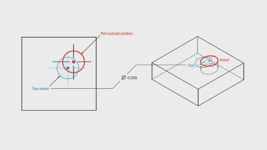
Pozycja rzeczywista to dokładna lokalizacja elementu, takiego jak otwór, sworzeń lub szczelina, zdefiniowana w odniesieniu do układów odniesienia. Po prostu mówi nam, gdzie element powinien być umieszczony na części. Zamiast skupiać się na dokładnych wartościach X i Y, definiuje strefę - zwykle okrąg lub cylinder - w której musi znajdować się środek elementu.
Strefa ta jest wyśrodkowana na teoretycznej lokalizacji, zwanej lokalizacją "nominalną". Część jest uznawana za akceptowalną, jeśli rzeczywisty środek elementu mieści się w tej strefie. Rozmiar strefy zależy od dopuszczalnej tolerancji, która jest określona w ramce kontrolnej elementu.
Na przykład, jeśli tolerancja rzeczywistego położenia otworu wynosi 0,2 mm, środek tego otworu musi mieścić się w okręgu o średnicy 0,2 mm wokół dokładnej lokalizacji docelowej. Niezależnie od tego, czy otwór przesunie się w lewo, w prawo, w górę czy w dół, nadal będzie w porządku, jeśli pozostanie wewnątrz tego okrągłego obszaru.
True Position jest często używane z innymi symbolami GD&T, takimi jak punkty odniesienia, modyfikatory stanu materiału, takie jak MMC (maksymalny stan materiału) i wymiary podstawowe. Elementy te współpracują ze sobą, aby opisać położenie, rozmiar i ograniczenia elementu w sposób bardziej przejrzysty niż tradycyjne tolerowanie.
Kluczowe symbole i terminologia
Aby pracować z True Position, ważne jest zrozumienie kluczowych symboli i terminów używanych w ramce kontrolnej elementu GD&T. Elementy te definiują, w jaki sposób stosowana jest tolerancja i jakie pomiary mają znaczenie.
- Symbol pozycji: Jest to symbol GD&T używany do reprezentowania pozycji rzeczywistej. Wygląda jak okrąg z krzyżykiem wewnątrz i jest umieszczany na początku ramki kontrolnej elementu.
- Ramka kontroli funkcji: To prostokątne pole zawiera instrukcje GD&T. Określa typ kontroli (np. położenie), wartość tolerancji, modyfikatory stanu materiału i referencyjne punkty odniesienia.
- Podstawowe wymiary: Są to idealne pomiary, zwykle w pudełku, które określają dokładną lokalizację elementu. Nie mają one tolerancji. Zamiast tego tolerancja jest definiowana przez ramkę kontrolną elementu.
- Układy odniesienia: Są to elementy referencyjne używane do pomiaru rzeczywistego położenia innych elementów. Mogą to być powierzchnie, krawędzie lub otwory oznaczone jako A, B, C itd.
- Strefa tolerancji: Jest to obszar wokół rzeczywistej pozycji, w którym może znajdować się element. Zazwyczaj jest to obszar kołowy (2D) lub cylindryczny (3D) w przypadku otworów lub kołków.
- Modyfikatory MMC i LMC: MMC (Maximum Material Condition) i LMC (Least Material Condition) umożliwiają zmianę tolerancji położenia w zależności od rozmiaru elementu. Dodatkową tolerancję można uzyskać, jeśli otwór jest większy niż jego najmniejszy dozwolony rozmiar.
Podstawowe koncepcje stojące za prawdziwą pozycją
True Position jest częścią większego systemu o nazwie GD&T. System ten został opracowany, aby zapewnić inżynierom bardziej przejrzysty i funkcjonalny sposób opisywania części. Przed złożeniem wniosku o True Position należy zrozumieć kluczowe idee.
Podstawowe ramy GD&T
GD&T to skrót od Geometric Dimensioning and Tolerancing (wymiarowanie i tolerowanie geometryczne). Wykorzystuje znormalizowany zestaw symboli do opisywania rozmiaru, kształtu, orientacji i lokalizacji elementów. Zasady te oparte są na normie ASME Y14.5.
System GD&T definiuje "idealną" wersję części. Następnie ogranicza, jak bardzo każda cecha może różnić się od tej idealnej wersji. Zamiast sprawdzać tylko odległości lub kąty, GD&T sprawdza, w jaki sposób cecha odnosi się do innych cech. Pomaga to zapewnić funkcjonalność.
Sercem GD&T jest kilka typów kontroli:
- Elementy sterujące formularza (takie jak płaskość lub zaokrąglenie) zarządzają kształtem funkcji.
- Elementy sterujące orientacją (takie jak równoległość lub prostopadłość) zarządzają kątami.
- Kontrola lokalizacji (jak pozycja) zarządza umieszczeniem.
- Elementy sterujące profilu definiują złożone powierzchnie.
True Position to rodzaj kontroli lokalizacji. Określa, jak blisko środka elementu musi znajdować się jego lokalizacja.
GD&T wykorzystuje również układy odniesieniapunkty odniesienia, linie lub płaszczyzny. Punkty odniesienia pomagają ustalić wspólne ramy dla pomiarów. Na przykład pozycja otworu jest mierzona od krawędzi lub powierzchni zdefiniowanych jako punkty odniesienia.
Pozycja rzeczywista a tolerancja liniowa
W tradycyjnej tolerancji liniowej otwór może być pokazany w odległości 50,00 ± 0,10 mm od krawędzi. Oznacza to, że można go umieścić między 49,90 mm a 50,10 mm wzdłuż jednej osi. To samo dotyczy drugiej osi. Tworzy to kwadratowe pole tolerancji.
Problem? Narożniki tego pudełka znajdują się dalej od środka niż boki. Tworzy to nierówne strefy tolerancji i nieoczekiwane rezultaty. Niektóre części mogą technicznie przejść kontrolę, ale nadal nie pasują.
True Position to naprawia. Zastępuje kwadratowe pole okręgiem. Jeśli tolerancja wynosi 0,20 mm, środek elementu musi znajdować się wewnątrz okręgu o średnicy 0,20 mm. Okrąg ten jest wyśrodkowany na podstawowej (idealnej) lokalizacji.
Zmiana ta zapewnia bardziej realistyczny i jednolity sposób pomiaru. Odpowiada on temu, jak części zachowują się w rzeczywistych zespołach. Ułatwia również kontrolę i sprawdzanie tolerancji, zwłaszcza w przypadku współrzędnościowych maszyn pomiarowych (CMM).
W skrócie:
- Tolerancja liniowa pozwala na nierównomierną zmienność.
- Prawdziwa pozycja zapewnia jednolitą i okrągłą strefę, która odzwierciedla rzeczywiste dopasowanie.
Zrozumienie ramki kontroli funkcji
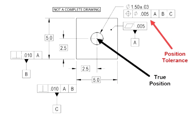
Ramka sterowania elementem to ramka zawierająca instrukcje GD&T. W przypadku True Position ramka ta zawiera wszystkie informacje na temat sposobu sterowania elementem.
Podstawowa ramka kontroli funkcji składa się z trzech części:
- Symbol - Zazwyczaj jest to symbol pozycji ⭘.
- Tolerancja - Pokazuje średnicę dozwolonej strefy. Może zawierać symbol taki jak MMC (maksymalny stan materiału).
- Odniesienia do układu odniesienia - Są to cechy używane jako punkty pomiarowe.
Oto przykład:
⭘ | 0.2 | A B C
Oznacza to:
- Cecha musi znajdować się w strefie o średnicy 0,2 mm.
- Strefa ta jest mierzona względem punktów odniesienia A, B i C.
Po dodaniu modyfikatora stanu materiału, takiego jak MMC, wygląda to następująco:
⭘ | 0.2 M | A B C
Pozwala to na dodatkową tolerancję, gdy element nie ma najgorszego rozmiaru.
Podstawowe wymiary - liczby w ramkach na wydruku - określają idealną lokalizację. Nie są one mierzone z tolerancją plus/minus. Ramka kontrolna elementu definiuje dopuszczalne odchylenia.
Jak obliczana jest prawdziwa pozycja?
Obliczanie pozycji rzeczywistej pomaga określić, czy lokalizacja elementu mieści się w dozwolonej strefie tolerancji. Przyjrzyjmy się, jak to działa, krok po kroku.
Teoretyczne wymiary dokładne (TED)
Teoretyczne wymiary dokładne (TED) to podstawowe wymiary wyświetlane na rysunku. Są to wartości w ramkach, które definiują idealną lokalizację elementu.
W przeciwieństwie do wymiarów standardowych, wymiary TED nie mają żadnej tolerancji. Zamiast tego tolerancję zapewnia ramka kontrolna elementu. Pomaga to oddzielić idealne umiejscowienie od dopuszczalnych odchyleń.
Na przykład:
- Otwór może mieć TED 50,00 mm od lewej krawędzi i 30,00 mm od dolnej krawędzi.
- Wartości te reprezentują dokładny punkt środkowy otworu na części.
- Prawdziwa pozycja otworu jest następnie sprawdzana względem tego środka.
TED muszą być zawsze używane z odniesieniami do punktów odniesienia. Tworzy to przejrzysty i powtarzalny system pomiarowy.
Podczas obliczania prawdziwej pozycji mierzy się środek rzeczywistej funkcji i porównuje go z lokalizacją opartą na TED. Różnica jest wychwytywana przez formułę.
Modyfikatory warunków materiałowych: MMC, LMC i RFS
Modyfikatory stanu materiału zmieniają dopuszczalną zmienność położenia w oparciu o rozmiar elementu. Modyfikatory te zapewniają producentom większą elastyczność bez wpływu na funkcję części.
Istnieją trzy typowe warunki:
MMC (maksymalny stan materiału):
- Jest to stan, w którym funkcja zawiera najwięcej materiału.
- W przypadku otworów oznacza to najmniejszy rozmiar otworu.
- Gdy otwór staje się większy, zyskujesz dodatkową tolerancję - nazywa się to dodatkowa tolerancja.
LMC (najmniej istotne warunki):
- Jest wręcz przeciwnie.
- W przypadku otworów jest to największy rozmiar otworu.
- Jest używana rzadziej, ale jest przydatna w przypadkach, gdy wytrzymałość części zależy od obecności materiału.
RFS (niezależnie od rozmiaru funkcji):
- Oznacza to, że tolerancja położenia pozostaje stała, niezależnie od rozmiaru elementu.
- Jest to domyślny warunek, jeśli nie podano żadnego modyfikatora.
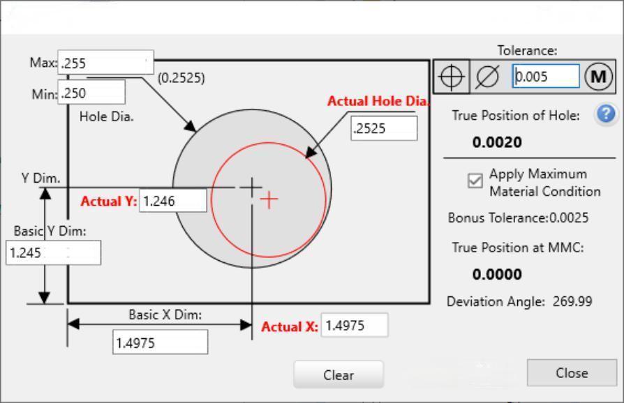
Tolerancja premii (z MMC lub LMC) jest zasadniczo prosta:
- Należy odjąć rzeczywisty rozmiar otworu od rozmiaru otworu MMC.
- Wartość ta jest dodawana do tolerancji geometrycznej.
Wzór na prawdziwą pozycję (2D i 3D)
Formuła True Position oblicza odległość od rzeczywistej zmierzonej lokalizacji elementu do jego teoretycznej lokalizacji.
Dla Pozycja 2D (płaska część, jak otwór w talerzu), wzór jest następujący:
True Position = 2 × √[(X_measured - X_theoretical)² + (Y_measured - Y_theoretical)²]
- X i Y to rzeczywiste i nominalne (teoretyczne) współrzędne.
- Współczynnik 2 uwzględnia pełną średnicę okrągłej strefy tolerancji.
Przykład:
Jeśli otwór jest mierzony w X = 49,95 mm i Y = 30,05 mm, ale TED wynosi X = 50,00 mm i Y = 30,00 mm:
Prawdziwa pozycja = 2 × √[(-0,05)² + (0,05)²]
= 2 × √[0.0025 + 0.0025]
= 2 × √0.005
= 2 × 0.0707
= 0,1414 mm
Jeśli dopuszczalna tolerancja położenia wynosi 0,2 mm, funkcja ta zostanie zaliczona.
Dla Pozycja 3Ddodaje się oś Z:
Prawdziwa pozycja = 2 × √[(XΔ)² + (YΔ)² + (ZΔ)²]
Dotyczy to elementów, które muszą być zlokalizowane w przestrzeni 3D, takich jak sworznie lub wały w częściach odlewanych lub frezowanych.
Maszyny CMM lub skanery optyczne zwykle wykonują te obliczenia podczas kontroli. Ale znajomość matematyki, która za tym stoi, pomaga w czytaniu raportów i dostosowywaniu procesów.
Układy odniesienia i ramy odniesienia
Punkty odniesienia tworzą stały układ współrzędnych, z którego można dokonywać pomiarów. W GD&T działają one jak kotwice na części. Zrozumienie układów odniesienia jest więc kluczem do prawidłowego zastosowania funkcji True Position.
Czym są punkty odniesienia?
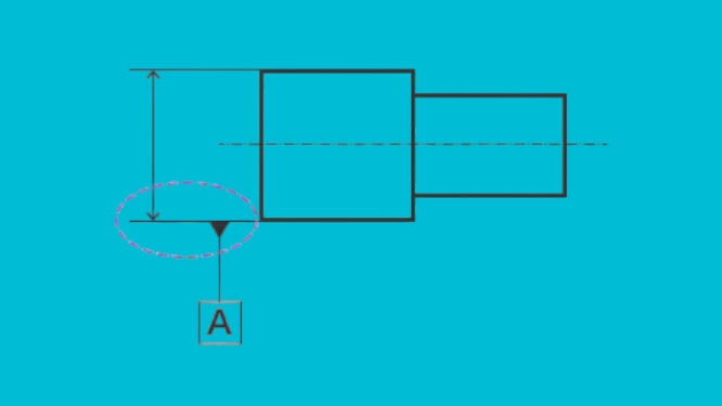
Punkt odniesienia to fizyczna cecha części - taka jak płaska powierzchnia, otwór lub krawędź - która służy jako odniesienie. Służy on do tworzenia ram pomiarowych.
Każdy układ odniesienia ustanawia jedną lub więcej osi lub płaszczyzn:
- A powierzchnia ustawia płaską płaszczyznę odniesienia.
- A szczelina lub otwór można ustawić środek elementu, definiując oś lub punkt.
- Wiele układów odniesienia razem definiuje układ współrzędnych 3D.
Na rysunkach punkty odniesienia są oznaczone dużymi literami (A, B, C) i połączone z elementem za pomocą linii odniesienia lub symbolu.
Punkty odniesienia muszą być:
- Powtarzalność kontroli
- Stabilność podczas produkcji
- Funkcjonalne dla końcowego zastosowania części
Pomagają one zapewnić dokładność i spójność pomiarów w różnych konfiguracjach produkcji i kontroli.
Jak układy odniesienia wpływają na rzeczywistą pozycję?
Prawdziwa pozycja jest zawsze mierzona względem jednego lub więcej punktów odniesienia. Te punkty odniesienia definiują orientację i położenie części w przestrzeni.
Gdy ramka kontrolna funkcji zawiera listę punktów odniesienia (takich jak A | B | C), każdy z nich blokuje się w określonym kierunku:
- Datum A ustawia główną płaszczyznę (zazwyczaj płaską podstawę).
- Datum B ustawia drugorzędny kierunek (np. wyrównanie do lewej/prawej).
- Datum C definiuje trzeci kierunek (kontrola głębokości lub obrotu).
Kolejność punktów odniesienia ma znaczenie. Wpływa ona na sposób mocowania, pomiaru i kontroli części.
Po ustaleniu punktów odniesienia:
- Podstawowe wymiary (TED) definiują idealną lokalizację elementu na podstawie tych punktów odniesienia.
- Zmierzona pozycja elementu jest następnie porównywana z tą teoretyczną lokalizacją.
- Tolerancja pozycji rzeczywistej definiuje dopuszczalną strefę.
Jeśli część nie jest wyrównana do prawidłowych punktów odniesienia podczas kontroli, wyniki będą błędne - nawet jeśli element został wykonany prawidłowo.
Kolejność i strategia wyboru układu odniesienia
Kolejność punktów odniesienia w ramce kontrolnej elementu definiuje sposób ustawienia części podczas pomiaru. Kolejność określa:
- Która powierzchnia jest utrzymywana jako pierwsza (podstawowa)
- Jaka powierzchnia jest utrzymywana jako druga (drugorzędna)?
- Jaka powierzchnia jest utrzymywana jako trzecia (trzeciorzędowa)?
Każdy kolejny krok blokuje część w przestrzeni.
Oto jak wybrać układ odniesienia:
- Podstawowy układ odniesienia (A): Wybierz największą, najbardziej stabilną i funkcjonalną powierzchnię. Powinna ona wspierać część podczas użytkowania lub montażu.
- Wtórny układ odniesienia (B): Wybierz powierzchnię prostopadłą do A. Pomaga to zorientować część od lewej do prawej lub od przodu do tyłu.
- Trzeciorzędowy układ odniesienia (C): Zwykle blokuje to część w ostatecznym kierunku, takim jak obrót lub wysokość.
Dobry wybór punktów odniesienia odzwierciedla sposób, w jaki część jest montowana lub używana w rzeczywistości. Jeśli zostaną wybrane niewłaściwe punkty odniesienia, elementy mogą być mierzone nieprawidłowo - nawet jeśli zostały starannie wykonane.
Na przykład, jeśli otwór montażowy musi znajdować się w jednej linii z wspornikPowierzchnia skierowana do wspornika powinna być jednym z punktów odniesienia. W ten sposób lokalizacja otworu jest mierzona na podstawie tego, jak część zostanie zainstalowana - a nie tylko jak wygląda na papierze.
Techniki kontroli i pomiarów
Po wyprodukowaniu części następnym krokiem jest sprawdzenie, czy cechy spełniają wymagania rysunku. W przypadku elementów z funkcją True Position oznacza to sprawdzenie, czy mieszczą się one w dozwolonej strefie tolerancji. W tym celu dostępnych jest kilka narzędzi i metod.
Metody CMM (współrzędnościowej maszyny pomiarowej)
A CMM jest jednym z najdokładniejszych i najczęściej używanych narzędzi do sprawdzania pozycji rzeczywistej. Działa poprzez sondowanie powierzchni części i rejestrowanie współrzędnych każdej cechy.
Oto jak to działa:
- Część jest montowana w uchwycie.
- Maszyna wyrównuje je przy użyciu zdefiniowanych punktów odniesienia (A, B, C).
- Sonda dotyka elementu, takiego jak ściana lub powierzchnia otworu.
- Oprogramowanie porównuje rzeczywiste centrum z lokalizacją opartą na TED.
- Oblicza prawdziwą pozycję przy użyciu standardowego wzoru.
Korzyści z używania współrzędnościowej maszyny pomiarowej:
- Wysoka precyzja i powtarzalność
- Pomiary 2D i 3D
- Automatyczne przechwytywanie danych i raportowanie
- Łatwa obsługa wielu funkcji i wzorów
Współrzędnościowe maszyny pomiarowe są idealne do części o wąskich tolerancjach, złożonej geometrii lub dużych zestawach elementów. Wymagają one jednak czasu konfiguracji i są zwykle używane w laboratoriach kontroli jakości, a nie na hali produkcyjnej.
Wskaźniki zegarowe i trzpienie pomiarowe
Wybieranie wskaźniki I kołki pomiarowe zapewniają szybkie, ręczne sposoby sprawdzania rzeczywistej pozycji dla prostszych części lub kontroli na hali produkcyjnej.
Metoda sworznia pomiarowego:
- Użyj szpilki pasującej do rozmiaru elementu.
- Włóż go do otworu lub szczeliny.
- Użyj czujnika zegarowego, aby przesunąć sworzeń i zmierzyć, jak daleko jego środek znajduje się od TED.
Przemiatanie wskaźnika zegarowego:
- Zamontuj część na stole obrotowym lub uchwycie.
- Użyj czujnika zegarowego na statywie wysokościowym lub uchwycie testowym.
- Przeciągnij po powierzchni lub krawędzi elementu.
- Sprawdź odchylenie od oczekiwanej pozycji.
Metoda ta sprawdza się w przypadku dużych otworów lub elementów o dużej tolerancji. Jest szybka i nie wymaga oprogramowania. Jest jednak mniej precyzyjna niż współrzędnościowa maszyna pomiarowa i bardziej podatna na błędy użytkownika. Najlepiej stosować ją w przypadku podstawowych części lub szybkich kontroli w trakcie procesu.
Wnioski
True Position w GD&T precyzyjnie kontroluje położenie elementu przy użyciu kołowej lub cylindrycznej strefy tolerancji. Oferuje lepszą dokładność i elastyczność niż tradycyjne tolerancje ±. Inżynierowie mogą jasno określić, jak daleko element może odbiegać od dokładnej pozycji, używając podstawowych wymiarów, referencyjnych punktów odniesienia i modyfikatorów, takich jak MMC.
Potrzebujesz pomocy w zastosowaniu zasad GD&T, takich jak True Position, do niestandardowych części metalowych? Skontaktuj się z nami już dziś aby uzyskać fachowe wsparcie i szybkie rozwiązania produkcyjne dostosowane do Twoich potrzeb.
Hej, jestem Kevin Lee

Przez ostatnie 10 lat byłem zanurzony w różnych formach produkcji blach, dzieląc się tutaj fajnymi spostrzeżeniami z moich doświadczeń w różnych warsztatach.
Skontaktuj się z nami
Kevin Lee
Mam ponad dziesięcioletnie doświadczenie zawodowe w produkcji blach, specjalizując się w cięciu laserowym, gięciu, spawaniu i technikach obróbki powierzchni. Jako dyrektor techniczny w Shengen, jestem zaangażowany w rozwiązywanie złożonych wyzwań produkcyjnych i napędzanie innowacji i jakości w każdym projekcie.
Powiązane zasoby

Odporna na odciski palców stal nierdzewna: jak to działa i jak wybrać


