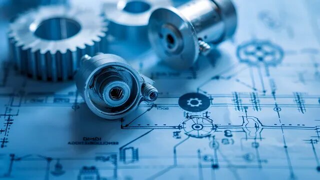
Machined parts perform well when the design supports real cutting conditions. Many issues begin in the CAD stage, long before a tool enters the material. Small choices—such as pocket depth, corner radius, tolerances, or thread size—can significantly impact cost, surface finish, cycle time, and inspection work.
Industry surveys indicate that over half of machining problems stem from design-related decisions, rather than machining skill. This means most delays, reworks, and unexpected expenses can be prevented early. The following sections outline the nine major mistakes to avoid and explain how engineers can address them early in the project.
Mistake 1 — Designing Features That Tools Cannot Reach
Some features appear simple on-screen but are difficult—or even impossible—to automate with a machine. Tooling always has diameter, length, and deflection limits. Internal sharp corners, narrow deep pockets, organic curves, and small slots often violate these limits.
Cutters must reach the area with enough rigidity to avoid vibration. When tools become too long, deflection increases sharply. A long-reach end mill may require slower feeds, more finishing passes, and multiple setups. Deep pockets can take 2–3× longer than shallow ones because the cutter cannot remove material aggressively.
Real-World Indicators of an Unreachable Feature
- A perfect 90° internal corner with 0 mm radius
- Pocket deeper than 3× its width
- Slot width smaller than standard end mills
- Geometry requiring 5-axis access, even though the part can be simplified
- Surfaces reachable only by custom tools
These red flags typically lead to slow machining, high cost, or redesign requests.
Improved vs. Poor Design Example
| 特集 | Poor Design | Improved Design |
|---|---|---|
| Internal corners | 0 mm radius | 3 mm radius (fits common Ø6 mm tool) |
| 6 mm wide × 20 mm deep | 10 mm wide × 10 mm deep | |
| Slot | 1 mm width | 2 mm+ width using standard cutters |
Practical adjustments like these reduce machining time, tool wear, and vibration.
How to Fix It Early?
- Add internal radii that match available tool diameters
- Keep deep pockets shallow, or widen them to improve cutter access
- Break complex parts into two simpler machined components
- Review tool access when designing ribs, channels, or undercuts
- Confirm machining axis capability before finalizing geometry
These steps directly improve machining efficiency, reduce cost, and support consistent CNC machining results.
Mistake 2 — Specifying Tolerances Tighter Than Necessary
Tolerances control how closely a dimension must match the CAD model. However, many designs apply tight tolerances to non-critical features. This results in unnecessary machining passes, increased inspection, and higher scrap rates.
Precision cutting requires slow feed rates and small stepovers. A tight tolerance moves machining from a standard pass to a fine-finishing pass. Shop data shows that acceptable tolerances can increase machining time by 20–30%, especially for holes, slots, and precision faces. It also requires more probing and metrology.
Where Tight Tolerances Truly Matter?
- Bearing fits
- Locating bosses
- Mating sliding surfaces
- Press-fit or interference-fit features
- Datum surfaces that control assembly alignment
All other features can often use standard general tolerances without affecting performance.
Poor vs. Improved Tolerance Design
| 特集 | Poor Design | Improved Design |
|---|---|---|
| Outer profile | ±0.01 mm | ±0.1 mm general tolerance |
| Non-functional slot | ±0.02 mm | ±0.1 mm |
| Mating pin fit | ±0.1 mm | ±0.01 mm (functional) |
This approach preserves function while reducing machining cost and inspection load.
How to Fix It Early?
- Identify functional features first, then apply tight tolerances selectively
- Use general tolerances (±0.1–0.2 mm) on non-critical areas
- Avoid unnecessary GD&T symbols unless they add functional clarity
- Review the tolerance stack-up with the machinist before finalizing drawings
These steps improve manufacturability and reduce risk during CNC machining. Clear and appropriate tolerance design directly reduces CNC machining cost, improves reliability, and supports high-quality production for both prototypes and volume parts.
Mistake 3 — Designing Thin Walls or Very Deep Cavities
Thin walls and deep pockets reduce rigidity. During cutting, tools push against material, and weak geometry bends or vibrates. Even a slight flex can cause chatter, dimensional drift, or a poor surface finish.
Cutting tools have a practical length-to-diameter limit. When a tool extends beyond 4–5× its diameter, deflection rises sharply. Thin walls behave the same way—without support, they move under cutting forces. Many shops slow feed rates significantly to avoid vibration, which increases cycle time.
Typical Red Flags
- Aluminum walls thinner than 1.0–1.5 mm
- Pocket depth greater than 3–4× pocket width
- Long-reach tools are required for multiple internal levels
- Tall, slender features showing vibration marks
These conditions often trigger discussions about slow machining, multi-pass finishing, or redesign.
Poor vs. Improved Geometry Example
| 特集 | Poor Design | Improved Design |
|---|---|---|
| Wall thickness | 0.8 mm | 1.5–2.0 mm |
| Pocket depth | 25 mm deep × 6 mm wide | 12 mm deep × 10 mm wide |
| Rib height | 40 mm tall with thin base | 25 mm tall with thicker base |
Improved geometry increases rigidity, reduces chatter, and shortens cycle time.
How to Fix It Early?
- Use thicker walls where possible
- Shorten deep cavities or widen the opening
- Add ribs or support features to stiffen tall structures
- Split very deep or complex features into two machined parts
- Keep the cutter reach within stable tool ratios
Adding a few millimeters to the wall thickness can prevent hours of extra machining time.
Mistake 4 — Ignoring Material Machinability
Material selection significantly impacts cycle time, tool wear, thermal behavior, and dimensional stability. Many delays occur because a material is chosen for its strength or appearance without considering its machining performance.
Harder or gummy materials require slower feeds, stronger cutters, and more cooling. Industry machining benchmarks indicate that machining complex alloys, such as stainless steel or titanium, can increase machining time by 30–50%. These materials also demand more tool changes and careful monitoring.
Common Machinability Differences
| 素材 | Behavior During Machining |
|---|---|
| アルミニウム6061 | Excellent machinability, cool cutting |
| ステンレス304 | Work-hardens, requires slower passes |
| Titanium Grade 5 | Generates heat, stresses tools |
| Brass / Copper | Easy to machine but expensive |
Understanding these differences helps match performance and cost.
How to Fix It Early?
- Choose alloys that balance strength and machinability
- Use aluminum for prototypes unless the function requires steel
- Confirm whether heat treatment is applied before or after machining
- Avoid unnecessary premium alloys in non-critical parts
Wise material choices reduce tool wear and improve surface quality.
Mistake 5 — Over-Complicating the Geometry
Many CAD models become more complex than necessary. This often occurs when designers replicate features from molded, キャスト、 または 3D-printed parts into a machined design—machining favors simple geometry and clean surfaces.
Complex features usually require:
- Extra setups
- Custom fixturing
- Specialized cutters
- Multi-axis machining
- More surface finishing
These steps increase cost without improving part performance. Engineers often redesign these features after reviewing CAM toolpaths.
Poor vs. Improved Design Example
| Problem Area | Poor Design | Improved Design |
|---|---|---|
| Organic curves | Sculpted surfaces | Planar faces + simple profiles |
| Decorative recess | Deep contour | Shallow or removed recess |
| Undercuts | Internal undercut | Split part or redesign for access |
Simpler geometry returns the part to stable, predictable machining.
How to Fix It Early?
- Replace decorative surfaces with planar or cylindrical forms
- Reduce unnecessary pockets or deep contours
- Avoid rounded organic shapes unless the function requires them
- Validate whether complex surfaces increase setup count
- Review the geometry with a machinist before locking the design
This reduces risk and improves repeatability for both prototypes and production runs.
Mistake 6 — Neglecting Fixturing and Setup Requirements
Every machine part needs to be held rigidly. A design that looks stable in CAD may be difficult to clamp in reality. When there are no flat reference surfaces or clear datums, the machinist must create custom fixtures or flip the part multiple times to ensure accurate positioning.
Each additional setup introduces variation and consumes time. Many machining workshops report that each extra setup can add 10–20% to total machining time due to re-probing, re-aligning, and verifying accuracy. More setups also increase the chance of tolerance stack-up errors.
Common Fixturing Red Flags
- Curved surfaces on all sides with no flat area for clamping
- Tall features that do not allow stable gripping
- Geometry that forces the machinist to rotate the part multiple times
- Critical dimensions located on surfaces from different orientations
- Parts requiring custom soft jaws or vacuum fixtures
These issues lead to unnecessary costs and sometimes rejected designs.
Poor vs. Improved Fixturing Design Example
| Issue | Poor Design | Improved Design |
|---|---|---|
| Clamping surfaces | Fully curved exterior | One added flat for gripping |
| Setup count | 4 setups required | 2 setups after redesign |
| Datum choice | No clear primary face | Dedicated flat datum A |
Simple flat surfaces or better datum planning can significantly reduce the setup count.
How to Fix It Early?
- Add at least one flat, stable face for clamping
- Keep as many critical features as possible on one orientation
- Avoid forcing contact points on thin or fragile surfaces
- Check whether the part can be machined in 2 or fewer setups
- Split very complex shapes into two simpler components
These adjustments improve stability, accuracy, and lead time.
Mistake 7 — Using Non-Standard Hole Sizes, Threads, or Depths
Holes and threads are among the most frequently encountered machining features, yet they often cause preventable issues. Problems occur when designs specify custom diameters, deep threads, or uncommon thread types.
Standard drill sizes and thread tools follow established charts. When a design uses non-standard values, the machinist may require special cutters or slower feed rates. Deep threads create even more problems — excessive depth increases the risk of tap breakage, especially in tough materials like stainless steel or titanium.
Industry practice suggests that increasing the thread depth beyond 2–3 times the nominal diameter rarely improves strength, but significantly increases machining time.
Common Red Flags
- Hole diameters that don’t match standard drills
- Thread depths exceeding functional requirements
- Threads located too close to walls or thin features
- Missing chamfers at thread entry points
- Use of exotic thread types in simple parts
These issues slow down drilling, tapping, and inspection.
Poor vs. Improved Hole/Thread Design Example
| 特集 | Poor Design | Improved Design |
|---|---|---|
| Thread depth | 5× diameter | 1.5–2× diameter (typical) |
| Hole diameter | 7.3 mm custom | 7.0 or 7.5 mm standard drill |
| Thread entry | No chamfer | 0.5–1.0 mm chamfer |
Minor adjustments ensure better tool life and more reliable machining.
How to Fix It Early?
- Select hole sizes from standard drill charts
- Use practical thread depths for material type
- Add chamfers for clean thread starts
- Keep threads away from thin walls
- Choose the familiar thread series unless the function demands otherwise
These actions reduce tooling issues and improve machining consistency.
Mistake 8 — Overlooking Post-Processing Effects
Most machined parts require 仕上げ, which may include anodizing, plating, polishing, bead blasting, or heat treatment. These processes change surface thickness, hardness, and final dimensions. Problems appear when the design ignores these changes.
Finishes the surface with the building material. Hard anodizing, for instance, adds 0.005–0.015 mm per side, depending on process and color. Plating and heat treatment can introduce slight warping. If the drawing does not account for this, the part may fail inspection or fit poorly during assembly.
Common Oversights
- Tight-tolerance holes machined before anodizing
- Thin walls deforming during heat treatment
- No allowance for coating buildup
- The assembly fits with a loss of clearance after plating
- Threads made before anodizing and then clogging
These issues often arise when the part is nearly complete, necessitating rework or replacement of the part.
Poor vs. Improved Finishing Planning Example
| Issue | Poor Design | Improved Design |
|---|---|---|
| Anodized hole | Machined to final Ø | Undersized → reamed after anodizing |
| Heat-treated part | Thin walls warp | Thicker walls + stress-relief process |
| Coating clearance | Zero allowance | 0.01–0.02 mm per side allowed |
Planning the finishing sequence early prevents size drift and coating-related failures.
How to Fix It Early?
- Apply tight tolerances その後 仕上げ
- Undersize key holes and ream them post-anodizing
- Use stable alloys when heat treatment is needed
- Validate that the assembly fits with the coating thickness included
- Add drawing notes specifying finishing sequence
This ensures coating or heat processes do not compromise precision.
Mistake 9 — Not Consulting the Machinist Early
This is one of the most expensive mistakes. Many design issues—such as tool reach, tolerance extremes, weak walls, or non-standard threads—can be identified in minutes by a machinist but may take days to fix later.
Manufacturing surveys indicate that early DFM review can reduce machining costs by 20–40% by eliminating unnecessary features, refining setup plans, and eliminating complex geometry. Early communication also prevents long email cycles and late-stage drawing revisions.
Issues Commonly Found During Early Review
- Overly tight tolerances that add no functional value
- Deep pockets requiring long-reach tools
- Thin walls risk deflection
- Threads placed near weak edges
- Setups that could be consolidated
- Material choices mismatched to machining requirements
A brief review can prevent significant problems later.
How to Fix It Early?
- Send CAD files for early manufacturability checks
- Ask which features increase setup count
- Confirm tool availability and machine size
- Discuss material machinability and finishing requirements
- Validate that tolerance stack-ups reflect functional intent
These steps create a smoother path from CAD to final parts. Early collaboration with machinists improves CNC machining quality, reduces cost, and prevents redesigns by identifying issues before production begins.
結論
Most machining problems can be prevented long before they occur in production. The key is designing with absolute tooling limits, choosing materials that machine well, avoiding unnecessary complexity, planning finishing processes, and involving machinists early in the process. When CAD design supports cutting conditions, parts are more accurate, cycle times drop, and costs become predictable.
Machining is most effective when designers and suppliers work together. Precise drawings, stable features, smart tolerances, and early reviews enable the creation of reliable parts from prototype to mass production.
If you need a quick manufacturability check or want to validate tolerance choices, setup counts, or finishing impacts, you can share your CAD files. An early review often prevents redesigns and helps achieve smoother machining results.
ケビン・リー
レーザー切断、曲げ加工、溶接、表面処理技術を専門とし、板金加工において10年以上の実務経験があります。シェンゲンのテクニカルディレクターとして、複雑な製造上の課題を解決し、各プロジェクトにおける革新と品質の向上に尽力しています。


