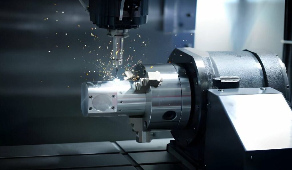
Il lavoro di lavorazione si scontra spesso con problemi quali la lentezza, l'aumento dei costi e l'usura degli utensili. Molti ingegneri e direttori di officina cercano di accelerare i tempi, ma si preoccupano di perdere la qualità dei pezzi. Potreste esservi imbattuti nel termine "SFM" durante una riunione o mentre sfogliavate il manuale di una macchina. Non ci avete prestato molta attenzione. Potreste persino chiedervi se è qualcosa che dovete sapere.
La verità è che se non si capisce cosa significa SFM, diventa molto più difficile ottenere il massimo dalle proprie macchine. Sapere come funziona può aiutarvi a tagliare più velocemente, a proteggere gli utensili e a tenere sotto controllo i costi. Ecco una chiara introduzione all'SFM e al suo collegamento con le basi della lavorazione.
Che cos'è l'SFM nella lavorazione?
SFM significa "Surface Feet per Minute". Misura la velocità con cui il tagliente dell'utensile si muove sulla superficie del materiale. Questa velocità dipende dalla velocità di rotazione dell'utensile e dalle sue dimensioni.
Se un utensile da taglio gira troppo lentamente, il taglio potrebbe non essere pulito. Se gira troppo velocemente, l'utensile può surriscaldarsi o usurarsi rapidamente. L'SFM fornisce un numero che aiuta a trovare la velocità giusta.
Questo numero è utile per selezionare le velocità di frese, torni o trapani. Si applica sia all'utensile che al materiale. Materiali diversi hanno bisogno di SFM diverse per tagliare bene ed evitare problemi.
Perché l'SFM è importante per la lavorazione?
Il giusto SFM mantiene gli utensili affilati più a lungo e fornisce finiture più uniformi. Inoltre, aiuta a evitare il surriscaldamento, le vibrazioni e la scarsa qualità dei pezzi. L'uso di un SFM sbagliato può far perdere tempo, danneggiare i pezzi e usurare rapidamente gli utensili.
Ogni combinazione di materiale e utensile ha un intervallo SFM consigliato. Il rispetto di questo intervallo contribuisce alla coerenza. Inoltre, riduce i costi di produzione e di sostituzione degli utensili.
I macchinisti utilizzano l'SFM per impostare la corretta velocità del mandrino (RPM). La regolano in base alle dimensioni dell'utensile e al tipo di materiale. Questo rende la lavorazione più sicura e affidabile.
Le basi dei piedi di superficie al minuto
L'SFM aiuta i macchinisti a scegliere la velocità con cui un utensile deve muoversi sul materiale. Questa sezione spiega cosa significa e come si usa in officina.
Definire l'SFM in termini pratici
SFM indica la distanza percorsa dal tagliente dell'utensile sulla superficie in un minuto. L'unità di misura è in piedi al minuto. Si basa sulla velocità di rotazione dell'utensile e sulle sue dimensioni.
Ad esempio, se si utilizza un utensile di grande diametro, questo coprirà una superficie maggiore allo stesso numero di giri rispetto a uno piccolo. L'SFM aiuta ad adattare il movimento dell'utensile al lavoro e al materiale.
È un modo per controllare la velocità di taglio con numeri reali. I macchinisti utilizzano tabelle o formule SFM per scegliere la velocità giusta per ogni utensile e materiale.
Come l'SFM si rapporta alla velocità di taglio?
La velocità di taglio è la velocità con cui il materiale incontra l'utensile da taglio. L'SFM è un modo per misurare tale velocità. Si concentra sul punto di contatto della superficie, dove l'utensile tocca il pezzo.
Se l'SFM è troppo alto, l'utensile può usurarsi o guastarsi. Se è troppo basso, il taglio può risultare ruvido o lento. Un buon SFM significa un migliore controllo del truciolo, una migliore finitura superficiale e una maggiore durata dell'utensile.
La velocità di taglio è essenziale sia per tornitura e fresatura. L'SFM facilita il confronto delle velocità di taglio tra macchine e lavori.
Differenze tra SFM e RPM
SFM e RPM sono collegati, ma non sono la stessa cosa. L'SFM misura la velocità con cui l'utensile si muove sulla superficie del materiale. Il numero di giri è la velocità di rotazione dell'utensile in un minuto.
L'SFM dipende sia dal numero di giri che dal diametro dell'utensile. Un utensile più grande ha bisogno di meno giri al minuto per raggiungere lo stesso SFM. Un utensile più piccolo ha bisogno di più giri al minuto per raggiungere la stessa velocità.
Quindi, quando si cambia utensile, è necessario regolare il numero di giri per mantenere lo stesso SFM. Ecco perché i macchinisti calcolano entrambi prima di iniziare un taglio.
Come calcolare l'SFM?
Per utilizzare l'SFM nei lavori reali, è necessario sapere come calcolarlo. Questa parte spiega la formula, gli input necessari e come assicurarsi che i numeri siano corretti.
Formula per l'SFM
La formula standard per l'SFM è:
SFM = (π × Diametro utensile × RPM) ÷ 12
Questo dà la velocità della superficie in piedi al minuto. Si usa π (circa 3,1416) perché si tratta del movimento circolare dell'utensile.
Questa formula consente di determinare la velocità di movimento del tagliente sulla superficie esterna dell'utensile.
Variabili chiave: Diametro e numero di giri
Le variabili principali della formula SFM sono due: il diametro dell'utensile e la velocità del mandrino (RPM).
- Diametro è la dimensione dell'utensile sul suo tagliente, solitamente in pollici.
- NUMERO DI GIRI è il numero di giri dell'utensile in un minuto.
Entrambi i valori lavorano insieme. Un diametro maggiore significa una maggiore superficie percorsa per ogni giro. Un numero di giri più alto aumenta il numero di giri al minuto. La modifica di uno dei due valori influisce sull'SFM.
Unità di misura
L'SFM è misurato in piedi al minuto.
Per far funzionare la formula:
- Il diametro dell'utensile deve essere in pollici
- RPM è sempre il numero di giri al minuto
- Dividere per 12 per trasformare i pollici in piedi (dato che ci sono 12 pollici in un piede).
Assicurarsi che tutte le unità siano corrette prima di calcolare. Se si mescolano pollici e millimetri, il risultato sarà sbagliato. Ricontrollare sempre i dati immessi.
Come convertire SFM in RPM?
A volte si conosce l'SFM desiderato, ma è necessario trovare il numero di giri corretto per la macchina. Questa sezione mostra come invertire la formula SFM e ottenere la velocità del mandrino corretta.
Per convertire SFM in RPM, utilizzare questa formula:
RPM = (SFM × 12) ÷ (π × Diametro utensile)
Questo valore indica la velocità del mandrino in giri al minuto.
Sono necessarie due cose:
- L'SFM target per il materiale che si sta tagliando
- Il diametro dell'utensile in pollici
Questa formula aiuta a impostare correttamente la macchina. Evita l'uso di una velocità sbagliata, che può usurare gli utensili o danneggiare il pezzo.
Supponiamo che l'SFM consigliato sia 300 e che il vostro utensile abbia un diametro di 1 pollice. Allora:
GIRI/MIN = (300 × 12) ÷ (3,1416 × 1)
RPM ≈ 1146
Quindi, si dovrebbe impostare il mandrino a circa 1146 giri/min. Utilizzare una calcolatrice o un grafico SFM per risparmiare tempo quando si esegue questa operazione.

SFM per materiale del pezzo
Materiali diversi richiedono velocità di taglio diverse. Questa sezione mostra i valori SFM comuni per i materiali più diffusi e come la durezza influisce sui numeri.
SFM ideale per alluminio, acciaio, titanio e materie plastiche
Ogni materiale ha un intervallo SFM consigliato. Questi valori aiutano a bilanciare la velocità di taglio, la durata dell'utensile e la finitura del pezzo.
- Alluminio: Da 300 a 1.000 SFM
L'alluminio è morbido e si taglia facilmente. È possibile utilizzare velocità elevate senza danneggiare l'utensile.
- Acciaio dolce: Da 100 a 300 SFM
L'acciaio è più rigido dell'alluminio. Ha bisogno di velocità più basse per evitare l'accumulo di calore e l'usura degli utensili.
- Acciaio inossidabile: Da 50 a 200 SFM
L'acciaio inossidabile è robusto e si indurisce rapidamente. Un SFM più basso contribuisce a ridurre le sollecitazioni e a prolungare la vita dell'utensile.
- Titanio: Da 30 a 70 SFM
Il titanio è forte ma difficile da tagliare. Ha bisogno di velocità ridotte per controllare il calore ed evitare guasti all'utensile.
- Plastica: Da 500 a 1500 SFM
Le materie plastiche variano notevolmente. Le plastiche più morbide sono in grado di sopportare velocità elevate, mentre le plastiche dure o cariche possono richiedere velocità più basse per evitare la fusione o la scheggiatura.
Si tratta di intervalli generali. Controllare sempre le specifiche dell'utensile e del materiale per ottenere numeri più precisi.
Regolazione dell'SFM in base alla durezza del materiale
I materiali più duri necessitano di un SFM più lento. I materiali più morbidi possono utilizzare un SFM più elevato. Questa regola consente di evitare danni agli utensili e l'accumulo di calore.
Ad esempio, il taglio di acciaio temprato con un SFM elevato può opacizzare rapidamente l'utensile. Il taglio di alluminio morbido con un basso SFM può causare una finitura scadente e lunghi tempi di ciclo.
Anche il rivestimento dell'utensile e il tipo di materiale sono importanti. Gli utensili in metallo duro consentono un SFM più elevato. Gli utensili in acciaio ad alta velocità possono richiedere un SFM inferiore a parità di materiale.
Regolare l'SFM in base a:
- Durezza del materiale
- Materiale dell'utensile
- Capacità della macchina
Iniziare con l'estremità bassa della gamma, quindi aumentare se il taglio è pulito e l'utensile rimane freddo.
SFM vs. velocità di avanzamento
L'SFM e la velocità di avanzamento lavorano insieme durante il taglio. Questa sezione spiega come interagiscono e come bilanciarli per ottenere migliori risultati di lavorazione.
Comprendere la relazione tra velocità e avanzamento
L'SFM controlla la velocità del bordo dell'utensile sul materiale. La velocità di avanzamento è la velocità con cui l'utensile si muove nel materiale.
Se l'SFM è troppo alto ma l'avanzamento è troppo basso, l'utensile potrebbe sfregare invece di tagliare. Se l'avanzamento è troppo alto ma l'SFM è troppo basso, l'utensile potrebbe scheggiarsi o sovraccaricarsi.
Entrambi devono combaciare per ottenere tagli puliti e un buon flusso di trucioli. Una mancata corrispondenza può portare all'usura dell'utensile, a una scarsa finitura superficiale o allo stress della macchina.
Bilanciamento dell'SFM con l'avanzamento per dente o per giro
La velocità di avanzamento è spesso indicata come:
- Avanzamento per dente (FPT) per la fresatura
- Avanzamento per giro (IPR) per la rotazione
Per calcolare la velocità di avanzamento completa:
Velocità di avanzamento = RPM × Numero di denti × FPT
Per la tornitura:
Velocità di avanzamento = RPM × IPR
Una volta che si conosce l'SFM e lo si utilizza per ottenere il numero di giri, è possibile calcolare l'avanzamento. L'obiettivo è far coincidere l'avanzamento con l'SFM in modo che l'utensile tagli, non sfreghi o si sovraccarichi.
Un SFM più elevato di solito significa un avanzamento più elevato. Ma l'avanzamento deve rimanere entro i limiti dell'utensile e della macchina.
Quando dare la priorità all'uno piuttosto che all'altro?
Se la finitura superficiale è fondamentale, iniziare a regolare l'SFM. Un avanzamento più basso con un SFM corretto consente di ottenere una superficie più liscia.
Se la velocità di produzione è più importante, concentrarsi sulla velocità di avanzamento. Utilizzate l'avanzamento più elevato che l'utensile e il pezzo possono gestire, quindi regolate l'SFM in modo che corrisponda.
Monitorare costantemente l'usura dell'utensile e la forma dei trucioli. Se i trucioli sono troppo delicati o polverosi, l'avanzamento potrebbe essere troppo basso. Se i trucioli sono spessi e l'utensile si scheggia, l'avanzamento potrebbe essere troppo elevato.
Effetti dell'SFM sulle prestazioni di lavorazione
L'SFM influisce direttamente sulle prestazioni di utensili, pezzi e macchine. Questa sezione analizza come cambia la durata degli utensili, la finitura superficiale, il calore e il controllo dei trucioli.
Impatto sulla durata dell'utensile
L'SFM ha un effetto significativo sulla durata degli utensili. Se l'SFM è troppo alto, il bordo dell'utensile si scalda troppo e si consuma più rapidamente. Se è troppo basso, l'utensile può sfregare invece di tagliare, causando anch'esso l'usura.
Rimanere nella giusta gamma di SFM aiuta gli utensili a tagliare in modo pulito. Riduce la possibilità di scheggiature o rotture. Inoltre, evita la necessità di cambiare continuamente gli utensili, risparmiando tempo e denaro.
Utilizzate utensili rivestiti? Spesso consentono di ottenere un SFM più elevato, ma solo se la rimozione dei trucioli e il raffreddamento sono sotto controllo.
Influenza sulla finitura superficiale
Il giusto SFM aiuta a creare superfici lisce. Se l'SFM è troppo alto, il taglio può risultare ruvido a causa delle vibrazioni o della deviazione dell'utensile. Se è troppo basso, l'utensile può lasciare segni o bordi irregolari.
Un SFM stabile mantiene l'utensile agganciato correttamente. Taglia invece di trascinare. In questo modo la finitura è più pulita e uniforme, soprattutto nei lavori di finitura.
Nella maggior parte dei casi, un SFM più elevato con un avanzamento inferiore offre risultati migliori in termini di superficie, ma è comunque necessario rimanere entro limiti di sicurezza.
Ruolo nella generazione di calore e nel controllo dei chip
Un SFM più elevato aumenta il calore sul tagliente. Il calore ammorbidisce l'utensile e il materiale, causando guasti all'utensile o tagli di scarsa qualità. È possibile ridurre questo fenomeno utilizzando refrigeranti o scegliendo rivestimenti migliori per gli utensili.
L'SFM cambia anche il modo in cui i trucioli si rompono e scorrono. Con il giusto SFM, i trucioli sono piccoli e si arricciano in modo pulito. Con un SFM sbagliato, i trucioli possono attaccarsi, intasarsi o formare lunghe corde che danneggiano il pezzo.

SFM e limitazioni della macchina
Anche se i calcoli sembrano corretti, la macchina potrebbe non essere in grado di eseguire i numeri. Questa sezione spiega come i limiti della macchina influenzano le scelte dell'SFM e cosa fare quando la teoria e la realtà non coincidono.
Vincoli di numero di giri massimo e di potenza del mandrino
Ogni macchina ha un limite massimo di giri e di potenza del mandrino. Se il numero di giri calcolato per l'SFM desiderato è troppo alto, la macchina potrebbe non raggiungerlo.
Ad esempio, gli utensili di piccole dimensioni necessitano di un numero di giri elevato per ottenere il giusto SFM. Ma alcune macchine arrivano al massimo a 6.000 o 8.000 giri/min. Questo può costringervi a lavorare al di sotto dell'SFM ideale.
Anche la potenza del mandrino è importante. Un SFM elevato su utensili di grandi dimensioni o materiali duri può richiedere una coppia superiore a quella che la macchina è in grado di fornire. Una velocità eccessiva senza una potenza sufficiente può bloccare il mandrino o danneggiare il motore.
Quando abbassare l'SFM per la sicurezza?
L'abbassamento dell'SFM può ridurre l'usura degli utensili, il calore e le vibrazioni. È una scelta saggia quando:
- Si sentono rumori o si vedono segni di utensili
- Il materiale è complicato o incoerente
- L'utensile è lungo o sottile e può deflettere
- L'assetto è instabile o il serraggio dei pezzi è debole
La sicurezza viene prima di tutto. Se non siete sicuri, iniziate con un SFM più basso e aumentate gradualmente. Mantenere i trucioli corti, i bordi puliti e l'utensile freddo.
Capacità della macchina utensile vs. calcoli teorici
Le formule per SFM e RPM forniscono numeri ideali. Ma le macchine hanno dei limiti: limiti di giri, cali di potenza alle alte velocità e problemi di rigidità.
I numeri teorici aiutano a pianificare, ma il taglio reale deve corrispondere ai punti di forza della macchina. Testare sempre i tagli minori, ascoltare la macchina e controllare la forma del truciolo e l'usura dell'utensile.
Inoltre, le macchine più vecchie potrebbero non mantenere tolleranze strette a velocità elevate. In questi casi, riducendo leggermente l'SFM si possono ottenere risultati più stabili e ripetibili.
SFM in Lavorazione CNC
Nel lavoro CNC, l'SFM è più di un semplice numero: diventa parte del programma. Questa sezione spiega come l'SFM si inserisce nel codice G e come il software può aiutare a impostarlo correttamente.
Programmazione di SFM in codice G
Le macchine CNC non leggono direttamente l'SFM. Utilizzano il numero di giri, che viene calcolato dall'SFM utilizzando il diametro dell'utensile. La maggior parte dei programmatori esegue il calcolo da SFM a RPM prima di scrivere il codice.
La velocità del mandrino viene inserita nel codice G con G97 (numero di giri costante) o G96 (velocità di superficie costante).
- G96 imposta la macchina per mantenere un SFM fisso. Regola automaticamente il numero di giri in base alla posizione e al diametro dell'utensile.
- G97 imposta un numero di giri fisso. Non cambia durante il taglio, anche se il diametro cambia.
Esempio:
G96 S250 M03 (Set 250 SFM, mandrino inserito)
È utile per i lavori di tornitura in cui il diametro varia. La macchina regola il numero di giri per mantenere costante la velocità della superficie.
Per la fresatura, la maggior parte delle persone utilizza G97, calcola manualmente il numero di giri e lo inserisce nel programma.
Strumenti software per l'ottimizzazione dell'SFM
Molti sistemi CAM e calcolatori aiutano a impostare il giusto SFM. Si inseriscono le dimensioni dell'utensile, il materiale e le specifiche della macchina. Il software suggerisce velocità e avanzamenti basati su dati di taglio standard.
Gli strumenti più diffusi includono:
- Applicazioni dei produttori di utensili (ad esempio, Kennametal, Sandvik)
- Software CAM come Fusion 360, Mastercam o SolidCAM
- Calcolatori SFM online
Questi strumenti aiutano a evitare le congetture. Migliorano l'accuratezza e riducono i tentativi e gli errori in officina. Alcuni aggiornano anche gli avanzamenti in tempo reale in base all'usura degli utensili o alla geometria dei pezzi.
Conclusione
L'SFM (Surface Feet per Minute) è un elemento chiave della lavorazione. Indica la velocità con cui l'utensile da taglio si muove sulla superficie del materiale. L'SFM aiuta a bilanciare velocità di taglio, durata dell'utensile, finitura superficiale e calore. Il giusto SFM dipende dalle dimensioni dell'utensile, dal tipo di materiale e dai limiti della macchina. Viene utilizzato per calcolare il numero di giri e la velocità di avanzamento e svolge un ruolo importante nella programmazione CNC e nel controllo del truciolo.
Avete bisogno di aiuto per scegliere la giusta velocità di taglio per il vostro prossimo progetto di lavorazione? Contatta il nostro team-Siamo qui per sostenere i vostri obiettivi di prodotto con soluzioni di produzione rapide e affidabili.
Ciao, sono Kevin Lee

Negli ultimi 10 anni mi sono immerso in varie forme di lavorazione della lamiera, condividendo qui le mie esperienze in diverse officine.
Contattate
Kevin Lee
Ho oltre dieci anni di esperienza professionale nella fabbricazione di lamiere, con specializzazione nel taglio laser, nella piegatura, nella saldatura e nelle tecniche di trattamento delle superfici. In qualità di direttore tecnico di Shengen, mi impegno a risolvere sfide produttive complesse e a promuovere innovazione e qualità in ogni progetto.
Risorsa correlata

Texturizzazione laser dei metalli: preparazione, progettazione orientata alla produzione (DFM) e controllo dei costi

Acciaio elettrozincato: guida alla lavorazione e alla scelta

Punzonatura e taglio laser: Costi, velocità e compromessi DFM
