Dans la conception des tôles, même un petit détail comme un trou peut déterminer si un produit a un aspect professionnel ou s'il échoue à l'assemblage. De nombreux ingénieurs sont confrontés à la même question lors de la conception d'un boîtier ou d'un support : dois-je utiliser une fraise ou un alésage ?
Cette décision n'est pas seulement une question d'apparence. Elle a une incidence sur la résistance, le coût et les performances à long terme. Le choix d'un mauvais type peut entraîner un arrachement des vis, des surfaces irrégulières ou un affaiblissement des panneaux. En revanche, un choix judicieux garantit un assemblage en douceur, une fixation stable et une finition propre et haut de gamme.
Commençons par comprendre la géométrie et l'objectif de chaque type.
Qu'est-ce qu'un trou de lamage ?
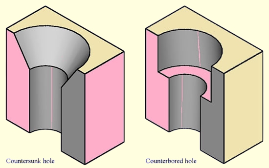
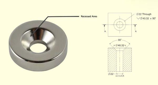
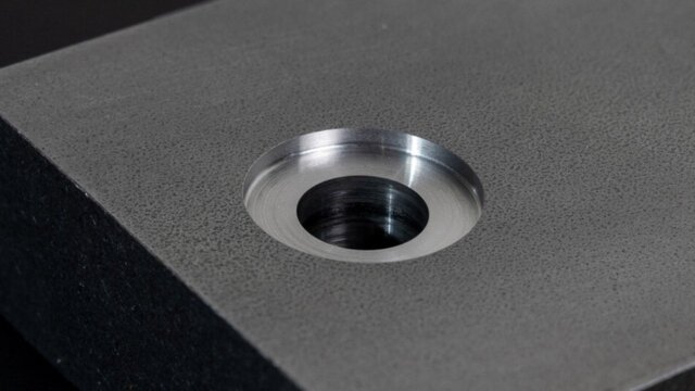
Une fraise est une cavité conique usinée autour d'un trou. Elle permet à une vis à tête plate ou ovale d'affleurer la surface du métal ou de s'y enfoncer légèrement. Cette conception est courante dans les applications où la surface extérieure doit être lisse, comme les boîtiers électroniques, les panneaux de commande ou les couvercles décoratifs.
Les angles de fraisage typiques sont 82°, 90° et 100°. La plupart des vis normalisées ISO utilisent un angle de 90°, tandis que certaines fixations aérospatiales ou américaines utilisent un angle de 82°. Il est essentiel de faire correspondre l'angle de la tête de la vis et celui du trou ; même un décalage de 1° peut entraîner une mauvaise assise, réduisant la surface de contact et les performances du couple.
Le fraisage offre un aspect élégant et sans raccord. Il empêche les têtes de vis de s'accrocher aux surfaces, réduit la résistance à l'air dans les boîtiers et protège les revêtements contre l'écaillage lors de la manipulation. Cependant, il n'est pas toujours idéal pour les matériaux fins.
Dans les tôles de moins de 2,0 mm d'épaisseur, un fraisage profond peut laisser trop peu de métal sous le cône - une situation connue sous le nom de faible épaisseur résiduelle. Dans ce cas, la vis peut déformer la tôle lors du serrage, réduisant ainsi la résistance du joint de 20 à 30%.
Pour maintenir la résistance, les ingénieurs laissent généralement au moins 30-40% de l'épaisseur originale de la tôle sous le fraisage. Par exemple, si la tôle a une épaisseur de 1,5 mm, le matériau restant sous le cône ne doit pas être inférieur à 0,5 mm.
Conseil de conception : Pour les panneaux esthétiques ou à faible charge, utilisez des fraises à 90° avec une profondeur contrôlée. Pour les pièces structurelles, envisager une autre méthode de fixation telle que les rivets ou les écrous à sertir.
Qu'est-ce qu'un trou de contre-perçage ?
Un lamage est une cavité cylindrique à fond plat destinée à recevoir la tête d'une vis à tête creuse ou à tête hexagonale. La principale différence avec une fraise est la géométrie - au lieu d'un cône, un lamage a des côtés droits et une profondeur définie.
Cette forme offre une plus grande surface d'assise et une meilleure répartition de la charge. Elle est idéale pour les pièces soumises à de fortes contraintes mécaniques, à des vibrations ou à des couples, telles que les supports de machine, les supports de moteur ou les panneaux structurels épais.
Dans un dessin technique, un lamage est représenté par le symbole "⌴" et défini par trois paramètres :
- Diamètre de l'alésage principal (pour la tête de la vis)
- La profondeur de l'évidement
- Le diamètre du trou pilote (pour la tige de la vis ou le jeu du filetage)
Les lamages sont pratiques pour les tôles d'une épaisseur supérieure à 3 mm, lorsque le matériau peut supporter un creux à fond plat sans déformation. En revanche, dans les tôles plus fines, cette caractéristique peut entraîner des déformations, en particulier lors du serrage ou de l'assemblage. soudage.
Pour réduire les risques, les fabricants ajoutent souvent des entretoises, des rondelles ou des inserts filetés plutôt que d'usiner un alésage profond.
Conseil de conception : Utiliser des contre-perçages pour les matériaux épais ou les joints à forte charge. Veiller à ce qu'il y ait au moins 1 mm d'espace libre sous la tête de la vis pour assurer un contact total lors du serrage.
Les principales différences en un coup d'œil
| Caractéristique | Compte-gouttes | Contre-trou |
|---|---|---|
| Forme | Conique | Cylindrique, à fond plat |
| Attache commune | Vis à tête plate / à tête ovale | Vis à tête cylindrique / à tête hexagonale |
| Effet visuel | Surface lisse et affleurante | Aspect mécanique encastré |
| Matériau adapté | Feuille mince ≤2 mm | Plaque épaisse ≥3 mm |
| Charge typique | Léger à modéré | Couple élevé / vibrations |
| Utilisation courante | Couvercles, panneaux, boîtiers | Cadres, supports, assemblages |
En bref :
- Choisir une fraise lorsque l'apparence et les surfaces affleurantes sont importantes.
- Choisir un lamage lorsque vous avez besoin d'un couple, d'une capacité de charge ou d'une résistance aux vibrations plus élevés.
Performances fonctionnelles et structurelles dans les applications de tôlerie
De petits choix géométriques peuvent affecter de manière significative les performances d'une pièce de tôlerie sous contrainte réelle. Voyons comment l'épaisseur, la charge et les vibrations déterminent le type de trou le plus performant.
Épaisseur du matériau et maintien de la résistance
Dans la conception des tôles, l'épaisseur détermine non seulement la résistance d'une pièce, mais aussi la quantité de matériau qui peut être enlevée en toute sécurité pour l'évidement. Un panneau mince peut sembler parfait avec une tête de vis affleurante, mais l'enlèvement d'une trop grande quantité de matière lors du fraisage peut réduire considérablement sa force portante.
Pour les tôles fines (≤2 mm), les fraisages profonds sont risqués. Le métal restant sous le cône devient fragile et peut se déformer sous l'effet du couple de serrage. Des essais en laboratoire sur des panneaux d'aluminium montrent que si l'épaisseur résiduelle tombe en dessous de 30% de la tôle d'origine, la résistance à la traction peut diminuer jusqu'à 25%, et la rupture par arrachement devient plus probable.
Les lamages, en revanche, nécessitent une cavité à fond plat. Cette conception ne fonctionne que lorsque la profondeur est suffisante pour maintenir l'épaisseur de la paroi et supporter la tête de la vis. C'est pourquoi les lamages sont généralement évités sur les matériaux minces - le processus enlève trop de métal et provoque souvent des bombements ou des déformations.
Pour les tôles plus épaisses (≥3 mm), les contre-perçages sont beaucoup plus performants. L'évidement plus profond crée un siège ferme pour la tête de la vis et maintient une structure de joint solide. Le matériau supplémentaire autour de l'évidement aide à absorber les contraintes et les vibrations.
Règle de conception : Utilisez des fraises pour les panneaux minces, mais réservez les lamages aux pièces suffisamment épaisses pour que la hauteur de la tête de la vis soit au moins égale à 1,5 fois la hauteur du matériau restant sous la cavité.
Résistance à la charge et aux vibrations
Les différents types de joints réagissent différemment aux contraintes mécaniques. Les vis à tête fraisée offrent des surfaces propres mais ont une capacité de charge limitée. L'interface conique concentre la pression sur un anneau de contact étroit, ce qui peut entraîner un desserrage sous l'effet des vibrations. C'est pourquoi les vis à tête fraisée conviennent mieux aux assemblages statiques et à faible charge. couverturesLes éléments de l'appareil, les boîtiers et les plaques d'accès ne sont pas soumis à des contraintes répétitives.
Les lamages, en revanche, offrent une surface d'appui plane et à contact total. Le couple et la pression de serrage sont ainsi répartis uniformément sur la tête de la vis. Sous l'effet de charges dynamiques élevées ou de vibrations, les joints lamellaires restent beaucoup plus stables. La surface d'appui plus large minimise les micro-mouvements et améliore la résistance à la fatigue, ce qui est essentiel dans les machines, cadresou les appareils où l'alignement doit rester précis dans le temps.
En guise d'illustration :
- Une vis M4 fraisée dans de l'aluminium de 1,5 mm peut supporter une force de serrage d'environ 300-400 N avant de se déformer.
- Une vis M4 percée dans une plaque d'acier de 4 mm peut supporter trois fois cette charge avec une perte minimale de rétention du couple.
Conseil : Lors de la conception d'équipements soumis à des mouvements ou à des chocs, préférez toujours les trous lamellaires combinés à des rondelles ou à des vis à tête creuse.
Contrôle de la planéité, de la tolérance et de l'alignement
Dans fabrication de tôles de précisionLa précision de la géométrie du trou affecte directement l'ajustement de l'assemblage et la finition de la surface. L'angle et la profondeur d'une fraise doivent correspondre parfaitement à la tête de la vis - même un petit écart peut entraîner une assise irrégulière ou fière de la vis. Pour les panneaux visibles, cela devient un défaut esthétique ; pour les pièces mécaniques, cela peut introduire des contraintes ou des écarts indésirables.
Le maintien d'une tolérance de ±0,05 mm sur la profondeur de la fraise permet d'obtenir un affleurement constant sur plusieurs pièces. L'utilisation d'une opération de chanfreinage à commande numérique, au lieu d'un perçage manuel, permet d'obtenir cette répétabilité.
Les lamages sont moins sensibles aux variations angulaires mais nécessitent un contrôle étroit de la profondeur pour s'assurer que les têtes de boulons sont complètement encastrées. Si le retrait est trop faible, la vis dépassera ; s'il est trop profond, la fixation risque de s'écraser avant d'appliquer une force de serrage suffisante. La tolérance recommandée est de ±0,10 mm pour la plupart des pièces industrielles.
Des évidements mal alignés ou inégaux peuvent également nuire à l'étanchéité, en particulier lorsqu'il s'agit de joints ou de plaques frontales. Un mauvais alignement entraîne une compression inégale, des fuites ou une usure prématurée.
Conseils pratiques : Modélisez toujours les évidements en CAO avec la géométrie réelle de la vis. Ne vous fiez pas uniquement aux angles théoriques : simulez l'ajustement de la tête, l'accumulation de revêtement et l'empilement des tolérances pour garantir la précision de la production.
Comportement thermique et sous contrainte
Outre les charges mécaniques, les pièces de tôle subissent des cycles thermiques et des contraintes résiduelles dues au soudage ou au revêtement. La section transversale plus fine d'un lamage peut se dilater ou se contracter plus rapidement que le matériau environnant, entraînant parfois des fissures dans le revêtement autour de l'évidement. Les trous alésés, plus profonds et plus épais, résistent à ce phénomène, mais peuvent retenir la chaleur pendant le soudage ou le durcissement de la poudre.
Pour les applications exposées à des variations de température - telles que les boîtiers extérieurs ou les carters de machines - il est essentiel de vérifier que le type d'évidement et la combinaison de fixations choisis peuvent tolérer la dilatation thermique sans se desserrer.
Fabrication et efficacité des coûts dans la production de tôle
Une conception parfaite n'a de valeur que si elle est efficace à produire. Voici comment les décisions en matière d'outillage, de temps de cycle et de finition influent sur le coût et la cohérence de la fabrication.
Exigences en matière d'outillage et d'usinage
Du point de vue de la production, la différence entre un lamage et un alésage n'est pas seulement géométrique, elle concerne également le nombre d'étapes et les outils nécessaires.
Un chanfrein est généralement une opération en une seule étape. Elle peut être réalisée à l'aide d'un foret combiné à une fraise, d'un outil de chanfreinage ou même d'un outil de poinçonnage doté d'une matrice conique. Cette opération est donc rapide et rentable pour la production de masse. Lorsqu'elle est intégrée dans des programmes de poinçonnage CNC ou à tourelle, l'opération n'ajoute que peu de temps de cycle, souvent moins de 3 secondes par trou.
Un lamage, en revanche, nécessite deux opérations : le perçage du trou de passage et l'usinage de l'évidement à fond plat. Sur les machines à commande numérique, ces opérations entraînent des changements d'outils et des temps de broche supplémentaires. Les forces de coupe sont également plus élevées car l'outil enlève un plus grand volume de matière. Cela se traduit par des vitesses d'avance plus lentes et une usure plus importante de l'outil, en particulier dans les métaux durs comme l'acier inoxydable.
Pour les grandes séries, ce temps supplémentaire s'additionne. Par exemple, l'usinage de 1 000 trous peut prendre environ une heure avec des fraises, mais près de trois heures avec des lamages, en fonction de l'épaisseur de la pièce et de la vitesse d'avance. C'est pourquoi de nombreux fabricants évitent les lamages, à moins qu'ils ne soient nécessaires pour la performance en termes de couple ou de charge.
Shop Insight : Dans une ligne de production de volume moyen, le passage du lamage au fraisage sur un boîtier en aluminium de 2 mm peut réduire le temps d'usinage total de 40%, sans affecter l'ajustement ou l'apparence.
Temps de cycle, précision et longévité des outils
Les outils à fraise ont tendance à durer plus longtemps. Ils coupent moins de matière et génèrent moins de chaleur. Les fraises en carbure peuvent souvent durer plus de 10 000 cycles avant d'être affûtées. Les fraises de lamage, quant à elles, subissent des contraintes plus importantes au niveau de la pointe de l'outil, en particulier lors de la découpe d'évidements à fond plat. Si le débit du liquide de refroidissement ou la vitesse d'avance ne sont pas optimisés, l'usure de l'outil s'accélère rapidement.
La précision est une autre préoccupation. Les lamages reposent principalement sur la précision de l'angle ; même en cas d'usure mineure, l'outil produit toujours des résultats acceptables. Les lamages exigent une planéité et la profondeur - toute variation affecte directement l'assise de la tête de la vis. Les outils émoussés laissent des traces de frottement ou des fonds irréguliers qui peuvent perturber l'alignement de l'assemblage.
Pour garantir la cohérence, les fabricants de gros volumes utilisent des centres d'usinage CNC à plusieurs axes ou des servopresses équipées de systèmes de rétroaction de la profondeur. Ces installations maintiennent une répétabilité de ±0,05 mm, même sur des milliers de cycles.
Conseil pratique : Lors de la production de pièces en vrac, il convient de normaliser les dimensions des fraises afin de réduire les changements d'outils. Pour les pièces nécessitant des lamages, combinez les opérations de perçage et de fraisage dans une seule installation CNC afin d'améliorer la précision et de minimiser la manipulation des fixations.
Compatibilité avec les finitions et les revêtements
Finition de surface est une autre raison pour laquelle le choix de l'évidement est important. Le revêtement par poudre, la peinture ou l'anodisation ajoutent 50 à 100 μm (microns) d'épaisseur par côté. Pour les fraisages, cette accumulation peut empêcher la tête de vis de s'asseoir à ras, la laissant légèrement au-dessus de la surface. Pour les lamages, les revêtements peuvent réduire le jeu autour de la tête de vis, entraînant des ajustements serrés ou même des interférences lors de l'assemblage.
Pour résoudre ce problème, les fabricants ajustent souvent la profondeur de l'évidement avant la finition. Une fraise peut être usinée à une profondeur de 0,1 à 0,2 mm supérieure à la profondeur nominale pour compenser l'accumulation de revêtement. Une autre solution consiste à masquer les trous critiques pendant le revêtement afin de préserver une géométrie précise.
Les arêtes vives dues à un mauvais usinage peuvent également provoquer des fissures ou un décollement du revêtement. Un léger ébavurage avant la finition permet de maintenir l'adhérence du revêtement et sa résistance à la corrosion, en particulier autour des trous encastrés où la peinture a tendance à s'amincir.
Note: Précisez toujours sur vos dessins si les trous sont "avant finition" ou "après finition". Cela permet d'éviter les conflits de dimensions lors de l'assemblage final.
Automatisation et optimisation des processus
Les usines de fabrication modernes intègrent de plus en plus souvent des outils de formage des évidements dans leurs systèmes de poinçonnage ou de laser. Les presses à tourelle perfectionnées peuvent créer des fraisages peu profonds directement au cours de la même opération de poinçonnage, ce qui élimine l'usinage secondaire. Ce formage hybride réduit la main-d'œuvre, raccourcit les délais et améliore la cohérence.
Pour les prototypes ou les lots de faible volume, l'usinage CNC reste l'option la plus flexible. Il permet un contrôle précis des ajustements de profondeur et de diamètre avant de passer à la production de masse. Cependant, lors de la conception pour la production, la simplicité l'emporte toujours :
- Moins de types d'évidements signifie moins d'outils à entretenir.
- L'uniformité des normes de vissage entre les lignes de produits réduit le temps de programmation et la nécessité de modifier les réglages.
Principe de fabrication : Choisissez le type d'évidement le plus simple qui réponde aux besoins fonctionnels. Chaque étape supplémentaire augmente les coûts, les manipulations et les variations de tolérance.
Lignes directrices et bonnes pratiques en matière de conception
Une bonne conception de la tôlerie permet d'équilibrer l'apparence, la résistance et la facilité de fabrication. Le choix entre une fraise et un lamage doit être guidé par des règles de conception claires, et non par des habitudes ou des préférences visuelles.
Pour les tôles fines (≤2 mm) :
- Utiliser des fraises peu profondes avec une profondeur contrôlée. Un angle de 90° est idéal pour la plupart des vis ISO à tête plate.
- Maintenir une épaisseur résiduelle d'au moins 30-40% sous l'évidement pour éviter les déformations.
- Pour les panneaux extrêmement fins, remplacez les fraises par des rivets, des goujons à sertir ou des écrous auto-agrippants. Ces derniers maintiennent la planéité de la surface et évitent d'affaiblir la tôle.
- Testez un prototype avant la production en série pour vous assurer que la tête de la vis est bien en place après le revêtement.
Pour les assemblages épais ou multicouches (≥3 mm) :
- Utiliser des contre-perçages lorsqu'un couple élevé ou une résistance aux vibrations sont nécessaires.
- Maintenir un espace d'au moins 1 mm entre le fond de l'évidement et la tête de la vis afin d'assurer un serrage constant.
- Évitez de placer les trous de contre-perçage à proximité de coudes, de soudures ou de zones gaufrées afin d'éviter toute déformation.
- Lorsque la vitesse d'assemblage est importante, il convient de normaliser les types de vis et les profondeurs d'évidement sur l'ensemble de votre conception.
Distance et espacement des bords :
Les trous doivent être distants d'au moins 2 fois l'épaisseur du matériau par rapport à toute arête ou ligne de pliage. Un espacement plus réduit augmente le risque de fissuration ou de déformation locale pendant le formage et le serrage.
Rappel sur l'ingénierie : La perfection esthétique est inutile si le joint s'affaiblit sous l'effet de la charge. Il faut toujours modéliser les contraintes, le revêtement et la séquence d'assemblage avant de finaliser le type de trou.
Les pièges les plus courants et comment les éviter
Même les concepteurs expérimentés négligent parfois de petits détails qui créent de gros problèmes de fabrication. Vous trouverez ci-dessous des erreurs fréquentes et leurs solutions :
| Erreur | Conséquence | Action préventive |
|---|---|---|
| Fraise trop profonde | La vis traverse une feuille mince | Fixer la limite de profondeur ; vérifier avec l'assemblage de l'échantillon |
| Contre-perçage sur matériau mince | Bombement ou fissure | Passer à la rondelle ou à la fixation par clinchage |
| Mauvaise adaptation de la tête de vis et de l'empreinte | Mauvaise assise, revêtement endommagé | Respecter la norme ISO pour les vis (par exemple, ISO 10642 pour les vis à tête plate à 90°) |
| Ignorer l'accumulation de revêtement | La vis s'enfonce ou se bloque | Augmenter la profondeur de 0,1 à 0,2 mm avant l'application de la couche. |
| Mauvais alignement dans les assemblages en plusieurs parties | Assemblage difficile ou tension sur les vis | Utiliser le perçage CNC ou la disposition des poinçons basée sur les données |
Conseil d'abrication : Si votre conception comprend les deux types d'évidement, indiquez-les clairement sur les dessins à l'aide de symboles standard (⌵ pour la fraise, ⌴ pour l'alésage). Cela permet d'éviter les erreurs d'usinage et les reprises.
Guide de référence rapide sur les fraises et les lamages
| Scénario d'application | Type recommandé | Raison |
|---|---|---|
| Couvercles, boîtiers ou panneaux d'accès minces | Compte-gouttes | Aspect propre et surface affleurante |
| Cadres de machines, supports ou joints porteurs | Contre-trou | Couple élevé et résistance aux vibrations |
| Surfaces esthétiques ou parties visibles | Compte-gouttes | Aspect lisse, perturbation minimale du revêtement |
| Assemblages soumis à des mouvements ou à des contraintes | Contre-trou | Contact total et serrage stable |
| Pièces minces nécessitant un entretien fréquent | Fixations auto-agrippantes ou à rivets | Rapide, fiable et sans affaiblissement de la feuille |
Logique de décision :
- Si l'aspect et la faible charge sont importants → choisissez une fraise.
- Si le couple, la rigidité ou la résistance aux vibrations sont importants → choisissez un lamage.
- Si la feuille est trop fine pour l'un ou l'autre → utiliser une alternative de fixation mécanique.
Conclusion
La fraise et le lamage se ressemblent, mais ils ont des fonctions différentes. Une fraise offre une finition lisse et professionnelle sur des matériaux fins, parfaite pour les surfaces visibles et les applications à faible contrainte. Un lamage offre une solide résistance au couple et une durabilité pour les pièces plus épaisses et porteuses.
Les meilleures conceptions commencent par une compréhension claire de ces compromis. En tenant compte à la fois de l'épaisseur, de la contrainte et du coût de production, les ingénieurs peuvent créer des assemblages de tôle qui sont non seulement précis, mais aussi efficaces et visuellement raffinés.
Quel type de trou convient à votre pièce de tôle ? Notre équipe d'ingénieurs peut vous aider à choisir le modèle, la profondeur et la tolérance adaptés à votre matériau et à votre méthode de production. Téléchargez vos fichiers CAO pour un examen DFM gratuit - nous analyserons la fabricabilité, proposerons des optimisations et veillerons à ce que vos pièces soient prêtes pour la production.
Hey, je suis Kevin Lee

Au cours des dix dernières années, j'ai été immergé dans diverses formes de fabrication de tôles, partageant ici des idées intéressantes tirées de mes expériences dans divers ateliers.
Prendre contact
Kevin Lee
J'ai plus de dix ans d'expérience professionnelle dans la fabrication de tôles, avec une spécialisation dans la découpe au laser, le pliage, le soudage et les techniques de traitement de surface. En tant que directeur technique chez Shengen, je m'engage à résoudre des problèmes de fabrication complexes et à favoriser l'innovation et la qualité dans chaque projet.
Ressources connexes

Acier inoxydable résistant aux empreintes digitales : comment fonctionne-t-il et comment le choisir ?

OEM ou fabrication en sous-traitance : Comment choisir le bon modèle pour votre projet

Coûts d'installation et coûts unitaires dans la fabrication de tôles
