Lorsque les trous, les courbes ou les gaufrages sont trop proches les uns des autres, la qualité du formage diminue rapidement. Le métal ne peut pas s'étirer uniformément, ce qui entraîne des fissures, des plis ou des formes déformées. Ces problèmes augmentent les rebuts, usent les outils plus rapidement et ralentissent la production. La plupart du temps, la cause est un mauvais espacement au stade de la conception.
Un formage fiable commence par un espacement adéquat. Le maintien d'une distance suffisante entre les caractéristiques permet au métal de s'écouler librement. Il réduit les contraintes et contribue à maintenir une géométrie cohérente de la pièce. Un bon espacement protège également l'outillage, améliore la répétabilité et réduit les coûts de production.
Concevoir avec un espacement correct fait la différence entre un processus fluide et un processus risqué. Voyons comment fonctionne la proximité et pourquoi elle est importante dans chaque conception de tôle.

Principes de base de la proximité des caractéristiques dans la conception des tôles
La proximité des caractéristiques est la distance entre les caractéristiques telles que les trous, les courbes, les gaufrages ou les découpes sur une pièce de tôle. Cette distance influe directement sur le comportement du matériau pendant le formage. Lorsque les caractéristiques sont trop proches les unes des autres, les contraintes s'accumulent, ce qui entraîne des fissures ou un étirement inégal.
Définition et fonction
La proximité des caractéristiques contrôle la stabilité mécanique. Un espacement adéquat assure la solidité de la pièce et réduit les déformations. Par exemple, si deux trous sont trop proches d'un plierLes deux tirent sur la même zone de matériau pendant le formage. Cela peut entraîner une déchirure ou un allongement autour des trous. Avec un espacement correct, chaque étape du formage se déroule sans interférence.
Influence des propriétés des matériaux
Les propriétés des matériaux déterminent l'espacement des caractéristiques.
- Ductilité: Les métaux plus souples comme l'aluminium peuvent s'étirer davantage, ce qui permet des agencements plus serrés. L'acier inoxydable est plus rigide et moins ductile, et nécessite donc un espacement plus important.
- Sens du grain : Le sens du grain du métal influe sur la façon dont il s'étire. Les éléments placés le long du grain peuvent se fissurer plus rapidement. Les caractéristiques placées le long du grain peuvent se fissurer plus rapidement, tandis que les caractéristiques placées en travers du grain répartissent les contraintes de manière plus uniforme.
- Épaisseur: Les tôles plus épaisses résistent mieux à la flexion et à l'étirement. Elles doivent être plus espacées pour éviter la concentration des contraintes.
| Matériel | Ductilité | Espacement recommandé entre les trous et les coudes | Notes |
|---|---|---|---|
| Aluminium (5052/6061) | Haut | 1,5t - 2t | Permet des mises en page plus serrées |
| Acier doux (SPCC) | Moyen | 1,5t - 2,5t | Fonctionne pour les applications générales |
| Acier inoxydable (304/316) | Faible | 2t - 3t | Nécessité d'un espacement et de rayons plus larges |
Types de caractéristiques communes et leur interaction
Une fois que vous avez compris ce que signifie la proximité, l'étape suivante consiste à comprendre comment les différentes caractéristiques interagissent pendant la formation. Chaque type d'élément gère les contraintes différemment, de sorte que les règles d'espacement changent en fonction de la géométrie.
Trous près des coudes
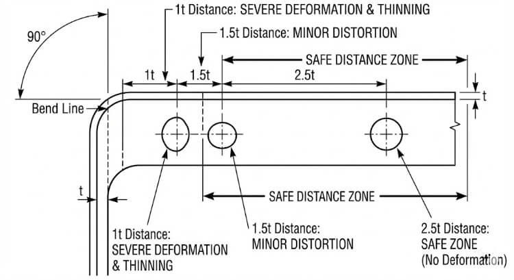
Les trous placés près des plis se déforment souvent. Lorsque la tôle se plie, la zone autour de la ligne de pliage s'étire, tirant le matériau près du trou. Cela peut provoquer des fissures ou modifier la forme du trou.
Pour éviter cela, maintenez les trous à une distance d'au moins 1,5 à 2,5 tonnes de la ligne de pliage. Pour l'acier inoxydable ou les matériaux à haute résistance, cette distance doit être portée à 3 tonnes. La directive SAE J2550 soutient ces valeurs, montrant qu'elles permettent de maintenir la forme des trous pendant les coudes à 90°.
Gaufrages et persiennes près des bords
Gaufrages et persiennes rendent la tôle plus résistante mais limitent le flux de métal. S'ils se trouvent trop près d'un bord, les tensions s'accumulent, entraînant des fissures ou des déformations du bord.
Respecter une distance d'au moins 3 t par rapport au bord le plus proche. Pour les gaufrages plus profonds ou les persiennes, prolongez jusqu'à 4 t. Cet espacement permet aux bords de rester plats et de ne pas se déformer après le formage.
Onglets et découpes formés
Les onglets et les découpes modifient la façon dont le matériau se déplace pendant le pliage. Lorsqu'elles sont placées trop près les unes des autres, la feuille s'étire de manière irrégulière. Il en résulte une mauvaise qualité de pliage et des angles incohérents.
Les languettes doivent être distantes d'au moins 1 t et de 1,5 t des trous ou des coudes. Cela permet d'équilibrer les contraintes et d'assurer un formage en douceur pendant la production et l'assemblage.
Contraintes de géométrie de conception et leurs effets
La géométrie des caractéristiques affecte la façon dont les contraintes se déplacent dans le métal pendant le formage. Le respect de règles d'espacement appropriées aide les concepteurs à prévoir le comportement du formage avec plus de précision.
Lignes directrices sur les distances minimales
Les normes industrielles expriment souvent l'espacement comme un multiple de l'épaisseur de la tôle (t). Le tableau ci-dessous présente des recommandations générales :
| Type de processus | Relation avec les caractéristiques | Distance recommandée | commentaires |
|---|---|---|---|
| Pliant | Du trou à la ligne de pliage | 1,5t - 2,5t | Règle de conception commune |
| Découpage des bords | Du trou au bord | ≥ 1.0t | Prévient la déchirure des bords |
| Gaufrage/ouverture jusqu'au bord | 3t - 4t | Maintien de la planéité | |
| Dessin en profondeur | D'un article à l'autre | ≥ 5t | Évite les problèmes d'amincissement |
| Monnayage | D'un article à l'autre | ≥ 2t | Réduit la tension de l'outil |
Il s'agit de points de départ. L'espacement exact dépend de facteurs tels que la résistance du matériau, l'angle de pliage et la précision de l'outillage.
Rayon de courbure et interaction des caractéristiques
L'intérieur rayon de courbure influe également sur la proximité des caractéristiques. Un rayon plus petit augmente les contraintes au niveau de la courbure. Si un trou est trop proche, il peut se fissurer ou se déformer.
Les trous doivent être éloignés du coude d'au moins 1,5 fois le rayon de courbure. Pour les matériaux plus durs comme l'acier inoxydable, augmentez le rayon à 2×. Des rayons plus grands permettent de répartir plus uniformément les contraintes et d'améliorer la cohérence des pièces.
Lorsque l'espacement et le rayon sont bien équilibrés, le matériau se plie en douceur, ce qui réduit les risques de blessures. dos d'âneLes produits de l'industrie de l'acier peuvent être utilisés pour la fabrication d'emballages, le gauchissement et la reprise de travaux.
Considérations relatives à l'outillage et au processus
La façon dont les matrices, les poinçons et les outils de presse interagissent limite directement la distance à laquelle les caractéristiques peuvent être placées. Un mauvais accès à l'outil ou des interférences peuvent endommager même la pièce la mieux conçue.
Dégagement de la matrice et accès à l'outil
Chaque poinçon et chaque matrice ont besoin de suffisamment d'espace pour fonctionner en toute sécurité. Lorsque les trous, les onglets ou les gaufrages sont trop proches les uns des autres, les trajectoires des outils peuvent se chevaucher. Cela peut entraîner des rayures, des bavures ou la casse de l'outil.
Pour éviter ces problèmes :
- Maintenez une distance d'au moins 1t entre les éléments qui partagent le même chemin d'outil.
- Pour les matrices composées ou progressives, augmentez l'écart à 2t-3t afin d'éviter le chevauchement entre les courses.
- Pour les formes profondes ou à plusieurs étapes, effectuez une simulation de l'outillage avant de couper l'acier de l'outil.
L'accès aux outils est essentiel dans les opérations de presses plieuses et de matrices progressives. Dans une presse plieuse, un espacement serré peut empêcher le nez du poinçon de s'insérer correctement entre les zones formées. Dans une matrice progressive, différents poinçons peuvent frapper des régions qui se chevauchent si la disposition est trop compacte. La validation par CAO 3D permet de détecter ces problèmes à un stade précoce et d'éviter des retouches coûteuses de l'outillage.
Séquence de formage et retour élastique
L'ordre dans lequel les étapes de formage sont exécutées a une incidence sur la précision finale. Lorsque les caractéristiques sont proches les unes des autres, le pliage d'une zone peut déformer l'autre. Par exemple, la formation d'une bride à proximité d'une persienne peut aplatir ou décaler la hauteur de la persienne.
Suivre une séquence de formation logique :
- Former d'abord des formes profondes ou des gaufrages.
- Effectuez ensuite les flexions.
- Terminer par le parage et le perçage.
Cette séquence réduit le transfert de contraintes entre les éléments.
Le retour élastique est un autre facteur à surveiller. Après le pliage, la tôle a tendance à revenir vers son état plat. Plus les caractéristiques sont proches, plus l'effet du retour élastique sur les zones voisines est important.
Les moyens de contrôler le retour élastique sont les suivants :
- Augmentation du rayon de courbure.
- L'ajout d'une étape de redressement ou de monnayage pour stabiliser la géométrie.
- Ajuster l'espacement des éléments pour réduire l'interaction entre les zones.
L'utilisation de la simulation pour prévoir et compenser le retour élastique permet de maintenir des angles stables et une géométrie propre dans les pièces de production.
Méthodes de simulation et de validation
Avant la production en série, des simulations et des tests confirment que les règles d'espacement sont sûres. Ces étapes de validation permettent de faire le lien entre la théorie de la conception et le comportement réel du formage.
Analyse par éléments finis (FEA) dans les essais de proximité
L'analyse par éléments finis permet aux ingénieurs de voir comment les contraintes et les déformations se déplacent dans le métal pendant le formage. Lorsque les caractéristiques sont trop proches les unes des autres, des zones de forte contrainte se forment, généralement aux mêmes endroits où des fissures ou des plis se forment par la suite.
Des logiciels tels qu'AutoForm, ABAQUS et ANSYS peuvent modéliser ces effets avec précision. Ils montrent comment les changements d'espacement, de rayon de courbure ou de type de matériau influencent l'amincissement et le retour élastique.
Les principaux résultats de l'AEF sont les suivants :
- Cartes de distribution de l'épaisseur : indiquent les endroits où le matériau peut s'amincir excessivement.
- Diagrammes de limite de formation (FLD) indiquent les niveaux de déformation à partir desquels la déchirure se produit.
- Courbes de niveau de contrainte : mettre en évidence les zones soumises à de fortes contraintes, à proximité des trous ou des gaufrages.

Essais et ajustements du prototype
Même avec des simulations détaillées, des essais de formage réels sont toujours nécessaires. Les prototypes révèlent comment le matériau réel se comporte dans les conditions réelles de la presse, y compris le frottement, l'usure de l'outil et la lubrification.
Lors des essais, les ingénieurs vérifient :
- Précision de la forme et de la position des trous.
- Cohérence de l'angle de courbure et du rayon.
- L'amincissement de la surface ou la formation de plis à proximité des éléments formés.
Si des problèmes apparaissent, l'espacement ou le rayon est ajusté. Un processus typique combine les résultats de l'analyse par éléments finis et les données d'essais physiques. Une fois que les deux sont alignés, l'agencement est prêt pour la production complète.
Stratégies d'optimisation de la conception
Après avoir confirmé la sécurité de l'espacement, l'étape suivante consiste à optimiser l'agencement pour des raisons de performance et d'esthétique.
Équilibrer l'esthétique et la fabricabilité
Les concepteurs réduisent parfois l'espacement pour obtenir des présentations compactes ou visuellement alignées. Si l'aspect est plus net, cela peut entraîner des problèmes de formage tels que des déformations ou des fissures.
La meilleure approche consiste à procéder à des ajustements sélectifs. L'augmentation de l'espacement, ne serait-ce que de 0,5 t dans les zones clés, peut éviter des problèmes tout en maintenant l'aspect général inchangé. L'implication précoce des ingénieurs en outillage permet de trouver ces points d'équilibre avant le début de la production.
Un travail d'équipe étroit entre la conception et la fabrication garantit le maintien de l'esthétique et de l'efficacité.
Normalisation et bibliothèques de connaissances
La création de bibliothèques internes de règles de proximité améliore la cohérence. Ces bases de données enregistrent des ratios éprouvés pour chaque matériau et processus, ainsi que des notes tirées de l'expérience de la production.
| Matériel | Trou-Coude | Bordure en relief | Tab-Tab | Source |
|---|---|---|---|---|
| Aluminium 5052 | 1,5t-2t | 3t | 1t | Données de test internes |
| Acier doux SPCC | 2t | 3.5t | 1.5t | Retour d'information sur la production |
| Inox 304 | 2,5t-3t | 4t | 1.5t | Validation de l'outillage |
Ces références permettent de réduire le temps de conception, d'éviter les erreurs répétées et de maintenir une qualité de formage constante d'un projet à l'autre. Au fil du temps, cette base de connaissances partagées permet d'améliorer les conceptions, de réduire les coûts d'outillage et de faciliter la production.
Erreurs de conception courantes et comment les éviter
Même les concepteurs les plus compétents négligent parfois les règles d'espacement. Ces erreurs peuvent sembler mineures sur le dessin, mais elles sont souvent à l'origine de défauts de formage ultérieurs. Leur identification précoce permet d'éviter le gaspillage, l'usure des outils et les retards de production.
Ignorer le sens du grain et le flux de matière
Une erreur fréquente consiste à oublier le sens du grain du matériau. Lors du laminage, les grains du métal s'alignent dans une direction, ce qui influe sur l'étirement et le pliage de la tôle.
Lorsque des trous, des fentes ou des gaufrages sont placés le long du fil, des fissures se forment souvent lors du pliage ou de l'étirage. Le métal s'étire plus facilement le long du grain mais résiste à l'étirement transversal, ce qui crée des zones de faiblesse. Ce problème est plus marqué dans l'acier inoxydable et les alliages à haute résistance dont la ductilité est faible.
Meilleures pratiques :
- Dans la mesure du possible, placer les trous et les fentes perpendiculairement au sens du grain.
- Faites pivoter les éléments profonds, tels que les persiennes ou les coupes étirées, de manière à ce qu'ils soient en travers du grain.
- Pour les pièces dont les limites de formage sont étroites, demandez des certificats d'usine indiquant l'orientation du grain avant de planifier l'agencement.
Le contrôle de la direction du grain permet à la tôle de s'étirer uniformément, ce qui améliore la précision, l'état de surface et la résistance à la fatigue.
Dispositions surchargées
Une autre erreur consiste à faire entrer trop de caractéristiques dans un espace réduit pour économiser du matériau ou rendre la conception plus compacte. L'encombrement limite le flux de métal pendant le formage, ce qui augmente le risque de déformation, de déchirure ou de distorsion.
Par exemple, dans les pièces de support, les trous placés trop près des courbes peuvent s'allonger lorsque la bride se forme. Les persiennes positionnées trop serrées peuvent se chevaucher pendant le pressage, laissant des marques sur la surface ou même endommageant la matrice.
Stratégies de prévention :
- Appliquer des ratios d'espacement en fonction de l'épaisseur de la tôle (t) et du type de formage.
- Utilisez la simulation FEA ou des essais d'échantillons pour tester des agencements complexes.
- Inclure un examen de la fabricabilité avec les ingénieurs chargés de l'outillage avant de valider la conception.
Une disposition surchargée peut sembler efficace en CAO, mais elle augmente souvent les retouches, les temps d'inspection et les rebuts. Les conceptions équilibrées produisent une meilleure qualité et des performances de formage plus stables.
Conclusion
Le respect des règles d'espacement est l'un des moyens les plus efficaces de garantir la stabilité du formage de la tôle. Un espacement adéquat permet un écoulement fluide du matériau, évite les fissures et maintient la précision des dimensions. Il protège également les outils et réduit les rebuts, les temps de préparation et les interruptions de production.
La validation précoce par la simulation et les essais de prototypes permet de s'assurer que la conception fonctionnera bien dans des conditions réelles. Lorsque les équipes de conception, d'outillage et de production travaillent ensemble, elles peuvent identifier rapidement les risques liés à l'espacement et obtenir des résultats de formage cohérents avec moins de surprises.
Prêt à renforcer votre conception de la tôlerie ?
Notre équipe d'ingénieurs peut vous aider à vérifier la faisabilité de vos plans. Envoyez vos dessins ou modèles 3DNous vérifierons les limites d'espacement, simulerons les étapes de formage et recommanderons des améliorations avant le début de l'outillage.
FAQ
Que se passe-t-il si un trou est trop proche d'une ligne de pliage ?
Le trou peut s'étirer, se déformer ou se fissurer pendant le formage parce que le matériau autour du coude se déforme de manière inégale. Le respect d'un jeu de 1,5 à 2,5 tonnes permet de conserver la forme et la solidité de l'ouvrage.
Comment trouver un espacement sûr pour un nouveau matériau ?
Commencez par des ratios standard basés sur l'épaisseur de la tôle et la résistance à la traction, puis confirmez les résultats par des simulations et des essais de prototypes.
Les règles d'espacement changent-elles entre les pièces découpées au laser et les pièces poinçonnées ?
Oui. Les pièces poinçonnées nécessitent un espacement plus important pour résister aux forces d'impact et éviter les bavures ou les déformations. Les pièces découpées au laser peuvent être plus espacées car elles n'impliquent aucune contrainte mécanique.
Hey, je suis Kevin Lee

Au cours des dix dernières années, j'ai été immergé dans diverses formes de fabrication de tôles, partageant ici des idées intéressantes tirées de mes expériences dans divers ateliers.
Prendre contact
Kevin Lee
J'ai plus de dix ans d'expérience professionnelle dans la fabrication de tôles, avec une spécialisation dans la découpe au laser, le pliage, le soudage et les techniques de traitement de surface. En tant que directeur technique chez Shengen, je m'engage à résoudre des problèmes de fabrication complexes et à favoriser l'innovation et la qualité dans chaque projet.
Ressources connexes

Poinçonnage ou découpe laser : Coût, vitesse et compromis DFM

Usinage d'angle : Ce qui détermine le coût et la qualité des pièces

Acier inoxydable résistant aux empreintes digitales : comment fonctionne-t-il et comment le choisir ?
