When your sheet metal parts don’t bend as planned, it can throw off everything—hole alignment, dimensions, and final assembly. That usually happens because the K factor was off. It impacts how flat patterns are calculated and how the finished part turns out. If you’re not using the right K factor, you’ll end up with bent parts that don’t match your model or drawing.
The K Factor is a number that tells you where the stretch happens during bending. It shows how far into the sheet the neutral axis moves. When you bend a sheet, the outside stretches, and the inside compresses. The K Factor sits in between. It helps you calculate how much material you need for accurate flat patterns. If the K Factor is wrong, your part won’t bend the way you planned.
If you want a better fit, tighter tolerances, and fewer surprises, you need to pay attention to this number.
What is the K Factor in Sheet Metal?
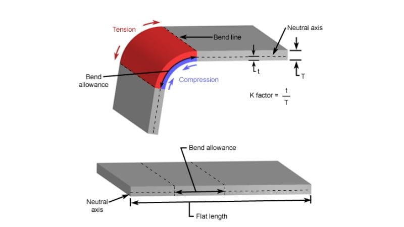
The K factor is the ratio that shows where the neutral axis sits within the thickness of the metal during bending. When metal bends, the top side compresses, and the bottom side stretches. Somewhere between these two forces is a line that doesn’t change in length. This is the neutral axis.
The K Factor expresses the ratio of the Neutral Axis’ Offset (t) to the Material Thickness (MT). This calculation is vital as it influences how the sheet metal is handled, bent, and cut to meet precise specifications. The image below demonstrates how the bend compresses at the top and stretches at the bottom.

The Science Behind Sheet Metal K Factor
When you bend metal, the inner surface gets compressed. The outer surface stretches. Somewhere in between is a line that doesn’t change length. That line is the neutral axis.
The K factor tells you where that line sits as a fraction of the total thickness. A K factor of 0.5 means it’s in the middle. A K factor of 0.3 means it’s closer to the inside.
The exact position depends on the material, bend radius, and bending method.
How Does the K Factor Affect Sheet Metal Bending?
If your K factor is wrong, your flat pattern will be wrong. That leads to holes in the wrong spots, edges that don’t line up, or parts that don’t fit.
A low K factor makes the flat pattern longer. A high K factor shortens it. Getting this number right helps you get precise parts without rework.
The Relationship Between the K Factor and Neutral Axis
The neutral axis moves depending on how the metal bends. Tighter bends and harder metals shift it closer to the inside.
The K factor shows how far that axis is from the inner surface. If you know the neutral axis location, you can calculate bend allowance and bend deduction. That helps you design parts that match what comes off the press brake.
K Factor Calculator
Knowing the correct K factor helps you get accurate flat patterns and reduces trial-and-error in fabrication. Let’s break down how it’s calculated and what it reveals about your material.
How to Calculate the K Factor?
You can calculate the K factor using a formula that includes bend allowance, bend angle, material thickness, and inside radius. The equation is:
K = (180° × BA) / (π × θ × T) − (Ri / T)
Where:
- K is the K factor
- BA is the bend allowance
- θ is the bend angle in degrees
- T is the material thickness
- Ri is the inside bend radius
Once you have these values, plug them into the formula. This will give you the K factor, which tells you how far the neutral axis lies from the inner bend surface, as a fraction of the sheet thickness.
To find the actual position of the neutral axis, multiply the K factor by the material thickness:
t = K × T
K-Factor Calculator
K Factor Formula and Geometry Explained
K factor comes from how metal behaves when bent into an arc. The bend forms a circular shape with a specific radius. While the outer side stretches and the inner side compresses, the neutral axis stays the same length.
The arc length of the neutral axis is used to calculate bend allowance. The position of this axis inside the material affects how much longer or shorter the flat piece needs to be. That’s why the K factor is built into bend allowance and bend deduction formulas.
Neutral Axis Shift: What It Tells You About Material Behavior
If the bend is tight, the neutral axis shifts closer to the inside surface. If the bend is larger or the material is softer, the axis sits more toward the center. This shift reflects how the material handles tension and compression.
Harder materials and tighter bends create more shifts. Softer materials or large bend radii reduce it. Watching this behavior helps you predict how the material will react during bending.
Sheet Metal K-Factor Chart
A K-Factor Chart provides reference values, usually between 0 and 0.5, for common materials like steel, aluminum, and stainless steel. It’s a starting point for general fabrication, indicating typical deformation degrees for various thicknesses and materials.
| Radius | Soft / Aluminum | Medium / Steel | Hard / Stainless Steel |
|---|---|---|---|
| Air Bending | |||
| 0 - Mt. | 0.33 | 0.38 | 0.4 |
| Mt. - 3*Mt. | 0.4 | 0.43 | 0.45 |
| 3*Mt. - >3*Mt. | 0.5 | 0.5 | 0.5 |
| Bottom Bending | |||
| 0 - Mt. | 0.42 | 0.44 | 0.46 |
| Mt. - 3*Mt. | 0.46 | 0.47 | 0.48 |
| 3*Mt. - >3*Mt. | 0.5 | 0.5 | 0.5 |
| Coining | |||
| 0 - Mt. | 0.38 | 0.41 | 0.44 |
| Mt. - 3*Mt. | 0.44 | 0.46 | 0.47 |
| 3*Mt. - >3*Mt. | 0.5 | 0.5 | 0.5 |
Design and Engineering Considerations
To get precise parts, engineers need to apply the right K factor at the design stage. This avoids production errors and wasted material.
How to Select the Right K Factor for CAD Models?
Start by checking the bending method. Air bending, bottoming, and coining all need different K values. Then, consider material type and thickness. Use a tested K factor from past projects or run a bend test on your setup.
If you’re unsure, begin with 0.4 as a baseline for air bending. Then, fine-tune the value based on bend results and material feedback.
Using K Factor in Sheet Metal Design Software
Most CAD programs have built-in tools for sheet metal design. In SolidWorks, you can set the K factor directly in the sheet metal feature. Fusion 360 also lets you enter the K factor when defining bend rules.
Use the K factor to calculate bend allowance automatically. This helps you flatten parts in your model while keeping the final dimensions accurate. Make sure the value matches your real-world bending setup.
Mistakes to Avoid When Using Incorrect K Factor Values
A wrong K factor causes errors in flat patterns. This leads to bends that miss target dimensions. Holes may end up misaligned. Tabs may not fit.
Avoid copying K factors from unrelated projects. Don’t rely on default values unless they match your process. Skipping test bends or ignoring the real material behavior can cost time and money later.
Practical Methods to Determine the K Factor
The most reliable K factor comes from your shop floor. These hands-on methods help you match design with real results.
Empirical Testing: Measuring the K Factor in Your Workshop
Cut a sample strip of your sheet metal. Mark a known distance across it. Then, bend it to the angle and radius you plan to use. After bending, measure the outside arc and compare it to your original length.
Use the actual bend results to calculate where the neutral axis fell. From that, you can determine your real-world K factor. This gives better accuracy than using rough estimates.
Using Bend Test Coupons to Fine-Tune the K Factor
A bend coupon is a small piece of sheet metal used just for testing. It lets you check bend quality and accuracy without risking full parts.
Bend several coupons with the same settings you plan to use in production. Measure them and adjust your K factor in the CAD model to match the real bend outcome. This is the fastest way to dial in flat patterns.
Reference Tables and Industry Standards
If you can’t run tests, use a standard K-factor chart as a starting point. Many tooling vendors, press brake manuals, or industry groups publish charts based on material, bend radius, and tooling type.
These values are close but not always exact. Use them as a guide, then refine them with testing. Standards like DIN or ANSI may also include suggested K factors for specific setups.
Conclusion
The K factor is a small number that makes a big difference in sheet metal bending. It tells you where the neutral axis sits and helps you calculate accurate flat patterns. Using the right K factor improves part fit, reduces waste, and avoids costly rework. It changes based on material, thickness, bending method, and tooling. Always test and adjust for the best results in real-world fabrication.
Need help with custom sheet metal parts or accurate flat pattern design? Reach out to our engineering team today—we’ll make sure your bends are right the first time.
Hey, I'm Kevin Lee

For the past 10 years, I’ve been immersed in various forms of sheet metal fabrication, sharing cool insights here from my experiences across diverse workshops.
Get in touch
Kevin Lee
I have over ten years of professional experience in sheet metal fabrication, specializing in laser cutting, bending, welding, and surface treatment techniques. As the Technical Director at Shengen, I am committed to solving complex manufacturing challenges and driving innovation and quality in each project.
Related Resource

Fingerprint Resistant Stainless Steel: How It Works,and How to Choose


