A single hole might seem minor, yet in sheet-metal fabrication it can decide the entire production pace. One misplaced or undersized hole can distort a bend, damage a tool, or cause assembly delays. In contrast, a well-designed hole shortens machine time, keeps parts aligned, and improves overall yield.
Most fabrication issues start long before cutting begins—inside the CAD model. By setting proper hole dimensions, spacing, and tolerances early, engineers make parts easier to produce and reduce rework later.
This article explores the fundamental principles underlying sheet-metal hole design, explaining how geometry, material behavior, and process limitations interact to achieve both quality and efficiency.
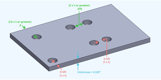
Hole-to-Thickness Ratio Guidelines for Sheet-Metal Design
A simple yet powerful rule governs most projects:
💡 Design Tip: Keep the hole diameter at least equal to the material thickness.
For example, in a 1.5 mm aluminum sheet, the smallest safe hole is Ø 1.5 mm. Going smaller dramatically increases punching pressure, creates more burrs, and reduces punch life. Harder materials, such as stainless steel, require larger ratios—approximately 1.5 times the thickness—to prevent cracking or tool deflection.
| Material Type | Typical Thickness (mm) | Minimum Hole Ø (mm) | Practical Notes |
|---|---|---|---|
| Aluminum | 1.0 – 3.0 | ≥ thickness | Clean edges, low tonnage |
| Mild Steel | 1.0 – 4.0 | ≥ 1.2 × thickness | Balanced forming behavior |
| Stainless Steel | 0.8 – 3.0 | ≥ 1.5 × thickness | Avoids cracking, extends tool life |
| Copper / Brass | 1.0 – 2.5 | ≥ thickness | Requires sharp tooling |
Even small deviations can increase costs: punching holes 20% smaller than recommended may reduce punch lifespan by 40%. For decorative or ventilation patterns that require small holes, laser cutting is preferable—but expect slower cycle times and increased inspection effort.
Hole Placement & Edge-Distance Guidelines
Hole position influences both appearance and forming reliability. If holes sit too close to an edge or bend, the metal stretches unevenly and may crack under pressure.
| Feature | Minimum Distance | Purpose |
|---|---|---|
| Hole → Edge | ≥ 1.5 × thickness | Prevent tear-out |
| Hole → Bend line | ≥ 2 × thickness | Avoid distortion |
| Hole → Hole | ≥ 2 × hole diameter | Maintain stiffness |
⚠️ Common Error: Placing mounting holes less than 2 mm from a bend on a 1 mm sheet often causes tearing during forming.
Fix: Shift holes outward by 2 – 3 mm or add relief cuts near the bend line.
When tight layouts are unavoidable—such as hinge flanges—secondary drilling after bending ensures cleaner results. In one production case, simply moving the hole pattern 2 mm farther from the bend line cut resulted in a 30% reduction in tearing defects, saving several hours of manual rework.
Tolerance Planning for Cost-Effective Fabrication
Precision always costs time. Setting realistic tolerances ensures both accuracy and affordability in the production process.
| Hole Function | Practical Tolerance (mm) | Fabrication Method |
|---|---|---|
| General mounting holes | ± 0.15 | Punching or laser cutting |
| Hardware holes (PEM nuts / rivets) | ± 0.08 | Clean edges required |
| Locating / alignment holes | ± 0.03 | Secondary reaming if needed |
Use the tightest tolerance only where necessary to ensure optimal function. Relaxing non-critical holes can reduce total inspection time and tool wear by 10 – 15 %. The best practice is to tag hole type and tolerance in the CAD file—so fabricators instantly know which ones require precision and which do not.
💡 Design Tip: Mark holes as clearance, tap, or press-fit directly in your drawing. This single note saves multiple emails during production.
From CAD to Real-World Fabrication
A drawing that looks perfect on-screen can fail in real life. For example, a row of M3 holes along a flange may overlap the bend radius once the sheet is formed, distorting the alignment. Adjusting the pattern outward by just 1 mm prevents damage and maintains a smooth bend.
Before releasing the drawings, unfold the flat pattern and verify the hole spacing relative to the edges and bends. This quick check prevents scrap and late-stage drilling.
⚙️ Quick Rule: Review smallest hole + nearest bend distance ≥ 2 × sheet thickness before approval.
Every millimeter of foresight in CAD translates into minutes saved on the shop floor.
Material Behavior and Hole Quality
Different metals react differently to cutting and forming forces. Aluminum cuts cleanly with low tonnage. Stainless steel needs higher pressure and sharper punches. Galvanized steel may chip its zinc coating around edges unless clearance is increased by + 0.1 mm. Copper and brass are soft but sticky, requiring good lubrication and tool cleaning.
As the thickness exceeds 3 mm, the burr height grows quickly. Always plan for deburring or chamfering in finishing notes. Failing to follow this step may result in coating defects, poor hardware seating, or operator injuries during the assembly process.
⚠️ Common Error: Assuming burrs will “burn off” during powder coating often results in coating bubbles or misfit hardware later.
💡 Design Tip: Include “Deburr all edges and holes before coating” in the drawing’s general notes for consistent quality.
Hardware Holes and Assembly Fit
Most sheet-metal holes are designed for one purpose—to hold hardware or align assemblies.
When dimensions are off by even a fraction, screws jam, rivets spin, or panels misalign.
The best solution is to follow standard fastener clearance charts as early in the design process as possible.
For example, an M3 screw needs a 3.2 mm clearance hole, M4 → 4.3 mm, and M5 → 5.3 mm. Hardware, such as rivet nuts or self-clinching studs, requires slightly oversized holes—approximately 0.1 to 0.2 mm larger than the diameter of the hardware body. This small margin ensures easy press-fit without tool marks or coating scratches.
💡 Design Tip: Always specify hole type in CAD—clearance, tap, or press-fit.
This single note prevents shop-floor confusion and eliminates the need for back-and-forth communication during production.
⚠️ Common Error: Using “tight fit” for all hardware holes causes press-fit failure after coating.
Labeling functions clearly avoids this costly oversight.
Consistent hole notation also speeds up inspection and helps operators use the correct tools without guesswork.
Hole Alignment in Multi-Part Assemblies
When multiple panels come together, even a 0.3 mm offset can stop screws from fitting. Misaligned holes force manual re-drilling, damage coatings, and break production rhythm.
Good alignment starts in the CAD stage:
Reference holes to a common datum or edge instead of to each other. This keeps consistency even when the sheet thickness or bending varies slightly. For large enclosures, consider adding pilot holes or locating tabs that guide alignment during assembly.
If tolerances accumulate across multiple parts, increase one side’s clearance slightly—typically + 0.2 mm—to absorb small positional errors. This design flexibility often eliminates the need for fixture adjustments on the production line.
💡 Design Tip: Simulate assembly in 3D CAD before releasing drawings.
A 5-minute check can prevent hours of post-assembly rework.
Result: smoother alignment, faster installation, and fewer rejected parts.
Material Behavior and Hole Performance
Different metals respond to cutting and forming forces in unique ways. Knowing how each behaves helps engineers predict the quality of holes and tool wear.
| Material | Typical Hole Behavior | Recommended Adjustment |
|---|---|---|
| Aluminum | Cuts cleanly with low burr | Hole ≥ 1× thickness |
| Stainless Steel | Hard, may burr or crack | Hole ≥ 1.5× thickness |
| Galvanized Steel | Zinc coating may peel | Add + 0.1 mm clearance |
| Brass / Copper | Soft but sticky | Use lubricated sharp tools |
⚠️ Common Error: Designing holes too tightly in stainless steel quickly dulls punches and increases burr height. Increasing the hole size by even 0.1 mm can extend tool life by 25 %.
Thicker sheets—above 3 mm—tend to create heavier burrs. Specify deburring or chamfering in the drawing to maintain clean edges and avoid coating defects.
Surface Finishing and Coating Effects
Coatings can significantly affect hole dimensions, more than many expect. Powder coating adds 60 – 120 µm per side; anodizing adds 10 – 25 µm. Without compensation, hardware may no longer fit once the finish is applied.
| Surface Finish | Typical Thickness (µm) | Suggested Hole Adjustment |
|---|---|---|
| Powder Coating | 60 – 120 | + 0.1 to + 0.2 mm |
| Anodizing | 10 – 25 | + 0.05 mm |
| Zinc Plating | 5 – 15 | Minor change |
| Wet Paint / Primer | 30 – 50 | + 0.1 mm |
💡 Design Tip: Mask functional holes during coating when clearance is critical. This simple step preserves dimensional accuracy and speeds up assembly.
⚠️ Common Error: Forgetting to add coating allowance forces manual drilling after finishing—a quick way to ruin appearance and cost control.
Proper planning for coating thickness ensures precise assembly and prevents post-treatment scrap.
Strength, Fatigue, and Structural Integrity
Every hole slightly weakens the surrounding metal. Under tension or vibration, stress concentrates at edges and can lead to fatigue cracks. Designers can manage this by keeping holes two sheet thicknesses away from welds or edges. For load-bearing areas, add flanges or collars to restore stiffness—tests show they can increase local rigidity by up to 30%.
💡 Design Tip: Use flanged or collared holes for brackets and mounting points. They strengthen the part without increasing thickness or weight.
Vibration is another hidden threat. Over time, movement enlarges holes and loosens fasteners. Using washers, bushings, or threaded inserts distributes load and improves service life. In panels or doors subject to frequent opening, rivet nuts outperform tapped sheet holes, ensuring durability during repeated use.
Result: improved fatigue resistance, extended product life, and reduced maintenance issues.
Smart DFM Strategies for Faster, Cheaper Fabrication
Designing holes efficiently is one of the simplest ways to reduce production costs without sacrificing function. Even small choices—such as diameter, spacing, or hole grouping—can make a noticeable difference on the shop floor.
Start by sticking with standard hole sizes that match existing punches and drill bits, typically in 0.5 mm increments (e.g., 3.0, 3.5, 4.0 mm). This eliminates the need for special tooling, reduces setup time, and enables fabricators to utilize the same tooling across various parts. Standardization also improves nesting efficiency and CNC programming speed.
💡 Design Tip: Use the same hole sizes across multiple components. This allows your supplier to run them with fewer tool changes and faster setup.
Avoid random hole placement—instead, group holes along straight lines or grids aligned with the part geometry. Efficient hole grouping reduces tool travel time, helping the machine complete each pass in fewer strokes. Aligning hole rows parallel to bend directions also prevents deformation and keeps parts flat during forming.
⚠️ Common Error: Scattered holes slow down punching time and lead to uneven flatness after forming. Organized hole patterns save both minutes and material alignment headaches.
Finally, review the CAD model for non-functional holes. Each unnecessary feature adds cost for cutting, cleaning, and quality inspection. Reducing hole count by just 20% can shorten total machine time by 10%—a saving that multiplies quickly in mass production.
From Prototype to Production: Evolving Hole Design
Hole requirements change as a project moves from prototype to volume production. Early-stage prototypes prioritize flexibility, whereas production focuses on consistency and speed.
| Production Stage | Main Goal | Hole Strategy |
|---|---|---|
| Prototype | Design testing, quick revisions | Laser-cut holes for adjustable positions |
| Pilot / Bridge Run | Refinement and repeatability | Standardize sizes, test hardware fit |
| Mass Production | Efficiency and durability | Use fixed punch tooling for repetitive holes |
For instance, a prototype enclosure may use twelve 3.3 mm laser-cut holes for M3 screws. After validation, switching to standard 3.2 mm punched holes removes deburring steps and saves about eight seconds per part. In batches of 500 pieces, that equals over one hour of machine time—without changing the design intent.
💡 Design Tip: Freeze hole geometry once fit and function are verified. Tooling efficiency depends on design stability.
Bridging Design and Fabrication
Good hole design isn’t just geometry—it’s communication. A drawing that clearly defines the hole’s purpose, size, and tolerance helps fabricators optimize tooling, feed rates, and nesting.
Before production, run a short DFM review with your supplier. It often reveals quick improvements, such as merging closely spaced holes into slots or adjusting hole spacing to match the punch pitch. These tweaks cut cycle time while maintaining function.
⚙️ Quick Rule: If a hole layout takes longer to machine than to explain, it’s time for a DFM check.
Sharing coating thickness, hardware brand, or assembly sequence also prevents surprises later. Many hole-related issues—such as tight fits, coating blockage, and tool wear—stem from missing details, not poor design.
Common Hole Design Mistakes and Fixes
| Design Issue | Cause / Risk | Fix |
|---|---|---|
| Holes too close to edge or bend | Causes tearing or cracking during forming | Keep ≥ 1.5–2× thickness from bend or edge |
| Tolerances too tight | Raises inspection cost, slows production | Relax to ±0.15–0.20 mm unless critical |
| Ignoring coating allowance | Hardware won’t fit after finishing | Add +0.1–0.2 mm clearance |
| Non-standard hole sizes | Requires custom punch or drill | Use standard series (3.0, 4.0, 5.0 mm) |
| Unlabeled hole types | Wrong process or tool selected | Tag as “clearance,” “tap,” or “press-fit” |
⚠️ Common Error: Forgetting to label functional holes leads to confusion between tapping, drilling, and clearance operations—often discovered only at assembly. Clear documentation saves time, parts, and frustration.
Conclusion
Efficient hole design is a quiet yet powerful advantage in sheet metal fabrication. Every correctly sized and positioned hole keeps production running faster, improves fit, and prevents late-stage rework.
At Shengen, our engineers review every drawing for manufacturability, checking hole placement, spacing, and coating allowances, to help customers achieve both quality and speed. Upload your CAD file today for a complimentary DFM review, and let us help you identify where smarter hole design can reduce the cost and lead time of your next project.
Hey, I'm Kevin Lee

For the past 10 years, I’ve been immersed in various forms of sheet metal fabrication, sharing cool insights here from my experiences across diverse workshops.
Get in touch
Kevin Lee
I have over ten years of professional experience in sheet metal fabrication, specializing in laser cutting, bending, welding, and surface treatment techniques. As the Technical Director at Shengen, I am committed to solving complex manufacturing challenges and driving innovation and quality in each project.
Related Resource

Fingerprint Resistant Stainless Steel: How It Works,and How to Choose


